clock CHRYSLER VOYAGER 2001 Workshop Manual
[x] Cancel search | Manufacturer: CHRYSLER, Model Year: 2001, Model line: VOYAGER, Model: CHRYSLER VOYAGER 2001Pages: 4284, PDF Size: 83.53 MB
Page 311 of 4284
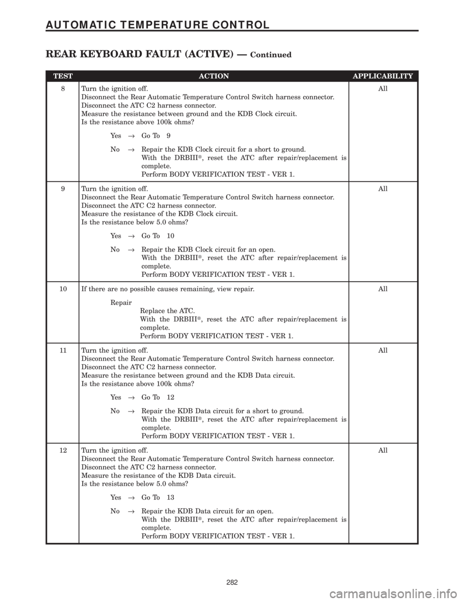
TEST ACTION APPLICABILITY
8 Turn the ignition off.
Disconnect the Rear Automatic Temperature Control Switch harness connector.
Disconnect the ATC C2 harness connector.
Measure the resistance between ground and the KDB Clock circuit.
Is the resistance above 100k ohms?All
Ye s®Go To 9
No®Repair the KDB Clock circuit for a short to ground.
With the DRBIIIt, reset the ATC after repair/replacement is
complete.
Perform BODY VERIFICATION TEST - VER 1.
9 Turn the ignition off.
Disconnect the Rear Automatic Temperature Control Switch harness connector.
Disconnect the ATC C2 harness connector.
Measure the resistance of the KDB Clock circuit.
Is the resistance below 5.0 ohms?All
Ye s®Go To 10
No®Repair the KDB Clock circuit for an open.
With the DRBIIIt, reset the ATC after repair/replacement is
complete.
Perform BODY VERIFICATION TEST - VER 1.
10 If there are no possible causes remaining, view repair. All
Repair
Replace the ATC.
With the DRBIIIt, reset the ATC after repair/replacement is
complete.
Perform BODY VERIFICATION TEST - VER 1.
11 Turn the ignition off.
Disconnect the Rear Automatic Temperature Control Switch harness connector.
Disconnect the ATC C2 harness connector.
Measure the resistance between ground and the KDB Data circuit.
Is the resistance above 100k ohms?All
Ye s®Go To 12
No®Repair the KDB Data circuit for a short to ground.
With the DRBIIIt, reset the ATC after repair/replacement is
complete.
Perform BODY VERIFICATION TEST - VER 1.
12 Turn the ignition off.
Disconnect the Rear Automatic Temperature Control Switch harness connector.
Disconnect the ATC C2 harness connector.
Measure the resistance of the KDB Data circuit.
Is the resistance below 5.0 ohms?All
Ye s®Go To 13
No®Repair the KDB Data circuit for an open.
With the DRBIIIt, reset the ATC after repair/replacement is
complete.
Perform BODY VERIFICATION TEST - VER 1.
282
AUTOMATIC TEMPERATURE CONTROL
REAR KEYBOARD FAULT (ACTIVE) ÐContinued
Page 1041 of 4284
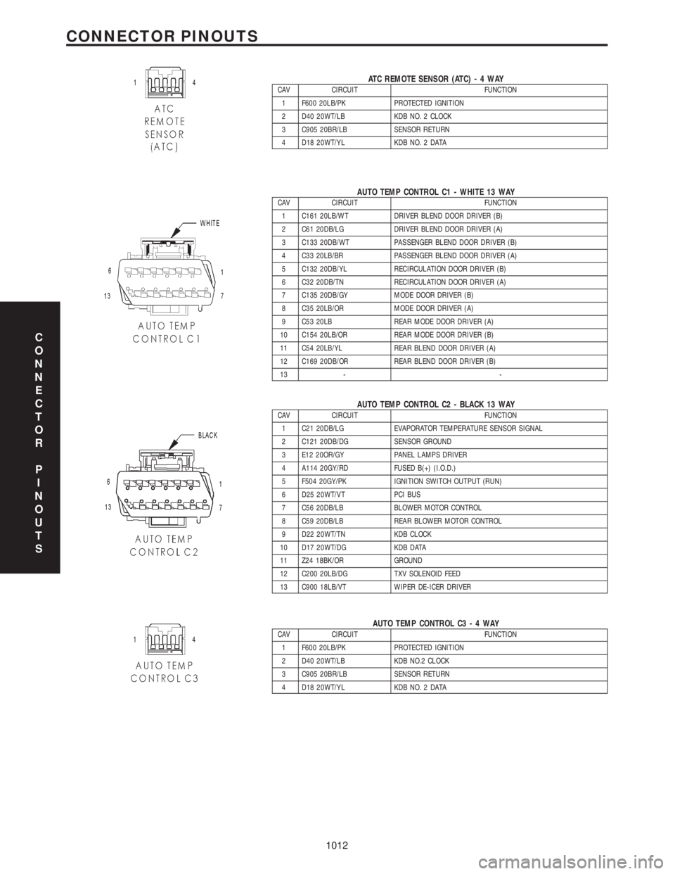
ATC REMOTE SENSOR (ATC)-4WAYCAV CIRCUIT FUNCTION
1 F600 20LB/PK PROTECTED IGNITION
2 D40 20WT/LB KDB NO. 2 CLOCK
3 C905 20BR/LB SENSOR RETURN
4 D18 20WT/YL KDB NO. 2 DATA
AUTO TEMP CONTROL C1 - WHITE 13 WAYCAV CIRCUIT FUNCTION
1 C161 20LB/WT DRIVER BLEND DOOR DRIVER (B)
2 C61 20DB/LG DRIVER BLEND DOOR DRIVER (A)
3 C133 20DB/WT PASSENGER BLEND DOOR DRIVER (B)
4 C33 20LB/BR PASSENGER BLEND DOOR DRIVER (A)
5 C132 20DB/YL RECIRCULATION DOOR DRIVER (B)
6 C32 20DB/TN RECIRCULATION DOOR DRIVER (A)
7 C135 20DB/GY MODE DOOR DRIVER (B)
8 C35 20LB/OR MODE DOOR DRIVER (A)
9 C53 20LB REAR MODE DOOR DRIVER (A)
10 C154 20LB/OR REAR MODE DOOR DRIVER (B)
11 C54 20LB/YL REAR BLEND DOOR DRIVER (A)
12 C169 20DB/OR REAR BLEND DOOR DRIVER (B)
13 - -
AUTO TEMP CONTROL C2 - BLACK 13 WAYCAV CIRCUIT FUNCTION
1 C21 20DB/LG EVAPORATOR TEMPERATURE SENSOR SIGNAL
2 C121 20DB/DG SENSOR GROUND
3 E12 20OR/GY PANEL LAMPS DRIVER
4 A114 20GY/RD FUSED B(+) (I.O.D.)
5 F504 20GY/PK IGNITION SWITCH OUTPUT (RUN)
6 D25 20WT/VT PCI BUS
7 C56 20DB/LB BLOWER MOTOR CONTROL
8 C59 20DB/LB REAR BLOWER MOTOR CONTROL
9 D22 20WT/TN KDB CLOCK
10 D17 20WT/DG KDB DATA
11 Z24 18BK/OR GROUND
12 C200 20LB/DG TXV SOLENOID FEED
13 C900 18LB/VT WIPER DE-ICER DRIVER
AUTO TEMP CONTROL C3-4WAYCAV CIRCUIT FUNCTION
1 F600 20LB/PK PROTECTED IGNITION
2 D40 20WT/LB KDB NO.2 CLOCK
3 C905 20BR/LB SENSOR RETURN
4 D18 20WT/YL KDB NO. 2 DATA
C
O
N
N
E
C
T
O
R
P
I
N
O
U
T
S
1012
CONNECTOR PINOUTS
Page 1062 of 4284
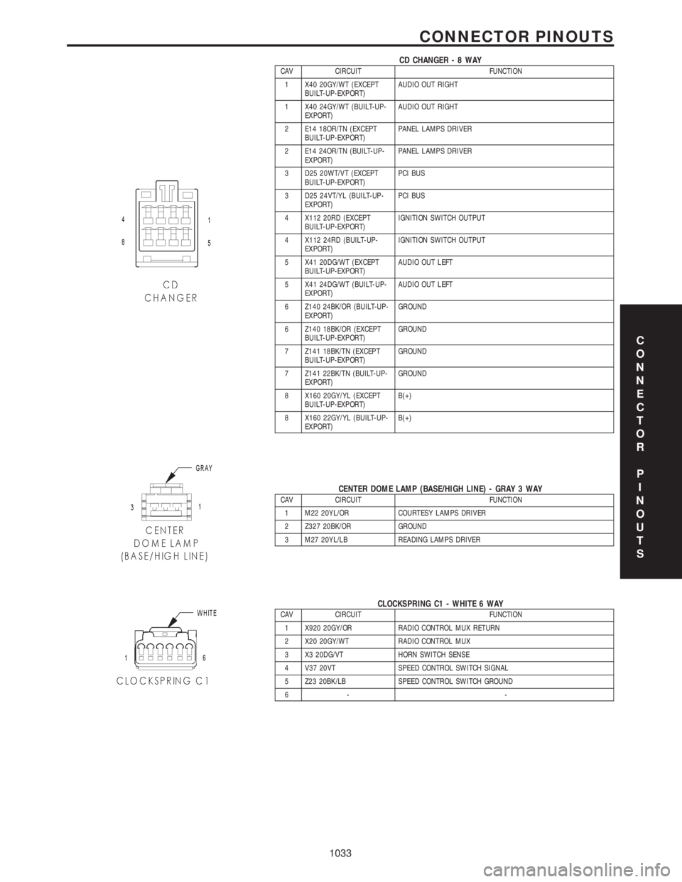
CD CHANGER-8WAYCAV CIRCUIT FUNCTION
1 X40 20GY/WT (EXCEPT
BUILT-UP-EXPORT)AUDIO OUT RIGHT
1 X40 24GY/WT (BUILT-UP-
EXPORT)AUDIO OUT RIGHT
2 E14 18OR/TN (EXCEPT
BUILT-UP-EXPORT)PANEL LAMPS DRIVER
2 E14 24OR/TN (BUILT-UP-
EXPORT)PANEL LAMPS DRIVER
3 D25 20WT/VT (EXCEPT
BUILT-UP-EXPORT)PCI BUS
3 D25 24VT/YL (BUILT-UP-
EXPORT)PCI BUS
4 X112 20RD (EXCEPT
BUILT-UP-EXPORT)IGNITION SWITCH OUTPUT
4 X112 24RD (BUILT-UP-
EXPORT)IGNITION SWITCH OUTPUT
5 X41 20DG/WT (EXCEPT
BUILT-UP-EXPORT)AUDIO OUT LEFT
5 X41 24DG/WT (BUILT-UP-
EXPORT)AUDIO OUT LEFT
6 Z140 24BK/OR (BUILT-UP-
EXPORT)GROUND
6 Z140 18BK/OR (EXCEPT
BUILT-UP-EXPORT)GROUND
7 Z141 18BK/TN (EXCEPT
BUILT-UP-EXPORT)GROUND
7 Z141 22BK/TN (BUILT-UP-
EXPORT)GROUND
8 X160 20GY/YL (EXCEPT
BUILT-UP-EXPORT)B(+)
8 X160 22GY/YL (BUILT-UP-
EXPORT)B(+)
CENTER DOME LAMP (BASE/HIGH LINE) - GRAY 3 WAYCAV CIRCUIT FUNCTION
1 M22 20YL/OR COURTESY LAMPS DRIVER
2 Z327 20BK/OR GROUND
3 M27 20YL/LB READING LAMPS DRIVER
CLOCKSPRING C1 - WHITE 6 WAYCAV CIRCUIT FUNCTION
1 X920 20GY/OR RADIO CONTROL MUX RETURN
2 X20 20GY/WT RADIO CONTROL MUX
3 X3 20DG/VT HORN SWITCH SENSE
4 V37 20VT SPEED CONTROL SWITCH SIGNAL
5 Z23 20BK/LB SPEED CONTROL SWITCH GROUND
6- -
C
O
N
N
E
C
T
O
R
P
I
N
O
U
T
S
1033
CONNECTOR PINOUTS
Page 1063 of 4284
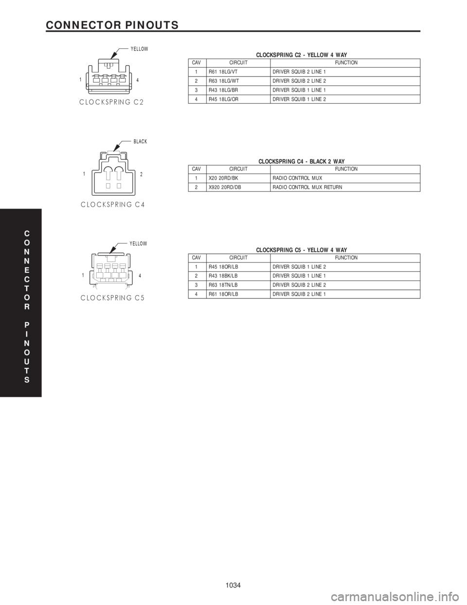
CLOCKSPRING C2 - YELLOW 4 WAYCAV CIRCUIT FUNCTION
1 R61 18LG/VT DRIVER SQUIB 2 LINE 1
2 R63 18LG/WT DRIVER SQUIB 2 LINE 2
3 R43 18LG/BR DRIVER SQUIB 1 LINE 1
4 R45 18LG/OR DRIVER SQUIB 1 LINE 2
CLOCKSPRING C4 - BLACK 2 WAYCAV CIRCUIT FUNCTION
1 X20 20RD/BK RADIO CONTROL MUX
2 X920 20RD/DB RADIO CONTROL MUX RETURN
CLOCKSPRING C5 - YELLOW 4 WAYCAV CIRCUIT FUNCTION
1 R45 18OR/LB DRIVER SQUIB 1 LINE 2
2 R43 18BK/LB DRIVER SQUIB 1 LINE 1
3 R63 18TN/LB DRIVER SQUIB 2 LINE 2
4 R61 18OR/LB DRIVER SQUIB 2 LINE 1
C
O
N
N
E
C
T
O
R
P
I
N
O
U
T
S
1034
CONNECTOR PINOUTS
Page 1104 of 4284
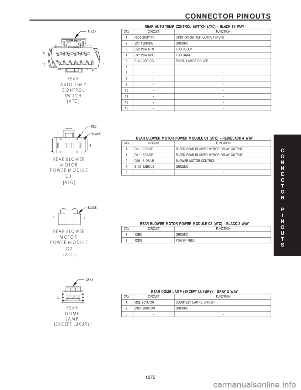
REAR AUTO TEMP CONTROL SWITCH (ATC) - BLACK 13 WAYCAV CIRCUIT FUNCTION
1 F504 20GY/PK IGNITION SWITCH OUTPUT (RUN)
2 Z27 18BK/DG GROUND
3 D22 20WT/TN KDB CLOCK
4 D17 20WT/DG KDB DATA
5 E10 20OR/DG PANEL LAMPS DRIVER
6- -
7- -
8- -
9- -
10 - -
11 - -
12 - -
13 - -
REAR BLOWER MOTOR POWER MODULE C1 (ATC) - RED/BLACK 4 WAYCAV CIRCUIT FUNCTION
1 C51 12DB/BR FUSED REAR BLOWER MOTOR RELAY OUTPUT
1 C51 18DB/BR FUSED REAR BLOWER MOTOR RELAY OUTPUT
2 C59 18 DB/LB BLOWER MOTOR CONTROL
3 Z135 12BK/LB GROUND
4- -
REAR BLOWER MOTOR POWER MODULE C2 (ATC) - BLACK 2 WAYCAV CIRCUIT FUNCTION
1 12BK GROUND
2 12DG POWER FEED
REAR DOME LAMP (EXCEPT LUXURY) - GRAY 3 WAYCAV CIRCUIT FUNCTION
1 M22 20YL/OR COURTESY LAMPS DRIVER
2 Z327 20BK/OR GROUND
3- -
C
O
N
N
E
C
T
O
R
P
I
N
O
U
T
S
1075
CONNECTOR PINOUTS
Page 1539 of 4284
ASSEMBLY - STRUT ASSEMBLY
For the disassembly and assembly of the strut
assembly, use of Strut Spring Compressor, Pentastar
Service Equipment (PSE) tool W-7200, or the equiva-
lent, is recommended to compress the coil spring.
Follow the manufacturer's instructions closely.
NOTE: Coil Springs on this vehicle are side-ori-
ented. Springs on the left side of the vehicle have a
left-hand wind top-to-bottom while springs on the
right side have a right-hand wind top-to-bottom.
Left and right springs must not be interchanged.
NOTE: If the coil spring has been removed from the
spring compressor, proceed with the next step, oth-
erwise, proceed with step 5.
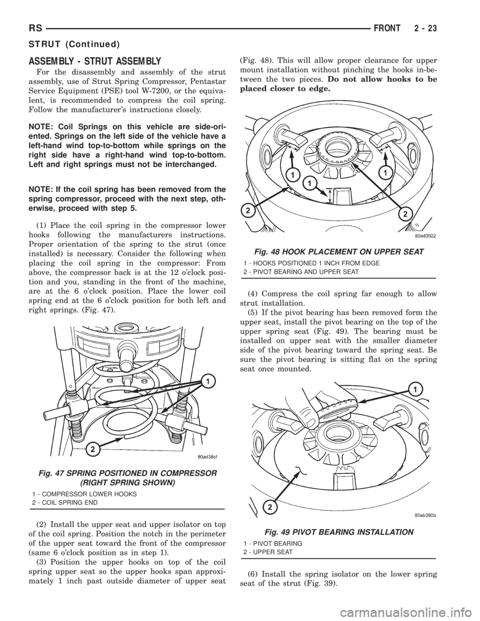
(1) Place the coil spring in the compressor lower
hooks following the manufacturers instructions.
Proper orientation of the spring to the strut (once
installed) is necessary. Consider the following when
placing the coil spring in the compressor: From
above, the compressor back is at the 12 o'clock posi-
tion and you, standing in the front of the machine,
are at the 6 o'clock position. Place the lower coil
spring end at the 6 o'clock position for both left and
right springs. (Fig. 47).
(2) Install the upper seat and upper isolator on top
of the coil spring. Position the notch in the perimeter
of the upper seat toward the front of the compressor
(same 6 o'clock position as in step 1).
(3) Position the upper hooks on top of the coil
spring upper seat so the upper hooks span approxi-
mately 1 inch past outside diameter of upper seat(Fig. 48). This will allow proper clearance for upper
mount installation without pinching the hooks in-be-
tween the two pieces.Do not allow hooks to be
placed closer to edge.
(4) Compress the coil spring far enough to allow
strut installation.
(5) If the pivot bearing has been removed form the
upper seat, install the pivot bearing on the top of the
upper spring seat (Fig. 49). The bearing must be
installed on upper seat with the smaller diameter
side of the pivot bearing toward the spring seat. Be
sure the pivot bearing is sitting flat on the spring
seat once mounted.
(6) Install the spring isolator on the lower spring
seat of the strut (Fig. 39).
Fig. 47 SPRING POSITIONED IN COMPRESSOR
(RIGHT SPRING SHOWN)
1 - COMPRESSOR LOWER HOOKS
2 - COIL SPRING END
Fig. 48 HOOK PLACEMENT ON UPPER SEAT
1 - HOOKS POSITIONED 1 INCH FROM EDGE
2 - PIVOT BEARING AND UPPER SEAT
Fig. 49 PIVOT BEARING INSTALLATION
1 - PIVOT BEARING
2 - UPPER SEAT
RSFRONT2-23
STRUT (Continued)
Page 1540 of 4284
(7) Install the jounce bumper on the strut shaft
(Fig. 39). The jounce bumper is to be installed with
the small end pointing downward.
(8) Install the dust shield on the strut. Collapse
and stretch the dust shield down over the top of the
jounce bumper until the dust shield snaps into the
slot on the jounce bumper. The jounce bumper will be
at the top of the inner dust boot. Return the dust
shield to its fully extended length.
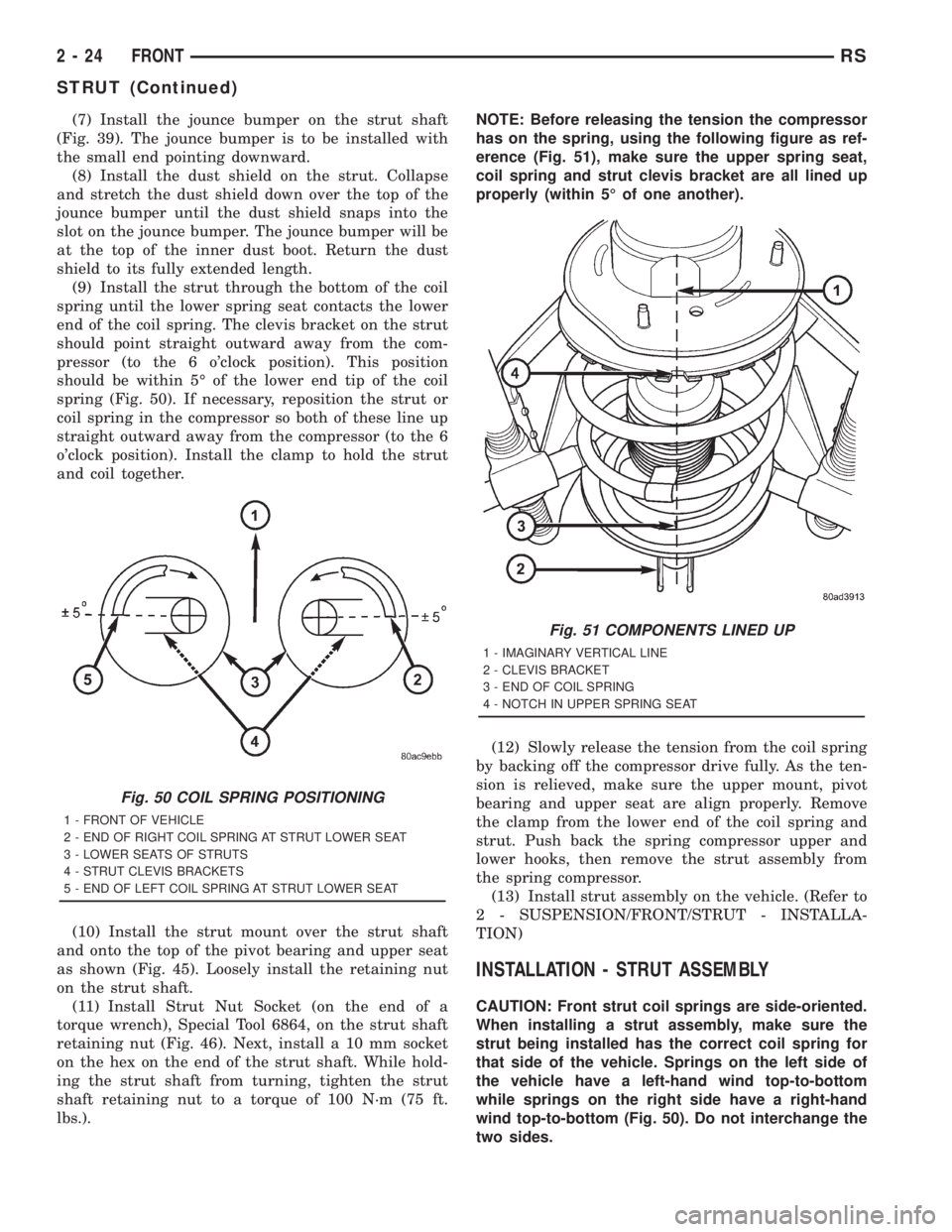
(9) Install the strut through the bottom of the coil
spring until the lower spring seat contacts the lower
end of the coil spring. The clevis bracket on the strut
should point straight outward away from the com-
pressor (to the 6 o'clock position). This position
should be within 5É of the lower end tip of the coil
spring (Fig. 50). If necessary, reposition the strut or
coil spring in the compressor so both of these line up
straight outward away from the compressor (to the 6
o'clock position). Install the clamp to hold the strut
and coil together.
(10) Install the strut mount over the strut shaft
and onto the top of the pivot bearing and upper seat
as shown (Fig. 45). Loosely install the retaining nut
on the strut shaft.
(11) Install Strut Nut Socket (on the end of a
torque wrench), Special Tool 6864, on the strut shaft
retaining nut (Fig. 46). Next, install a 10 mm socket
on the hex on the end of the strut shaft. While hold-
ing the strut shaft from turning, tighten the strut
shaft retaining nut to a torque of 100 N´m (75 ft.
lbs.).NOTE: Before releasing the tension the compressor
has on the spring, using the following figure as ref-
erence (Fig. 51), make sure the upper spring seat,
coil spring and strut clevis bracket are all lined up
properly (within 5É of one another).
(12) Slowly release the tension from the coil spring
by backing off the compressor drive fully. As the ten-
sion is relieved, make sure the upper mount, pivot
bearing and upper seat are align properly. Remove
the clamp from the lower end of the coil spring and
strut. Push back the spring compressor upper and
lower hooks, then remove the strut assembly from
the spring compressor.
(13) Install strut assembly on the vehicle. (Refer to
2 - SUSPENSION/FRONT/STRUT - INSTALLA-
TION)
INSTALLATION - STRUT ASSEMBLY
CAUTION: Front strut coil springs are side-oriented.
When installing a strut assembly, make sure the
strut being installed has the correct coil spring for
that side of the vehicle. Springs on the left side of
the vehicle have a left-hand wind top-to-bottom
while springs on the right side have a right-hand
wind top-to-bottom (Fig. 50). Do not interchange the
two sides.
Fig. 50 COIL SPRING POSITIONING
1 - FRONT OF VEHICLE
2 - END OF RIGHT COIL SPRING AT STRUT LOWER SEAT
3 - LOWER SEATS OF STRUTS
4 - STRUT CLEVIS BRACKETS
5 - END OF LEFT COIL SPRING AT STRUT LOWER SEAT
Fig. 51 COMPONENTS LINED UP
1 - IMAGINARY VERTICAL LINE
2 - CLEVIS BRACKET
3 - END OF COIL SPRING
4 - NOTCH IN UPPER SPRING SEAT
2 - 24 FRONTRS
STRUT (Continued)
Page 1551 of 4284
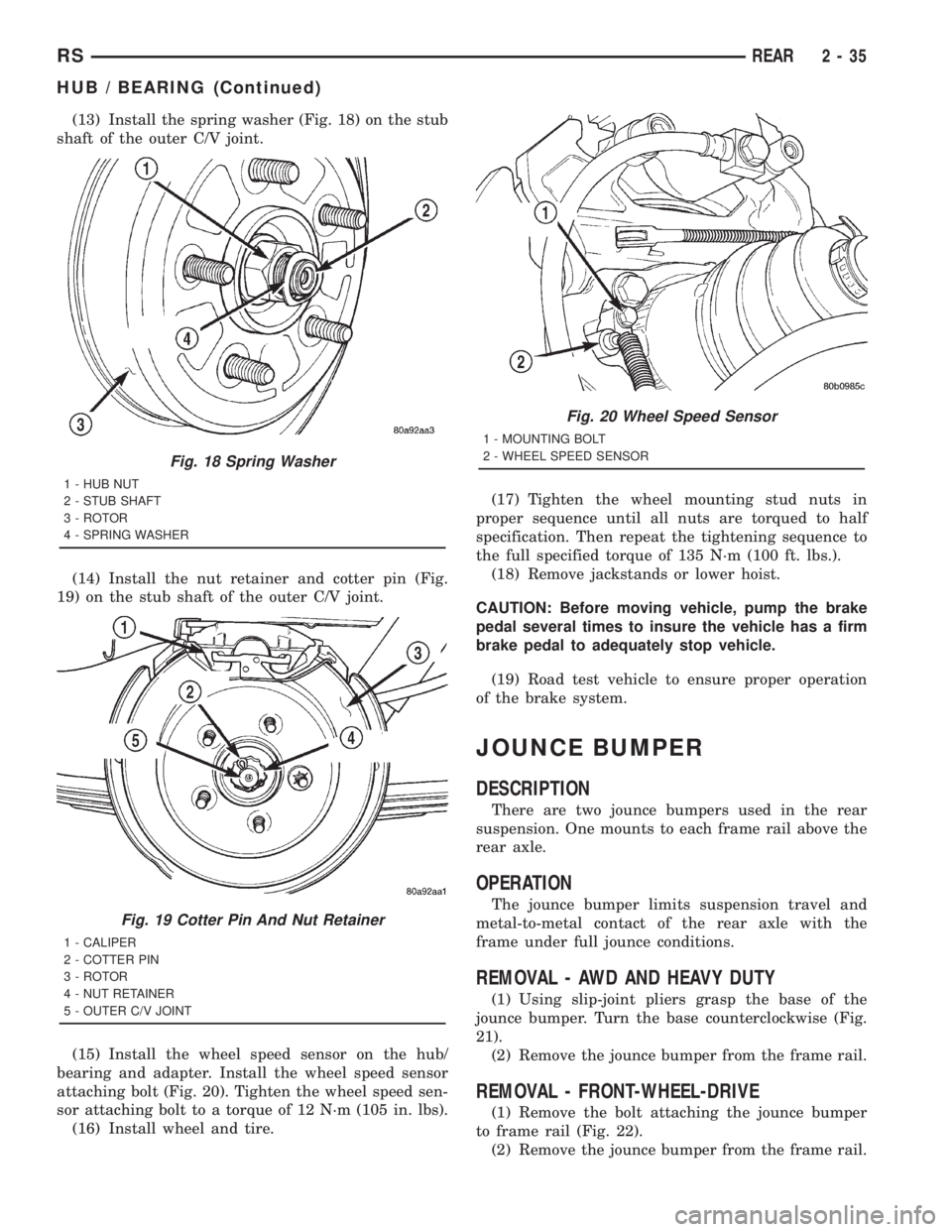
(13) Install the spring washer (Fig. 18) on the stub
shaft of the outer C/V joint.
(14) Install the nut retainer and cotter pin (Fig.
19) on the stub shaft of the outer C/V joint.
(15) Install the wheel speed sensor on the hub/
bearing and adapter. Install the wheel speed sensor
attaching bolt (Fig. 20). Tighten the wheel speed sen-
sor attaching bolt to a torque of 12 N´m (105 in. lbs).
(16) Install wheel and tire.(17) Tighten the wheel mounting stud nuts in
proper sequence until all nuts are torqued to half
specification. Then repeat the tightening sequence to
the full specified torque of 135 N´m (100 ft. lbs.).
(18) Remove jackstands or lower hoist.
CAUTION: Before moving vehicle, pump the brake
pedal several times to insure the vehicle has a firm
brake pedal to adequately stop vehicle.
(19) Road test vehicle to ensure proper operation
of the brake system.
JOUNCE BUMPER
DESCRIPTION
There are two jounce bumpers used in the rear
suspension. One mounts to each frame rail above the
rear axle.
OPERATION
The jounce bumper limits suspension travel and
metal-to-metal contact of the rear axle with the
frame under full jounce conditions.
REMOVAL - AWD AND HEAVY DUTY
(1) Using slip-joint pliers grasp the base of the
jounce bumper. Turn the base counterclockwise (Fig.
21).
(2) Remove the jounce bumper from the frame rail.
REMOVAL - FRONT-WHEEL-DRIVE
(1) Remove the bolt attaching the jounce bumper
to frame rail (Fig. 22).
(2) Remove the jounce bumper from the frame rail.
Fig. 18 Spring Washer
1 - HUB NUT
2 - STUB SHAFT
3 - ROTOR
4 - SPRING WASHER
Fig. 19 Cotter Pin And Nut Retainer
1 - CALIPER
2 - COTTER PIN
3 - ROTOR
4 - NUT RETAINER
5 - OUTER C/V JOINT
Fig. 20 Wheel Speed Sensor
1 - MOUNTING BOLT
2 - WHEEL SPEED SENSOR
RSREAR2-35
HUB / BEARING (Continued)
Page 1608 of 4284
ASSEMBLY
(1) Install output flange seals using tools C4171
and 8493 (Fig. 15).
(2) Install large overrunning clutch housing o-ring
to differential assembly (Fig. 14).
(3) Install shim to differential pinion shaft (Fig.
16).
(4) Install viscous coupler to differential pinion
shaft (Fig. 17).
(5) Install overrunning clutch assembly to viscous
coupler (Fig. 18).
(6) Install washer to overrunning clutch (Fig. 14).
(7) Install o-ring to overrunning clutch (Fig. 14).
(8) Align overrunning clutch ground tab to 12
o'clock position (Fig. 19).
(9) Install overrunning clutch housing into posi-
tion, making sure ground tab engages with notch in
housing (Fig. 20).
(10) Install and torque overrunning clutch hous-
ing-to-differential assembly bolts (Fig. 21) to 60 N´m
(44 ft. lbs.).
(11) Install input flange seal using tool 8802 (Fig.
22).
(12) Install flange/shield assembly (Fig. 23).
(13) Install input flange washer and nut. Using
tool 6958 (Fig. 24), torque nut to 135 N´m (100 ft.
lbs.).
(14) Install torque arm assembly into position.
Install and torque torque arm-to-differential assem-
bly bolts (Fig. 25) to 60 N´m (44 ft. lbs.).
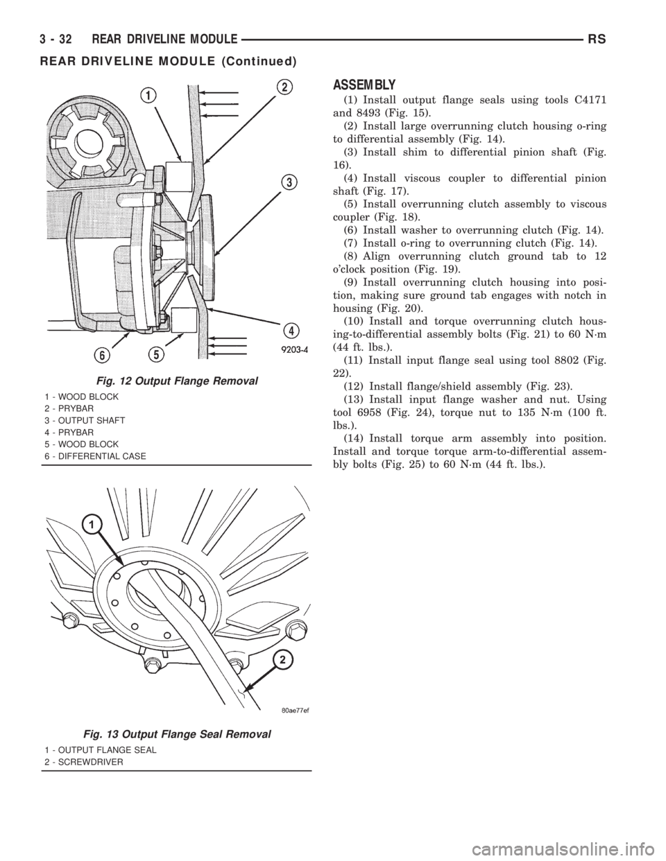
Fig. 12 Output Flange Removal
1 - WOOD BLOCK
2 - PRYBAR
3 - OUTPUT SHAFT
4 - PRYBAR
5 - WOOD BLOCK
6 - DIFFERENTIAL CASE
Fig. 13 Output Flange Seal Removal
1 - OUTPUT FLANGE SEAL
2 - SCREWDRIVER
3 - 32 REAR DRIVELINE MODULERS
REAR DRIVELINE MODULE (Continued)
Page 1610 of 4284
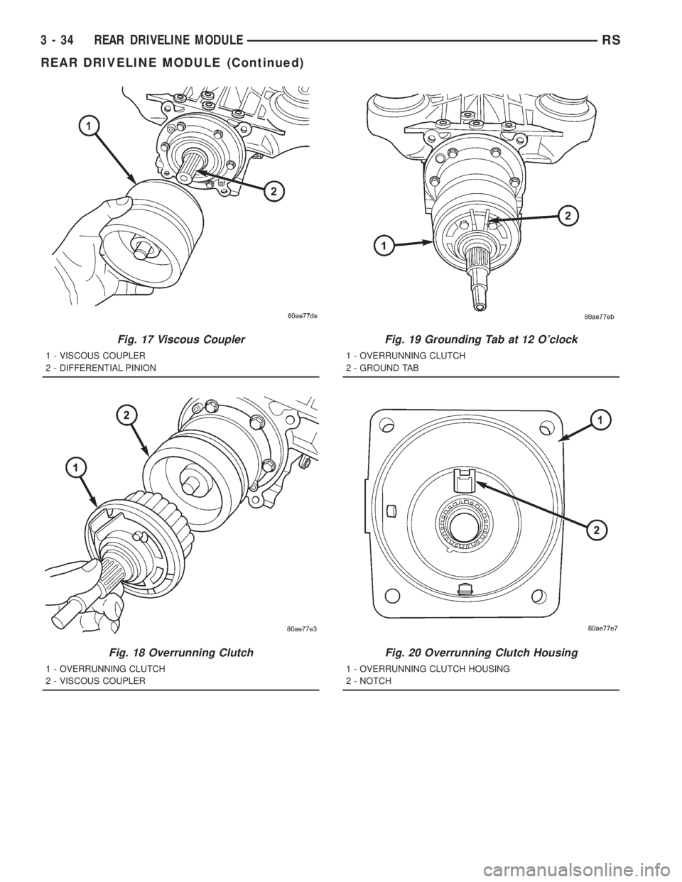
Fig. 17 Viscous Coupler
1 - VISCOUS COUPLER
2 - DIFFERENTIAL PINION
Fig. 18 Overrunning Clutch
1 - OVERRUNNING CLUTCH
2 - VISCOUS COUPLER
Fig. 19 Grounding Tab at 12 O'clock
1 - OVERRUNNING CLUTCH
2 - GROUND TAB
Fig. 20 Overrunning Clutch Housing
1 - OVERRUNNING CLUTCH HOUSING
2 - NOTCH
3 - 34 REAR DRIVELINE MODULERS
REAR DRIVELINE MODULE (Continued)