sensor CHRYSLER VOYAGER 2001 Service Manual
[x] Cancel search | Manufacturer: CHRYSLER, Model Year: 2001, Model line: VOYAGER, Model: CHRYSLER VOYAGER 2001Pages: 4284, PDF Size: 83.53 MB
Page 2682 of 4284

(9) Connect vacuum lines for power brake booster,
LDP, EGR transducer, and speed control vacuum res-
ervoir (if equipped) at upper intake manifold fittings.
(10) Connect vacuum lines for purge solenoid and
PCV valve.
(11) Connect electrical connectors for MAP sensor,
throttle position sensor (TPS), and idle air control
(IAC) motor.
(12) Install air cleaner upper housing and air
intake tube to throttle body.
(13) Connect inlet air temperature sensor connec-
tor (Fig. 104).
(14) Connect negative cable to battery.
INTAKE MANIFOLD - LOWER
REMOVAL
(1) Perform fuel system pressure release proce-
durebefore attempting any repairs.(Refer to 14 -
FUEL SYSTEM/FUEL DELIVERY - STANDARD
PROCEDURE)
(2) Remove upper intake manifold. (Refer to 9 -
ENGINE/MANIFOLDS/INTAKE MANIFOLD -
REMOVAL)
CAUTION: Cover intake manifold openings to pre-
vent foreign material from entering engine.
(3) Disconnect fuel line. (Refer to 14 - FUEL SYS-
TEM/FUEL DELIVERY/QUICK CONNECT FIT-
TING - STANDARD PROCEDURE)
(4) Drain the cooling system. (Refer to 7 - COOL-
ING - STANDARD PROCEDURE)
(5) Remove heater supply and radiator upper
hoses at intake manifold.
(6) Disconnect coolant temperature sensor/fuel
injector wire harness connector.
(7) Remove lower intake manifold support bracket
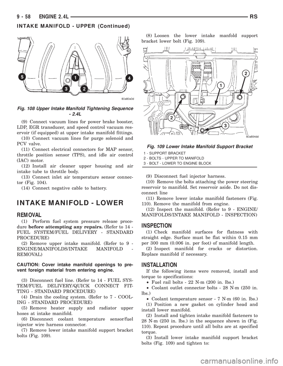
bolts (Fig. 109).(8) Loosen the lower intake manfold support
bracket lower bolt (Fig. 109).
(9) Disconnect fuel injector harness.
(10) Remove the bolts attaching the power steering
reservoir to manifold. Set reservoir aside. Do not dis-
connect line
(11) Remove lower intake manifold fasteners (Fig.
110). Remove the manifold from engine.
(12) Inspect the manifold. (Refer to 9 - ENGINE/
MANIFOLDS/INTAKE MANIFOLD - INSPECTION)
INSPECTION
(1) Check manifold surfaces for flatness with
straight edge. Surface must be flat within 0.15 mm
per 300 mm (0.006 in. per foot) of manifold length.
(2) Inspect manifold for cracks or distortion.
Replace manifold if necessary.
INSTALLATION
If the following items were removed, install and
torque to specifications:
²Fuel rail bolts - 22 N´m (200 in. lbs.)
²Coolant outlet connector bolts - 28 N´m (250 in.
lbs.)
²Coolant temperature sensor - 7 N´m (60 in. lbs.)
(1) Position a new gasket on cylinder head and
install lower manifold.
(2) Install and tighten intake manifold fasteners to
28 N´m (250 in. lbs.) in the sequence shown in (Fig.
110). Repeat procedure until all bolts are at specified
torque.
(3) Install lower intake manifold support bracket
bolts (Fig. 109) and tighten to:
Fig. 108 Upper Intake Manifold Tightening Sequence
- 2.4L
Fig. 109 Lower Intake Manifold Support Bracket
1 - SUPPORT BRACKET
2 - BOLTS - UPPER TO MANIFOLD
3 - BOLT - LOWER TO ENGINE BLOCK
9 - 58 ENGINE 2.4LRS
INTAKE MANIFOLD - UPPER (Continued)
Page 2683 of 4284

²Bolts to intake 28 N´m (250 in. lbs.)
²Bolt to engine block 54 N´m (40 ft. lbs.)
(4) Position power steering reservoir on manifold
and install bolts.
(5) Connect the fuel line. (Refer to 14 - FUEL SYS-
TEM/FUEL DELIVERY/QUICK CONNECT FIT-
TING - STANDARD PROCEDURE)
(6) Connect coolant temperature sensor/fuel injec-
tor wiring harness electrical connector.
(7) Install the radiator upper and heater supply
hoses.
(8) Install the upper intake manifold. (Refer to 9 -
ENGINE/MANIFOLDS/INTAKE MANIFOLD -
INSTALLATION)
(9) Fill the cooling system. (Refer to 7 - COOLING
- STANDARD PROCEDURE)
EXHAUST MANIFOLD
DESCRIPTION
The exhaust manifold is made of Hi-Silicone Moly
nodular cast iron for strength and high tempera-
tures. The manifold attaches to the cylinder head.
OPERATION
The exhaust manifold collects the exhaust gasses
exiting the combustion chambers. Then it channels
the exhaust gasses to the exhaust pipe attached to
the manifold.
REMOVAL
(1) Raise vehicle and disconnect exhaust pipe from
the exhaust manifold.
(2) Disconnect upstream oxygen sensor connector
at the rear of exhaust manifold.
(3) Remove the bolts attaching the manifold to the
cylinder head.
(4) Remove exhaust manifold.
(5) Inspect the manifold. (Refer to 9 - ENGINE/
MANIFOLDS/EXHAUST MANIFOLD - INSPEC-
TION)
CLEANING
(1) Discard gasket (if equipped) and clean all sur-
faces of manifold and cylinder head.
INSPECTION
(1) Inspect manifold gasket surfaces for flatness
with straight edge. Surface must be flat within 0.15
mm per 300 mm (0.006 in. per foot) of manifold
length.
(2) Inspect manifolds for cracks or distortion.
Replace manifold as necessary.
INSTALLATION
(1) Install exhaust manifold with a new gasket.
Tighten attaching nuts in the sequence shown in
(Fig. 111) to 20 N´m (175 in. lbs.).
(2) Attach exhaust pipe to exhaust manifold and
tighten fasteners to 37 N´m (27 ft. lbs.).
(3) Install and connect the oxygen sensor. (Refer to
14 - FUEL SYSTEM/FUEL INJECTION/O2 SENSOR
- COMPONENT LOCATION)
Fig. 110 Lower Intake Manifold Tightening Sequence
Fig. 111 Exhaust Manifold Tightening Sequence
RSENGINE 2.4L9-59
INTAKE MANIFOLD - LOWER (Continued)
Page 2696 of 4284

REMOVAL.............................114
INSTALLATION..........................115
CRANKSHAFT OIL SEAL - FRONT
REMOVAL.............................115
INSTALLATION..........................115
CRANKSHAFT OIL SEAL - REAR
REMOVAL.............................116
INSTALLATION..........................117
CRANKSHAFT REAR OIL SEAL RETAINER
REMOVAL.............................117
INSTALLATION..........................117
FLEX PLATE
REMOVAL.............................118
INSTALLATION..........................118
HYDRAULIC LIFTERS (CAM IN BLOCK)
DESCRIPTION..........................118
DIAGNOSIS AND TESTING................118
HYDRAULIC LIFTERS...................118
REMOVAL.............................119
INSTALLATION..........................119
PISTON & CONNECTING ROD
DESCRIPTION..........................119
OPERATION............................120
STANDARD PROCEDURE.................120
CONNECTING ROD AND BEARING -
FITTING.............................120
PISTON - FITTING.....................121
REMOVAL.............................121
INSTALLATION..........................122
PISTON RINGS
STANDARD PROCEDURE.................124
PISTON RING - FITTING................124
REMOVAL.............................124
INSTALLATION..........................125
VIBRATION DAMPER
REMOVAL.............................126
INSTALLATION..........................126
ENGINE MOUNTING
DESCRIPTION..........................127
FRONT MOUNT
REMOVAL.............................127
INSTALLATION..........................127
LEFT MOUNT
REMOVAL.............................128
INSTALLATION..........................128
REAR MOUNT
REMOVAL.............................129
INSTALLATION..........................130
RIGHT MOUNT
REMOVAL.............................130
INSTALLATION..........................131
LUBRICATION
DESCRIPTION..........................131
OPERATION............................131
DIAGNOSIS AND TESTING................131
ENGINE OIL PRESSURE................131OIL
STANDARD PROCEDURE.................132
ENGINE OIL CHANGE..................132
ENGINE OIL LEVEL CHECK..............133
OIL COOLER & LINES
DESCRIPTION..........................134
OPERATION............................134
REMOVAL.............................134
INSTALLATION..........................134
OIL FILTER
REMOVAL.............................135
INSTALLATION..........................135
OIL FILTER ADAPTER
REMOVAL.............................135
INSTALLATION..........................135
OIL PAN
REMOVAL.............................136
CLEANING.............................136
INSPECTION...........................136
INSTALLATION..........................136
OIL PRESSURE RELIEF VALVE
REMOVAL.............................137
INSTALLATION..........................137
OIL PRESSURE SENSOR/SWITCH
DESCRIPTION..........................137
OPERATION............................138
REMOVAL.............................138
INSTALLATION..........................138
OIL PUMP
DESCRIPTION..........................138
REMOVAL.............................138
DISASSEMBLY..........................138
CLEANING.............................138
INSPECTION...........................138
ASSEMBLY............................140
INSTALLATION..........................140
INTAKE MANIFOLD
DESCRIPTION..........................140
OPERATION............................141
DIAGNOSIS AND TESTING................141
INTAKE MANIFOLD LEAKS..............141
INTAKE MANIFOLD - UPPER 3.3L
STANDARD PROCEDURE.................141
MANIFOLD STRIPPED THREAD REPAIR....141
INTAKE MANIFOLD VACUUM PORT REPAIR . 142
REMOVAL.............................143
CLEANING.............................144
INSPECTION...........................144
INSTALLATION..........................144
INTAKE MANIFOLD - UPPER 3.8L
REMOVAL.............................145
CLEANING.............................146
INSPECTION...........................147
INSTALLATION..........................147
INTAKE MANIFOLD - LOWER
REMOVAL.............................148
CLEANING.............................148
9 - 72 ENGINE 3.3/3.8LRS
Page 2706 of 4284

REMOVAL - ENGINE ASSEMBLY
(1) Perform fuel pressure release procedure. (Refer
to 14 - FUEL SYSTEM/FUEL DELIVERY - STAN-
DARD PROCEDURE)
(2) Disconnect the battery.
(3) Remove air cleaner and hoses.
(4) Disconnect the fuel line from fuel rail. (Refer to
14 - FUEL SYSTEM/FUEL DELIVERY/QUICK
CONNECT FITTING - STANDARD PROCEDURE)
(5) Remove the wiper module. (Refer to 8 - ELEC-
TRICAL/WIPERS/WASHERS/WIPER MODULE -
REMOVAL)
(6) Block off heater hoses to the rear heater sys-
tem, if equipped, using pinch-off pliers.
(7) Drain the cooling system. (Refer to 7 - COOL-
ING - STANDARD PROCEDURE)
(8) Disconnect the heater hoses.
(9) Remove the radiator upper support crossmem-
ber. (Refer to 23 - BODY/EXTERIOR/GRILLE OPEN-
ING REINFORCEMENT - REMOVAL)
(10) Remove the radiator fans. (Refer to 7 - COOL-
ING/ENGINE/RADIATOR FAN - REMOVAL)
(11) Disconnect the throttle cables from the throt-
tle body.
(12) Disconnect the MAP, IAC, and TPS electrical
connectors.
(13) Disconnect the EGR transducer electrical con-
nector.
(14) Disconnect the vacuum hoses from throttle
body.
(15) Disconnect the brake booster and speed con-
trol vacuum hoses.(16) Disengage wire harness clip from the right
side engine mount.
(17) Remove the power steering reservoir from
mounting position and set aside. Do not disconnect
hose.
(18) Disconnect ground strap from rear of cylinder
head.
(19) Disconnect engine coolant temperature (ECT)
sensor and ignition coil electrical connectors.
(20) Disconnect the fuel injector electrical harness
connector and disengage clip from support bracket.
(21) Disconnect crank sensor connector.
(22) Disconnect camshaft sensor connector.
(23) Evacuate air conditioning system.
(24) Disconnect A/C compressor electrical connec-
tor.
(25) Disconnect the A/C lines from compressor.
Cover and seal all openings of hoses and compressor.
(26) Remove the radiator upper hose.
(27) Disengage electrical harness clip at transaxle
dipstick tube.
(28) Remove transaxle dipstick tube. Seal opening
using a suitable plug.
(29) Disconnect cooler hoses from transaxle.
(30) Disconnect transaxle shift linkage and electri-
cal connectors.
(31) Raise vehicle on hoist and drain the engine
oil.
(32) Remove the axle shafts. (Refer to 3 - DIFFER-
ENTIAL & DRIVELINE/HALF SHAFT - REMOVAL)
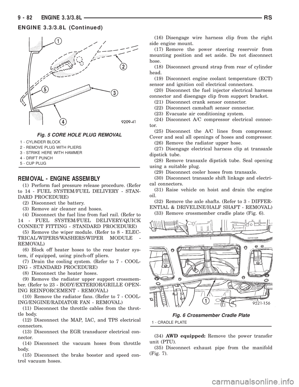
(33) Remove crossmember cradle plate (Fig. 6).
(34)AWD equipped:Remove the power transfer
unit (PTU).
(35) Disconnect exhaust pipe from the manifold
(Fig. 7).
Fig. 5 CORE HOLE PLUG REMOVAL
1 - CYLINDER BLOCK
2 - REMOVE PLUG WITH PLIERS
3 - STRIKE HERE WITH HAMMER
4 - DRIFT PUNCH
5 - CUP PLUG
Fig. 6 Crossmember Cradle Plate
1 - CRADLE PLATE
9 - 82 ENGINE 3.3/3.8LRS
ENGINE 3.3/3.8L (Continued)
Page 2707 of 4284

(36) Remove front engine mount and bracket as an
assembly.
(37) Remove the engine rear mount bracket.
(38) Remove the engine to transaxle struts (Fig. 8).
(39) Remove transaxle case cover (Fig. 8).
(40) Remove flex plate to torque converter bolts.
(41) Remove the power steering pressure hose sup-
port clip attaching bolt.
(42) Disconnect the knock sensor electrical connec-
tor (3.8L only).
(43) Disconnect the engine block heater electrical
connector, if equipped.
(44) Remove the accessory belt splash shield.
(45) Remove accessory drive belt. (Refer to 7 -
COOLING/ACCESSORY DRIVE/DRIVE BELTS -
REMOVAL)
(46) Disconnect the radiator lower hose.
(47) Remove air conditioning compressor from
engine.
(48) Remove the generator. (Refer to 8 - ELECTRI-
CAL/CHARGING/GENERATOR - REMOVAL)
(49) Remove the water pump pulley attaching
bolts and position pulley between pump hub and
housing.
(50) Disconnect the oil pressure switch electrical
connector.
(51) Disconnect wiring harness support clip from
dipstick tube.(52) Install Special Tools 6912 and 8444 Adapters
on the right side (rear) of engine block (Fig. 9).
Fig. 7 Catalytic Converter to Exhaust Manifold
1 - FLAG NUT
2 - GASKET
3 - BOLT
4 - CATALYTIC CONVERTER
Fig. 8 POWERTRAIN SUPPORTS AND DUST COVER
1 - BRACKET - ENGINE REAR MOUNT
2 - BOLT - TRANSAXLE CASE COVER
3 - STRUT - TRANSAXLE TO ENGINE HORIZONTAL
4 - BOLT - HORIZONTAL STRUT
5 - BOLT - STRUT TO TRANSAXLE
6 - COVER - TRANSAXLE CASE LOWER
7 - STRUT - TRANSAXLE TO ENGINE
8 - BOLT - STRUT TO ENGINE
9 - BOLT - ENGINE REAR MOUNT BRACKET
Fig. 9 ADAPTER TOOLS MOUNTED ON BLOCK
1 - SPECIAL TOOL 6912
2 - SPECIAL TOOL 8444
RSENGINE 3.3/3.8L9-83
ENGINE 3.3/3.8L (Continued)
Page 2709 of 4284

(4) Slowly raise vehicle enough to remove the
engine dolly and cradle Special Tools 6135, 6710,
6848 and 6909 (Fig. 10).
(5) Remove Special Tools 6912 and 8444.
(6) Lower the vehicle.
(7) Install power steering pump and pressure line
support.(8) Install the generator and wiring harness.
(Refer to 8 - ELECTRICAL/CHARGING/GENERA-
TOR - INSTALLATION)
(9) Raise vehicle.
(10) Attach wiring harness support clip to the dip-
stick tube.
(11) Connect oil pressure switch electrical connec-
tor.
(12) Install the A/C compressor.
(13) Install the water pump pulley.
(14) Connect the radiator lower hose.
(15) Install the accessory drive belt and splash
shield. (Refer to 7 - COOLING/ACCESSORY DRIVE/
DRIVE BELTS - INSTALLATION)
(16) Connect the engine block heater electrical con-
nector, if equipped.
(17) Connect the knock sensor electrical connector
(3.8L only).
(18) Install the torque converter to flex plate bolts.
(19) Install the transaxle case cover (Fig. 8).
(20) Install the powertrain struts (Fig. 8).
(21) Install the engine rear mount bracket.
(22) Install the engine front mount and bracket
assembly.
(23)AWD equipped;Install the power transfer
unit (PTU).
(24) Install the axle shafts. (Refer to 3 - DIFFER-
ENTIAL & DRIVELINE/HALF SHAFT - INSTALLA-
TION)
(25) Connect exhaust pipe to manifold (Fig. 7).
(26) Install crossmember cradle plate (Fig. 6).
(27) Lower vehicle.
(28) Connect transaxle shift linkage.
(29) Connect transaxle electrical connectors.
(30) Connect transaxle cooler hoses.
(31) Install transaxle dipstick tube and attach
electrical harness clip.
(32) Connect the radiator upper hose.
(33) Connect the A/C lines to compressor.
(34) Connect the A/C compressor electrical connec-
tor.
(35) Evacuate and recharge A/C system.
(36) Connect crankshaft and camshaft position
sensors.
(37) Connect the fuel injector electrical harness
connector and engage clip to support bracket.
(38) Connect engine coolant temperature (ECT)
sensor and ignition coil electrical connectors.
(39) Connect the ground strap to rear of cylinder
head.
(40) Install power steering reservoir.
(41) Engage wire harness clip to engine right side
mount.
(42) Connect the brake booster and speed control
vacuum hoses.
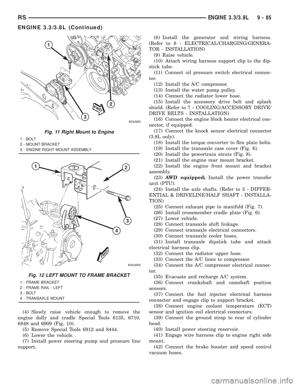
Fig. 11 Right Mount to Engine
1 - BOLT
2 - MOUNT BRACKET
3 - ENGINE RIGHT MOUNT ASSEMBLY
Fig. 12 LEFT MOUNT TO FRAME BRACKET
1 - FRAME BRACKET
2 - FRAME RAIL - LEFT
3 - BOLT
4 - TRANSAXLE MOUNT
RSENGINE 3.3/3.8L9-85
ENGINE 3.3/3.8L (Continued)
Page 2710 of 4284

(43) Connect the vacuum hoses to the throttle
body.
(44) Connect the EGR transducer electrical connec-
tor.
(45) Connect the TPS, IAC, and MAP sensor elec-
trical connectors.
(46) Connect throttle cables to throttle body.
(47) Install the radiator fans. (Refer to 7 - COOL-
ING/ENGINE/RADIATOR FAN - INSTALLATION)
(48) Connect the radiator upper hose.
(49) Connect the heater hoses. Remove pinch-off
pliers from the rear heater hoses, if equipped.
(50) Install the radiator upper support crossmem-
ber. (Refer to 23 - BODY/EXTERIOR/GRILLE OPEN-
ING REINFORCEMENT - INSTALLATION)
(51) Install the wiper module. (Refer to 8 - ELEC-
TRICAL/WIPERS/WASHERS/WIPER MODULE -
INSTALLATION)
(52) Connect the fuel line to fuel rail. (Refer to 14
- FUEL SYSTEM/FUEL DELIVERY/FUEL LINES -
STANDARD PROCEDURE)
(53) Install the air cleaner and hoses.
(54) Install new oil filter. Fill engine crankcase
with proper oil to correct level.
(55) Connect negative cable to battery.
(56) Fill the cooling system. (Refer to 7 - COOL-
ING - STANDARD PROCEDURE)
(57) Start engine and run until operating temper-
ature is reached.
(58) Adjust transmission linkage, if necessary.
SPECIFICATIONS
3.3/3.8L ENGINE
DESCRIPTION SPECIFICATION
General Specification
Type 60É V-6 Engine
Number of Cylinders 6
Displacement
Ð3.3L 3.3 Liters
(201 cu. in.)
Ð3.8L 3.8 Liters
(231 cu. in.)
Bore
Ð3.3L 93.0 mm
(3.66 in.)
Ð3.8L 96.0 mm
(3.779 in.)
DESCRIPTION SPECIFICATION
Stroke
Ð3.3L 81.0 mm
(3.188 in.)
Ð3.8L 87.0 mm
(3.425 in.)
Compression Ratio
Ð3.3L 9.35:1
Ð3.8L 9.6:1
Firing Order 1-2-3-4-5-6
Cylinder Number (Front
to Rear)
ÐFront Bank 2,4,6
ÐRear Bank 1,3,5
Compression PressureÐ
Minimum689.5 kPa
(100 psi)
Max. Variation Between
Cylinders25%
Cylinder Block
Cylinder Bore Diameter
(Standard)
Ð3.3L 92.993±93.007 mm
(3.661±3.6617 in.)
Ð3.8L 95.993±96.007 mm
(3.7792±3.780 in.)
Out-of-Round (Service
Limits)0.076 mm
(0.003 in.)
Taper (Service Limits) 0.051 mm
(0.002 in.)
Lifter Bore Diameter 22.980±23.010 mm
(0.905±0.906 in.)
Deck Surface Flatness
(Max.)0.1 mm
(0.004 in.)
Pistons
Piston Diameter
Ð3.3L ÐMeasured 39.8
mm (1.567 in.) from
piston top92.968±92.998 mm
(3.660±3.661 in.)
Ð3.8L ÐMeasured 33.01
mm (1.30 in.) from piston
top95.968±95.998 mm
(3.778±3.779 in.)
Clearance in Bore @
Size Location (New)-0.005±0.039 mm
(-0.0002±0.0015 in.)
9 - 86 ENGINE 3.3/3.8LRS
ENGINE 3.3/3.8L (Continued)
Page 2717 of 4284

AIR CLEANER ELEMENT
REMOVAL
(1) Unsnap 2 clips.
(2) Lift cover and pull toward the engine and
remove cover tabs from air box.
(3) Lift cover and remove the element (Fig. 13).
INSTALLATION
(1) Install the air filter element into air box (Fig.
11).
(2) Move cover so that the tabs insert into the air
box.
(3) Push cover down and snap the 2 clips.
AIR CLEANER HOUSING
REMOVAL
(1) Disconnect the negative battery cable.
(2) Disconnect the inlet air temperature sensor
(Fig. 14).
(3) Remove the inlet hose to throttle body.
(4) Remove the bolt for air box at upper radiator
cross member.(5) Pull air box up and off over the single locating
pin.
(6) Remove air box from vehicle
INSTALLATION
(1) Install air box into vehicle and onto the locat-
ing pin.
(2) Install bolt to hold air box to the upper radia-
tor cross member.
(3) Install the inlet hose to the throttle body.
(4) Connect the inlet air temperature sensor (Fig.
14).
(5) Connect the negative battery cable.
Cooling System Tester 7700
Combustion Leak Tester C-3685-A
Compression Test Adapter 8116
Fig. 13 AIR BOX COVER
Fig. 14 Inlet Air Temperature Sensor
RSENGINE 3.3/3.8L9-93
SPECIAL TOOLS (Continued)
Page 2755 of 4284

(4) Remove the load on the right engine mount by
carefully supporting the engine assembly with a floor
jack.
(5) Disconnect electrical harness support clips from
engine mount bracket.
(6) Remove the bolts attaching the engine mount
to the frame rail (Fig. 97).
(7) Remove the three bolts attaching the engine
mount to the engine bracket (Fig. 97).
(8) Remove the right engine mount (Fig. 97).
INSTALLATION
(1) Install engine bracket (if removed). Tighten
bolts to 33 N´m (24 ft. lbs.).(2) Position right engine mount and install frame
rail to mount bolts (Fig. 97). Tighten bolts to 68 N´m
(50 ft. lbs.).
(3) Install the mount to engine bracket bolts and
tighten to 54 N´m (40 ft. lbs.). (Fig. 97)
(4) Connect electrical harness support clips to
engine mount bracket.
(5) Remove jack from under engine.
(6) Connect make-up air hose to cylinder head
cover.
(7) Install air cleaner housing and element.
(8) Install air cleaner housing lid and clean air
tube to throttle body.
LUBRICATION
DESCRIPTION
The lubrication system is a full flow filtration pres-
sure feed type. The oil pump is mounted in the tim-
ing chain cover and is driven by the crankshaft
OPERATION
Oil from the oil pan is pumped by a internal gear
type oil pump directly coupled to the crankshaft. The
pressure is regulated by a relief valve located in the
timing chain cover. The oil is pumped through an oil
filter and feeds a main oil gallery. This oil gallery
feeds oil under pressure to the main and rod bear-
ings, camshaft bearings. Passages in the cylinder
block feed oil to the hydraulic lifters and rocker shaft
brackets which feeds the rocker arm pivots (Fig. 98).
DIAGNOSIS AND TESING - ENGINE OIL
PRESSURE
(1) Disconnect and remove oil pressure switch.
(Refer to 9 - ENGINE/LUBRICATION/OIL PRES-
SURE SENSOR/SWITCH - REMOVAL)
(2) Install Special Tools C-3292 Gauge with 8406
Adaptor (Fig. 99).
(3) Start engine and record oil pressure. Refer to
Oil Pressure in Engine Specifications for the correct
pressure. (Refer to 9 - ENGINE - SPECIFICATIONS)Fig. 97 Right Engine Mount
1 - RIGHT ENGINE MOUNT
2 - BOLT - MOUNT TO FRAME RAIL
3 - BOLT - MOUNT TO ENGINE
4 - ENGINE MOUNT BRACKET
5 - RIGHT FRAME RAIL
RSENGINE 3.3/3.8L9 - 131
RIGHT MOUNT (Continued)
Page 2761 of 4284

(8) Connect negative cable to battery.
(9) Fill crankcase with oil to proper level.
OIL PRESSURE RELIEF VALVE
REMOVAL
(1) Remove oil pan.
(2) Drill a 3.175 mm (1/8 in.) hole in the center of
the retainer cap (Fig. 109). Insert a self-threading
sheet metal screw into the cap.
(3) Using suitable pliers, remove cap and discard.
(4) Remove spring and relief valve (Fig. 109).
INSTALLATION
(1) Clean relief valve, spring and bore.
NOTE: Lubricate relief valve with clean engine oil
before installing.
(2) Install relief valve and spring into housing.
(3) Install new retainer cap until flush with seal-
ing surface.
(4) Install oil pan.
(5) Fill crankcase with proper oil to correct level.
OIL PRESSURE SENSOR/
SWITCH
DESCRIPTION
The engine oil pressure switch is located on the
lower left front side of the engine. It screws into the
oil filter adapter. The normally closed switch provides
an input through a single wire to the low pressure
indicator light on the instrument cluster.
Fig. 107 OIL PAN
1 - GASKET
2 - BOLT
3 - OIL PAN
4 - NUT
Fig. 108 Oil Pan Sealing
1 - SEALER LOCATIONS
Fig. 109 Oil Pressure Relief Valve
1 - RELIEF VALVE
2 - SPRING
3 - RETAINER CAP
RSENGINE 3.3/3.8L9 - 137
OIL PAN (Continued)