audio CHRYSLER VOYAGER 2001 Repair Manual
[x] Cancel search | Manufacturer: CHRYSLER, Model Year: 2001, Model line: VOYAGER, Model: CHRYSLER VOYAGER 2001Pages: 4284, PDF Size: 83.53 MB
Page 1816 of 4284
NOTE: The right remote radio switch back is white
in color. The left switch back is black in color. The
right/left remote radio switch orientation is with the
steering wheel installed, and driver in drivers seat.
INSTALLATION
WARNING:
ON VEHICLES EQUIPPED WITH AIRBAGS, REFER
TO ELECTRICAL, RESTRAINTS BEFORE ATTEMPT-
ING ANY STEERING WHEEL, STEERING COLUMN,
OR INSTRUMENT PANEL COMPONENT DIAGNOSIS
OR SERVICE. FAILURE TO TAKE THE PROPER
PRECAUTIONS COULD RESULT IN ACCIDENTAL
AIRBAG DEPLOYMENT AND POSSIBLE PERSONAL
INJURY.(1) Install remote radio switch to the steering
wheel.
(2) Install three screws securing steering wheel
rear cover.
(3) Connect the wire harness to the remote radio
switch.
(4) Install the steering wheel. Refer to STEERING/
COLUMN/STEERING WHEEL.
(5) Install the driver side airbag module. Refer to
ELECTRICAL/RESTRAINTS/DRIVER AIRBAG.
(6) Connect the battery negative cable.
8A - 12 AUDIORS
REMOTE SWITCHES (Continued)
Page 1817 of 4284
AUDIO
TABLE OF CONTENTS
page page
QUARTER GLASS INTEGRAL ANTENNA
DESCRIPTION............................1
OPERATION.............................1
DIAGNOSIS AND TESTING..................1
QUARTER GLASS INTEGRAL ANTENNA......1
ANTENNA MODULE
DESCRIPTION............................2OPERATION.............................2
DIAGNOSIS AND TESTING..................2
ANTENNA MODULE......................2
REMOVAL...............................2
INSTALLATION............................2
QUARTER GLASS INTEGRAL
ANTENNA
DESCRIPTION
The quarter glass integral antenna element is
bonded to the right rear quarter glass and is replaced
with the glass assembly only (Fig. 1).
OPERATION
The integral antenna receives RF (Radio Frequen-
cies) and sends them to the antenna module for
amplification.
DIAGNOSIS AND TESTING - QUARTER GLASS
INTEGRAL ANTENNA
The antenna grid pattern is divided into two sepa-
rate patterns. Each terminal connects to a separate
grid pattern, one for AM and the other for FM.
For circuit descriptions and diagrams, refer to the
appropriate wiring information. The wiring informa-
tion includes wiring diagrams, proper wire and con-
nector repair procedures, details of wire harness
routing and retention, connector pin-out information
and location views for the various wire harness con-
nectors, splices and grounds. To detect breaks in the
integral antenna elements, the following procedure is
required:
(1) Disconnect the antenna module connector from
the antenna terminals on the glass.
(2) Using an ohmmeter, place a lead on one of the
terminals and check each end of the grid pattern con-
nected to this terminal for continuity. If continuity is
not present, move one lead through the grid in pro-
gression starting at the terminal with the other lead
on the terminal until continuity is lost. Repeat pro-
cedure for the other terminal. A break in the antenna
grid can be repaired using a Mopar Rear Window
Defogger Repair Kit (Part Number 4267922) or
equivalent. (Refer to 8 - ELECTRICAL/HEATED
GLASS/WINDSHIELD GRID - STANDARD PROCE-
DURE).
Fig. 1 QUARTER GLASS INTEGRAL ANTENNA
1 - REAR QUARTER GLASS
2 - ANTENNA
RGAUDIO8Aa-1
Page 1818 of 4284
ANTENNA MODULE
DESCRIPTION
The antenna module is an electromagnetic circuit
component designed to capture and enhance RF
(Radio Frequency) signals in both the AM and FM
broadcast bands. The antenna module is mounted to
the right rear roof rail under the headliner. The mod-
ule is grounded through the mounting bracket and
fastener. The module has a two wire electrical con-
nector that connects to the integral radio antenna,located on the right rear quarter glass. There is also
an electrical connector for battery voltage and a coax
cable connector.OPERATION
The antenna module receives both AM and FM
radio signals supplied by the side window integral
radio antenna system and selectively amplifies them.
The amplified signal is then sent through the body
length coax cable to the radio input.
DIAGNOSIS AND TESTING - ANTENNA MODULE
CONDITION POSSIBLE CAUSES CORRECTION
NO AM RECEPTION,
WEAK FM RECEPTION1. Antenna module to antenna
connector open or disconnected.1. Repair open, reconnect
antenna module connector to
glass mounted antenna.
2. Coax open or disconnected. 2. Repair open, reconnect coax.
3. No battery power at antenna
module.3. Check fuse. if okay, repair
open in battery voltage circuit.
NO AM OR FM
RECEPTION1. Coax disconnected at radio. 1. Reconnect coax.
2. Coax shorted to ground. 2. Repair or Replace coax
WEAK OR NO AM/FM
RECEPTION1. Antenna Module faulty. 1. Substitute known good
module. If reception improves,
Antenna Module was faulty.
REMOVAL
(1) Disconnect and isolate the battery negative
cable.
(2) Lower headliner as necessary to access
antenna module (Fig. 2).
(3) Disconnect antenna coax cable lead and electri-
cal harness connector from antenna module.
(4) Disconnect the antenna module connector from
the quarter glass.
(5) Remove the mounting screw and the antenna
module.
INSTALLATION
(1) Install the antenna module and the mounting
fastener.
(2) Connect the antenna connector to the quarter
glass.
(3) Connect the antenna lead and electrical con-
nector to the antenna module.
(4) Raise and install headliner.
(5) Connect the battery negative cable.
Fig. 2 ANTENNA MODULE
1 - ANTENNA MODULE
2 - ANTENNA MODULE CONNECTOR
8Aa - 2 AUDIORG
Page 1869 of 4284
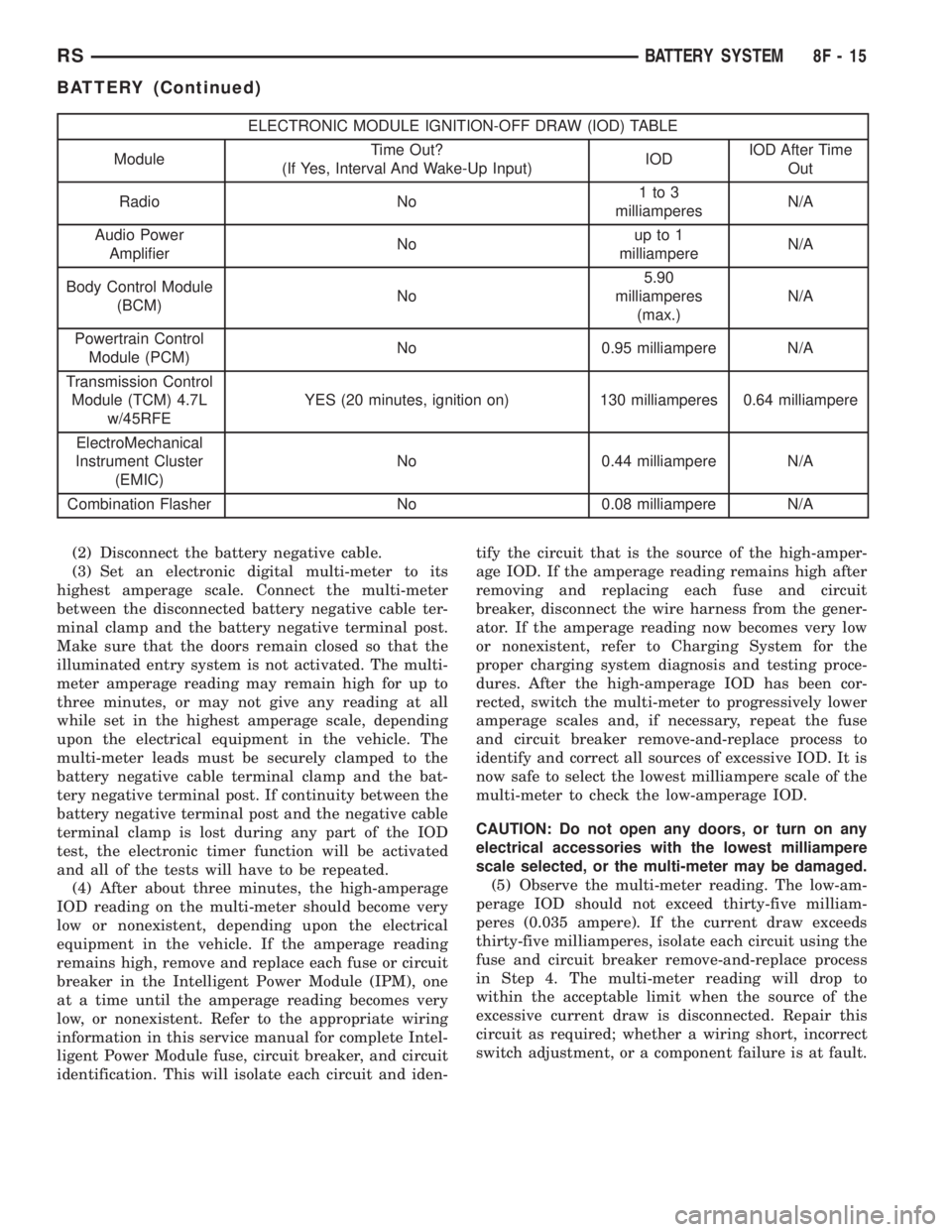
ELECTRONIC MODULE IGNITION-OFF DRAW (IOD) TABLE
ModuleTime Out?
(If Yes, Interval And Wake-Up Input)IODIOD After Time
Out
Radio No1to3
milliamperesN/A
Audio Power
AmplifierNoup to 1
milliampereN/A
Body Control Module
(BCM)No5.90
milliamperes
(max.)N/A
Powertrain Control
Module (PCM)No 0.95 milliampere N/A
Transmission Control
Module (TCM) 4.7L
w/45RFEYES (20 minutes, ignition on) 130 milliamperes 0.64 milliampere
ElectroMechanical
Instrument Cluster
(EMIC)No 0.44 milliampere N/A
Combination Flasher No 0.08 milliampere N/A
(2) Disconnect the battery negative cable.
(3) Set an electronic digital multi-meter to its
highest amperage scale. Connect the multi-meter
between the disconnected battery negative cable ter-
minal clamp and the battery negative terminal post.
Make sure that the doors remain closed so that the
illuminated entry system is not activated. The multi-
meter amperage reading may remain high for up to
three minutes, or may not give any reading at all
while set in the highest amperage scale, depending
upon the electrical equipment in the vehicle. The
multi-meter leads must be securely clamped to the
battery negative cable terminal clamp and the bat-
tery negative terminal post. If continuity between the
battery negative terminal post and the negative cable
terminal clamp is lost during any part of the IOD
test, the electronic timer function will be activated
and all of the tests will have to be repeated.
(4) After about three minutes, the high-amperage
IOD reading on the multi-meter should become very
low or nonexistent, depending upon the electrical
equipment in the vehicle. If the amperage reading
remains high, remove and replace each fuse or circuit
breaker in the Intelligent Power Module (IPM), one
at a time until the amperage reading becomes very
low, or nonexistent. Refer to the appropriate wiring
information in this service manual for complete Intel-
ligent Power Module fuse, circuit breaker, and circuit
identification. This will isolate each circuit and iden-tify the circuit that is the source of the high-amper-
age IOD. If the amperage reading remains high after
removing and replacing each fuse and circuit
breaker, disconnect the wire harness from the gener-
ator. If the amperage reading now becomes very low
or nonexistent, refer to Charging System for the
proper charging system diagnosis and testing proce-
dures. After the high-amperage IOD has been cor-
rected, switch the multi-meter to progressively lower
amperage scales and, if necessary, repeat the fuse
and circuit breaker remove-and-replace process to
identify and correct all sources of excessive IOD. It is
now safe to select the lowest milliampere scale of the
multi-meter to check the low-amperage IOD.
CAUTION: Do not open any doors, or turn on any
electrical accessories with the lowest milliampere
scale selected, or the multi-meter may be damaged.
(5) Observe the multi-meter reading. The low-am-
perage IOD should not exceed thirty-five milliam-
peres (0.035 ampere). If the current draw exceeds
thirty-five milliamperes, isolate each circuit using the
fuse and circuit breaker remove-and-replace process
in Step 4. The multi-meter reading will drop to
within the acceptable limit when the source of the
excessive current draw is disconnected. Repair this
circuit as required; whether a wiring short, incorrect
switch adjustment, or a component failure is at fault.
RSBATTERY SYSTEM8F-15
BATTERY (Continued)
Page 2030 of 4284
A eight-way power seat is standard on highline
models and optional on others. This option includes a
six-way adjustable seat cushion track and a two-way
power seat back.
The eight-way power seat is also available with the
heated seat and memory seat system that automati-
cally positions the power seat for two different driv-
ers. Refer toHeated Seat Systemfor more
information on the heated seat option. Refer toMem-
ory Systemin the Memory System section of this
group for more information on the memory system.
The power seat system includes the following com-
ponents:
²Power seat recliner
²Power seat switch
²Power seat track.
The power seat system with memory and heated
seat options includes the following components:
²Power seat recliner
²Power seat switch
²Power seat track.
²Memory Heated Seat Module (MHSM)
²Memory set switch
²Heated seat switch
²Electronic Vehicle Information Center (EVIC)
²Programmable Communications Interface (PCI)
data bus network
Refer to Wiring Diagrams for complete circuit dia-
grams. Following are general descriptions and opera-
tions for the major components in the power seat
system and memory seat system.
DESCRIPTION - MEMORY SEAT SYSTEM
An electronic memory and heated seat system is
available on some models. The memory system is
able to store and recall the driver side power seat
positions (including the power recliner position), and
both outside power mirror positions for two drivers.
For vehicles with a radio and heated / memory seat
system connected to the Programmable Communica-
tions Interface (PCI) data bus network, the memory
system is also able to store and recall radio station
presets for two drivers. The memory system also will
store and recall the last station listened to for each
driver, even if it is not one of the preset stations.
The memory system will automatically return to
all of these settings when the corresponding num-
bered and button of the memory switch on the driver
side seat side shield is depressed, or when the doors
are unlocked using the Remote Keyless Entry (RKE)
transmitter. A customer programmable feature of the
memory system allows the RKE recall of memory fea-
tures to be disabled in cases where there are more
than two drivers of the vehicle.
A Memory Heated Seat Module (MHSM) is used on
some models to control and integrate the many elec-tronic functions and features included in the memory
/ heated seat system.
The memory system includes the following compo-
nents:
²Heated seat switch
²Memory heated seat module (MHSM)
²Memory switch
²Position potentiometers on both outside power
mirrors
²Position potentiometers on the driver side power
seat track and power seat recliner motors.
²Radio receiver (if PCI data bus capable).
Certain functions and features of the memory system
rely upon resources shared with other electronic mod-
ules in the vehicle over the Programmable Communica-
tions Interface (PCI) J1850 data bus network. The PCI
data bus network allows the sharing of sensor informa-
tion. This helps to reduce wire harness complexity,
internal controller hardware, and component sensor cur-
rent loads. At the same time, this system provides
increased reliability, enhanced diagnostics, and allows
the addition of many new feature capabilities. For diag-
nosis of these electronic modules or of the PCI data bus
network, the use of a DRBtscan tool and the proper
Diagnostic Procedures manual are recommended.
The other electronic modules that may affect mem-
ory system operation are as follows:
²Body Control Module (BCM)- Refer toBody
Control Modulein Electronic Control Modules for
more information.
²
Electronic Vehicle Information Center (EVIC)
- Refer toElectronic Vehicle Information Center
in Overhead Console Systems for more information.
²Powertrain Control Module (PCM)- Refer to
Powertrain Control Modulein Electronic Control
Modules for more information.
²Radio Receiver- Refer toRadio Receiverin
Audio Systems for more information.
Refer toHeated Seat Systemfor more informa-
tion on the heated seat system. Refer toRemote
Keyless Entry Systemin Power Lock Systems for
more information on the RKE system. Refer to
Power Mirrorin Power Mirrors for more informa-
tion on the mirror position potentiometers. Refer to
Power Seat TrackandPower Seat Reclinerin
the Power Seat System section of this group for more
information on the driver side power seat position
potentiometers.
Refer toPower Seatin the Contents of Wiring
Diagrams for complete circuit diagrams. Following
are general descriptions of the remaining major com-
ponents in the factory-installed memory system.
OPERATION - POWER SEAT SYSTEM
The power seat system allows the driver and/or
front passenger seating positions to be adjusted elec-
8N - 50 POWER SEATSRS
POWER SEATS (Continued)
Page 2085 of 4284
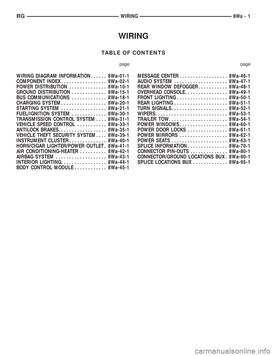
WIRING
TABLE OF CONTENTS
page page
WIRING DIAGRAM INFORMATION...... 8Wa-01-1
COMPONENT INDEX................. 8Wa-02-1
POWER DISTRIBUTION.............. 8Wa-10-1
GROUND DISTRIBUTION............. 8Wa-15-1
BUS COMMUNICATIONS............. 8Wa-18-1
CHARGING SYSTEM................. 8Wa-20-1
STARTING SYSTEM................. 8Wa-21-1
FUEL/IGNITION SYSTEM............. 8Wa-30-1
TRANSMISSION CONTROL SYSTEM.... 8Wa-31-1
VEHICLE SPEED CONTROL........... 8Wa-33-1
ANTILOCK BRAKES.................. 8Wa-35-1
VEHICLE THEFT SECURITY SYSTEM.... 8Wa-39-1
INSTRUMENT CLUSTER.............. 8Wa-40-1
HORN/CIGAR LIGHTER/POWER OUTLET . 8Wa-41-1
AIR CONDITIONING-HEATER.......... 8Wa-42-1
AIRBAG SYSTEM................... 8Wa-43-1
INTERIOR LIGHTING................. 8Wa-44-1
BODY CONTROL MODULE............ 8Wa-45-1MESSAGE CENTER.................. 8Wa-46-1
AUDIO SYSTEM.................... 8Wa-47-1
REAR WINDOW DEFOGGER........... 8Wa-48-1
OVERHEAD CONSOLE................ 8Wa-49-1
FRONT LIGHTING................... 8Wa-50-1
REAR LIGHTING.................... 8Wa-51-1
TURN SIGNALS..................... 8Wa-52-1
WIPERS........................... 8Wa-53-1
TRAILER TOW...................... 8Wa-54-1
POWER WINDOWS.................. 8Wa-60-1
POWER DOOR LOCKS............... 8Wa-61-1
POWER MIRRORS.................. 8Wa-62-1
POWER SEATS..................... 8Wa-63-1
SPLICE INFORMATION............... 8Wa-70-1
CONNECTOR PIN-OUTS.............. 8Wa-80-1
CONNECTOR/GROUND LOCATIONS BUX . 8Wa-90-1
SPLICE LOCATIONS BUX............. 8Wa-95-1 RGWIRING
8Wa-1
Page 2339 of 4284
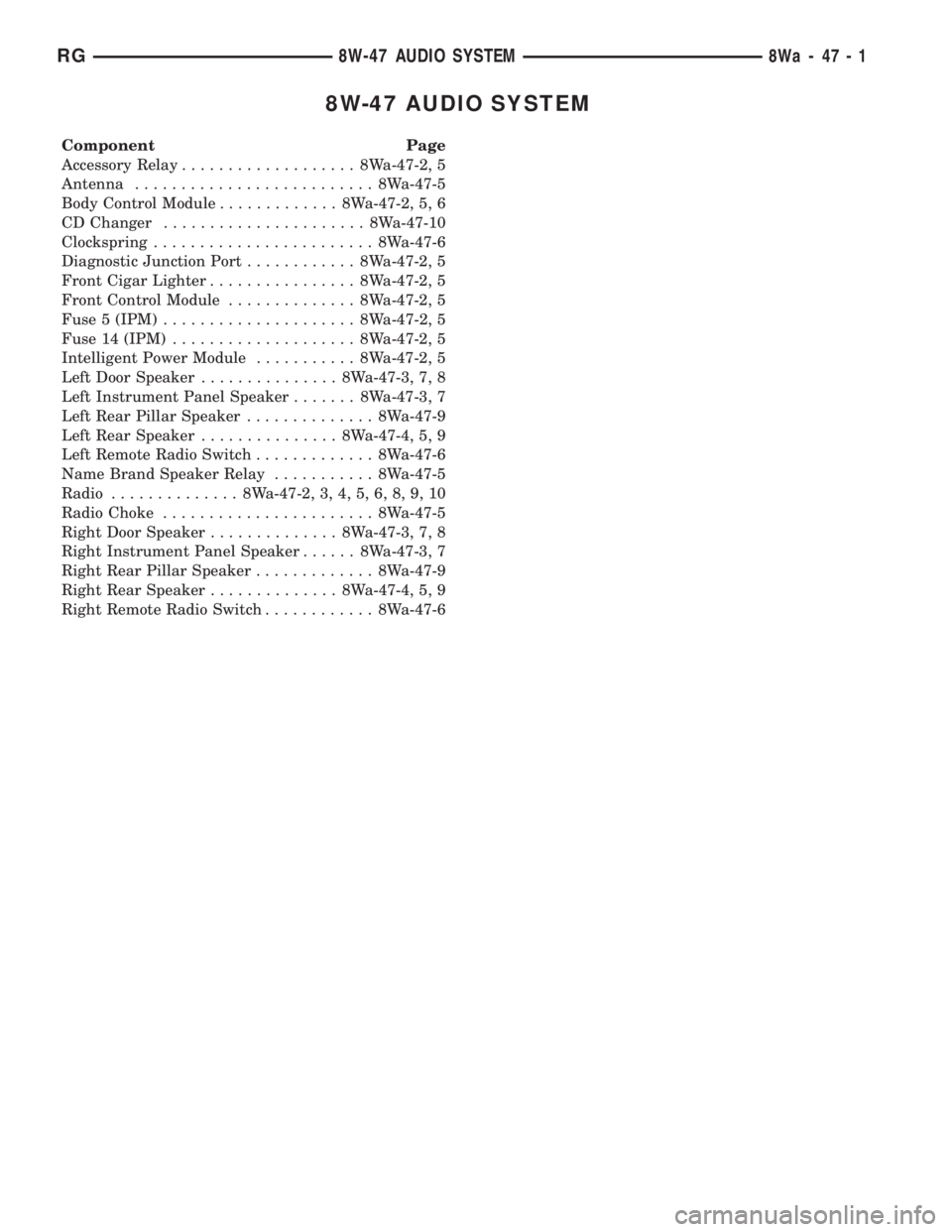
8W-47 AUDIO SYSTEM
Component Page
Accessory Relay................... 8Wa-47-2, 5
Antenna.......................... 8Wa-47-5
Body Control Module............. 8Wa-47-2, 5, 6
CD Changer...................... 8Wa-47-10
Clockspring........................ 8Wa-47-6
Diagnostic Junction Port............ 8Wa-47-2, 5
Front Cigar Lighter................ 8Wa-47-2, 5
Front Control Module.............. 8Wa-47-2, 5
Fuse 5 (IPM)..................... 8Wa-47-2, 5
Fuse 14 (IPM).................... 8Wa-47-2, 5
Intelligent Power Module........... 8Wa-47-2, 5
Left Door Speaker............... 8Wa-47-3, 7, 8
Left Instrument Panel Speaker....... 8Wa-47-3, 7
Left Rear Pillar Speaker.............. 8Wa-47-9
Left Rear Speaker............... 8Wa-47-4, 5, 9
Left Remote Radio Switch............. 8Wa-47-6
Name Brand Speaker Relay........... 8Wa-47-5
Radio.............. 8Wa-47-2, 3, 4, 5, 6, 8, 9, 10
Radio Choke....................... 8Wa-47-5
Right Door Speaker.............. 8Wa-47-3, 7, 8
Right Instrument Panel Speaker...... 8Wa-47-3, 7
Right Rear Pillar Speaker............. 8Wa-47-9
Right Rear Speaker.............. 8Wa-47-4, 5, 9
Right Remote Radio Switch............ 8Wa-47-6
RG8W-47 AUDIO SYSTEM8Wa-47-1
Page 2484 of 4284
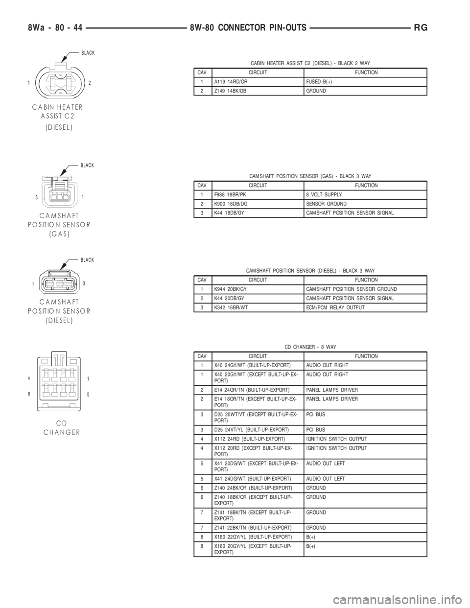
CABIN HEATER ASSIST C2 (DIESEL) - BLACK 2 WAY
CAV CIRCUIT FUNCTION
1 A119 14RD/OR FUSED B(+)
2 Z149 14BK/DB GROUND
CAMSHAFT POSITION SENSOR (GAS) - BLACK 3 WAY
CAV CIRCUIT FUNCTION
1 F888 18BR/PK 8 VOLT SUPPLY
2 K900 18DB/DG SENSOR GROUND
3 K44 18DB/GY CAMSHAFT POSITION SENSOR SIGNAL
CAMSHAFT POSITION SENSOR (DIESEL) - BLACK 3 WAY
CAV CIRCUIT FUNCTION
1 K944 20BK/GY CAMSHAFT POSITION SENSOR GROUND
2 K44 20DB/GY CAMSHAFT POSITION SENSOR SIGNAL
3 K342 16BR/WT ECM/PCM RELAY OUTPUT
CD CHANGER-8WAY
CAV CIRCUIT FUNCTION
1 X40 24GY/WT (BUILT-UP-EXPORT) AUDIO OUT RIGHT
1 X40 20GY/WT (EXCEPT BUILT-UP-EX-
PORT)AUDIO OUT RIGHT
2 E14 24OR/TN (BUILT-UP-EXPORT) PANEL LAMPS DRIVER
2 E14 18OR/TN (EXCEPT BUILT-UP-EX-
PORT)PANEL LAMPS DRIVER
3 D25 20WT/VT (EXCEPT BUILT-UP-EX-
PORT)PCI BUS
3 D25 24VT/YL (BUILT-UP-EXPORT) PCI BUS
4 X112 24RD (BUILT-UP-EXPORT) IGNITION SWITCH OUTPUT
4 X112 20RD (EXCEPT BUILT-UP-EX-
PORT)IGNITION SWITCH OUTPUT
5 X41 20DG/WT (EXCEPT BUILT-UP-EX-
PORT)AUDIO OUT LEFT
5 X41 24DG/WT (BUILT-UP-EXPORT) AUDIO OUT LEFT
6 Z140 24BK/OR (BUILT-UP-EXPORT) GROUND
6 Z140 18BK/OR (EXCEPT BUILT-UP-
EXPORT)GROUND
7 Z141 18BK/TN (EXCEPT BUILT-UP-
EXPORT)GROUND
7 Z141 22BK/TN (BUILT-UP-EXPORT) GROUND
8 X160 22GY/YL (BUILT-UP-EXPORT) B(+)
8 X160 20GY/YL (EXCEPT BUILT-UP-
EXPORT)B(+)
8Wa - 80 - 44 8W-80 CONNECTOR PIN-OUTSRG
Page 2543 of 4284
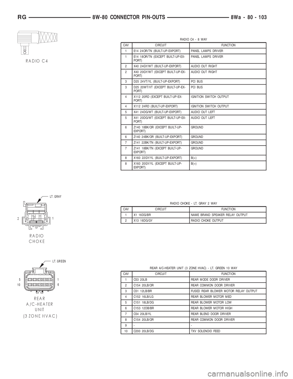
RADIO C4-8WAY
CAV CIRCUIT FUNCTION
1 E14 24OR/TN (BUILT-UP-EXPORT) PANEL LAMPS DRIVER
1 E14 18OR/TN (EXCEPT BUILT-UP-EX-
PORT)PANEL LAMPS DRIVER
2 X40 24GY/WT (BUILT-UP-EXPORT) AUDIO OUT RIGHT
2 X40 20GY/WT (EXCEPT BUILT-UP-EX-
PORT)AUDIO OUT RIGHT
3 D25 24VT/YL (BUILT-UP-EXPORT) PCI BUS
3 D25 20WT/VT (EXCEPT BUILT-UP-EX-
PORT)PCI BUS
4 X112 20RD (EXCEPT BUILT-UP-EX-
PORT)IGNITION SWITCH OUTPUT
4 X112 24RD (BUILT-UP-EXPORT) IGNITION SWITCH OUTPUT
5 X41 24DG/WT (BUILT-UP-EXPORT) AUDIO OUT LEFT
5 X41 20DG/WT (EXCEPT BUILT-UP-EX-
PORT)AUDIO OUT LEFT
6 Z140 18BK/OR (EXCEPT BUILT-UP-
EXPORT)GROUND
6 Z140 24BK/OR (BUILT-UP-EXPORT) GROUND
7 Z141 22BK/TN (BUILT-UP-EXPORT) GROUND
7 Z141 18BK/TN (EXCEPT BUILT-UP-
EXPORT)GROUND
8 X160 22GY/YL (BUILT-UP-EXPORT) B(+)
8 X160 20GY/YL (EXCEPT BUILT-UP-
EXPORT)B(+)
RADIO CHOKE - LT. GRAY 2 WAY
CAV CIRCUIT FUNCTION
1 X1 16DG/BR NAME BRAND SPEAKER RELAY OUTPUT
2 X13 16DG/GY RADIO CHOKE OUTPUT
REAR A/C-HEATER UNIT (3 ZONE HVAC) - LT. GREEN 10 WAY
CAV CIRCUIT FUNCTION
1 C53 20LB REAR MODE DOOR DRIVER
2 C154 20LB/OR REAR COMMON DOOR DRIVER
3 C51 12LB/BR FUSED REAR BLOWER MOTOR RELAY OUTPUT
4 C152 16LB/LG REAR BLOWER MOTOR MED
5 C151 18LB/DG REAR BLOWER MOTOR LOW
6 C153 12DB/BR REAR BLOWER MOTOR HIGH
7 C54 20LB/YL REAR BLEND DOOR DRIVER
8 C154 20LB/OR REAR COMMON DOOR DRIVER
9- -
10 C200 20LB/DG TXV SOLENOID FEED
RG8W-80 CONNECTOR PIN-OUTS8Wa - 80 - 103