sensor CHRYSLER VOYAGER 2001 Service Manual
[x] Cancel search | Manufacturer: CHRYSLER, Model Year: 2001, Model line: VOYAGER, Model: CHRYSLER VOYAGER 2001Pages: 4284, PDF Size: 83.53 MB
Page 4058 of 4284
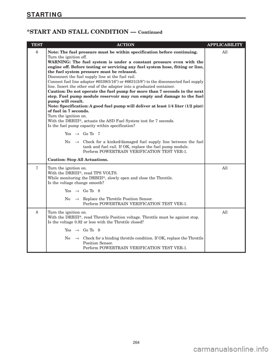
TEST ACTION APPLICABILITY
6Note: The fuel pressure must be within specification before continuing.
Turn the ignition off.
WARNING: The fuel system is under a constant pressure even with the
engine off. Before testing or servicing any fuel system hose, fitting or line,
the fuel system pressure must be released.
Disconnect the fuel supply line at the fuel rail.
Connect fuel line adapter #6539(5/169) or #6631(3/89) to the disconnected fuel supply
line. Insert the other end of the adapter into a graduated container.
Caution: Do not operate the fuel pump for more than 7 seconds in the next
step. Fuel pump module reservoir may run empty and damage to the fuel
pump will result.
Note: Specification: A good fuel pump will deliver at least 1/4 liter (1/2 pint)
of fuel in 7 seconds.
Turn the ignition on.
With the DRBIIIt, actuate the ASD Fuel System test for 7 seconds.
Is the fuel pump capacity within specification?All
Ye s®Go To 7
No®Check for a kinked/damaged fuel supply line between the fuel
tank and fuel rail. If OK, replace the fuel pump module.
Perform POWERTRAIN VERIFICATION TEST VER-1.
Caution: Stop All Actuations.
7 Turn the ignition on.
With the DRBIIIt, read TPS VOLTS.
While monitoring the DRBIIIt, slowly open and close the Throttle.
Is the voltage change smooth?All
Ye s®Go To 8
No®Replace the Throttle Position Sensor.
Perform POWERTRAIN VERIFICATION TEST VER-1.
8 Turn the ignition on.
With the DRBIIIt, read Throttle Position voltage. Throttle must be against stop.
Is the voltage 0.92 or less with the Throttle closed?All
Ye s®Go To 9
No®Check for a binding throttle condition. If OK, replace the Throttle
Position Sensor.
Perform POWERTRAIN VERIFICATION TEST VER-1.
264
STARTING
*START AND STALL CONDITION ÐContinued
Page 4059 of 4284

TEST ACTION APPLICABILITY
9Note: For this test to be valid, the thermostat must be operating correctly.
Note: This test works best if performed on a cold engine (cold soaked).
NOTE: If the vehicle was allow to sit over night with no engine start, coolant
temperature should be near ambient temperatures.
Turn the ignition on.
With the DRBIIIt, read the Engine Coolant Temperature value.
Note: If engine coolant temperature is above 82É C (180É F), allow the engine
to cool until 65É C (150É F) is reached.
Start the engine.
During engine warm-up, monitor the Engine Coolant Temperature value. The
temperature value change should be a smooth transition from start up to normal
operating temp 82É C (180É F). The value should reach at least 82É C (180É F).
Did the Engine Temperature value increase smoothly and did it reach at least 82É C
(180É F)?All
Ye s®Go To 10
No®Replace the Engine Coolant Temperature Sensor.
Perform POWERTRAIN VERIFICATION TEST VER-1.
10 The following additional items should be checked as a possible cause for a start and
stall condition.
Refer to any Technical Service Bulletins (TSB's) that may apply to the symptom.
Fuel must be free of contamination.
The exhaust system must be free of any restrictions.
The engine compression must be within specifications.
The engine valve timing must be within specifications.
The engine must be free from vacuum leaks.
The throttle body must be free of carbon buildup and dirt.
Do any of the above conditions exist?All
Ye s®Repair as necessary.
Perform POWERTRAIN VERIFICATION TEST VER-1.
No®Test Complete.
265
STARTING
*START AND STALL CONDITION ÐContinued
Page 4074 of 4284
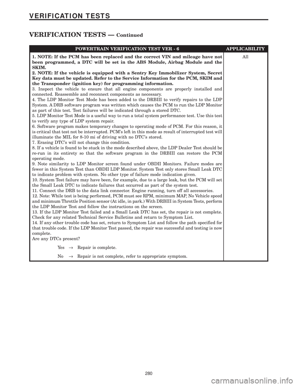
POWERTRAIN VERIFICATION TEST VER - 6 APPLICABILITY
1. NOTE: If the PCM has been replaced and the correct VIN and mileage have not
been programmed, a DTC will be set in the ABS Module, Airbag Module and the
SKIM.
2. NOTE: If the vehicle is equipped with a Sentry Key Immobilizer System, Secret
Key data must be updated. Refer to the Service Information for the PCM, SKIM and
the Transponder (ignition key) for programming information.
3. Inspect the vehicle to ensure that all engine components are properly installed and
connected. Reassemble and reconnect components as necessary.
4. The LDP Monitor Test Mode has been added to the DRBIII to verify repairs to the LDP
System. A DRB software program was written which causes the PCM to run the LDP Monitor
as part of this test. Test failures will be indicated through a stored DTC.
5. LDP Monitor Test Mode is a useful way to run a total system performance test. Use this test
to verify any type of LDP system repair.
6. Software program makes temporary changes to operating mode of PCM. For this reason, it
is critical that test not be interrupted. PCM's left in this mode as result of interrupted test will
illuminate the MIL for 8-10 mi of driving with no DTC's stored.
7. Erasing DTC's will not change this condition.
8. If a vehicle is found to be stuck in the mode described above, the LDP Dealer Test should be
re-run in its entirety so that the software program in the DRBIII can restore the PCM
operating mode.
9. Note similarity to LDP Monitor screen found under OBDII Monitors. Failure modes are
fewer in this System Test than OBDII LDP Monitor. System Test only stores Small Leak DTC
to indicate problem with system. No other type of failure mode indication given.
10. System Test failure may have been, for example, due to a large leak, but the PCM will set
the Small Leak DTC to indicate failures that occurred as part of the system test.
11. Connect the DRB to the data link connector. Engine running, turn off all accessories.
12. Note: While test is being performed, PCM must see RPM, minimum MAP, No Vehicle speed
and minimum Throttle Position sensor (At idle, in park.) With DRBIII in System Tests, perform
the LDP Monitor Test and follow the instructions on the screen.
13. If the LDP Monitor Test failed and a Small Leak DTC has set, the repair is not complete.
Check for any related Technical Service Bulletins and return to Symptom List.
14. If any other trouble code has set, return to Symptom List and follow the path specified for
that trouble code. If the LDP Monitor Test passed, the repair was successful and testing is now
complete.
Are any DTCs present?All
Ye s®Repair is complete.
No®Repair is not complete, refer to appropriate symptom.
280
VERIFICATION TESTS
VERIFICATION TESTS ÐContinued
Page 4080 of 4284
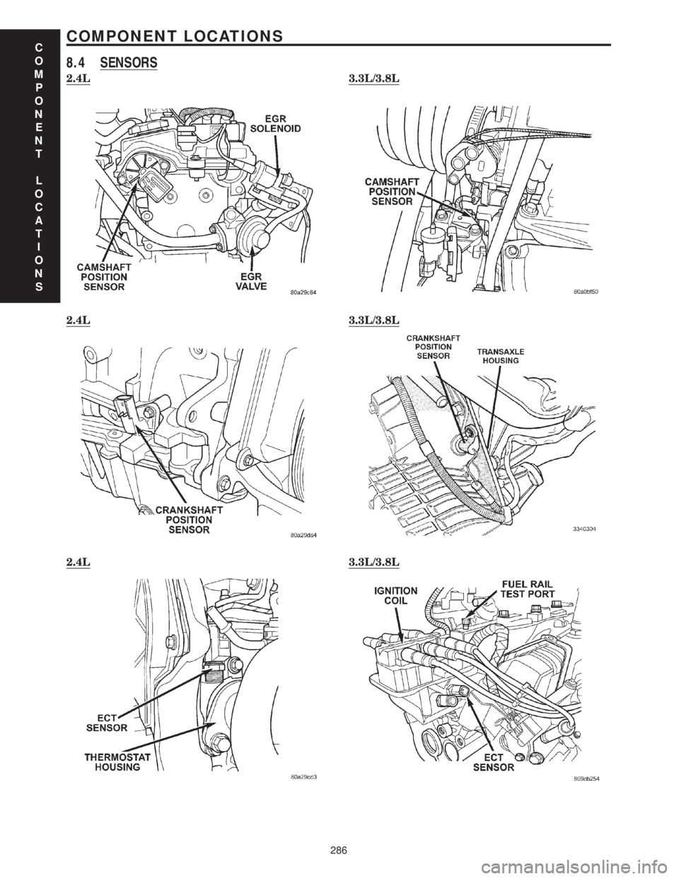
8.4 SENSORS
2.4L3.3L/3.8L
2.4L3.3L/3.8L
2.4L3.3L/3.8L
C
O
M
P
O
N
E
N
T
L
O
C
A
T
I
O
N
S
286
COMPONENT LOCATIONS
Page 4082 of 4284
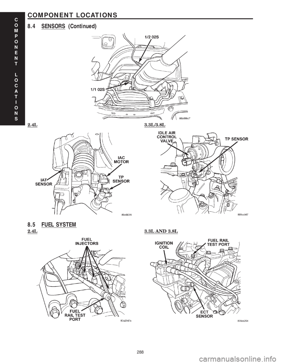
2.4L3.3L/3.8L
8.5 FUEL SYSTEM
2.4L3.3L AND 3.8L
C
O
M
P
O
N
E
N
T
L
O
C
A
T
I
O
N
S
288
COMPONENT LOCATIONS
8.4 SENSORS (Continued)
Page 4085 of 4284

9.0 CONNECTOR PINOUTS
A/C COMPRESSOR CLUTCH - LT. GRAY 2 WAYCAV CIRCUIT FUNCTION
1 C3 18DB/YL A/C COMPRESSOR CLUTCH RELAY OUTPUT
2 Z153 18BK/GY GROUND
A/C PRESSURE TRANSDUCER - GRAY 4 WAYCAV CIRCUIT FUNCTION
1 K900 18DB/DG SENSOR GROUND
2 F855 18PK/YL 5 VOLT SUPPLY
3 C18 18LB/BR A/C PRESSURE SIGNAL
4- -
AIR TEMPERATRUE SENSOR - BLACK 2 WAYCAV CIRCUIT FUNCTION
1 K21 18DB/LG INTAKE AIR TEMPERATURE SENSOR SIGNAL
2 K900 18DB/DG SENSOR GROUND
AMBIENT TEMPERATURE SENSOR - BLACK 2 WAYCAV CIRCUIT FUNCTION
1 G31 18VT/LG AMBIENT TEMPERATURE SENSOR SIGNAL
2 G931 18VT/BR AMBIENT TEMPERATURE SENSOR RETURN
C
O
N
N
E
C
T
O
R
P
I
N
O
U
T
S
291
CONNECTOR PINOUTS
Page 4086 of 4284
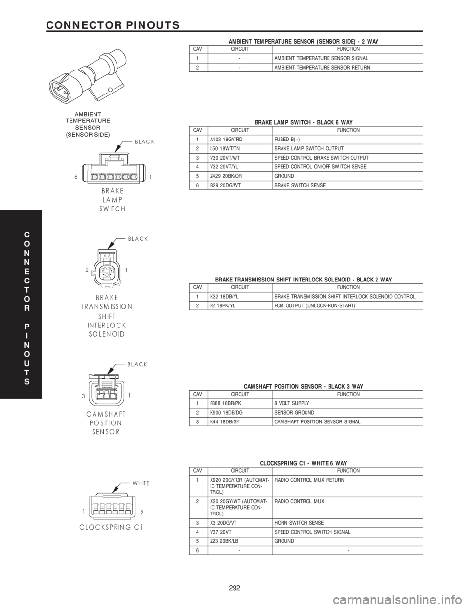
AMBIENT TEMPERATURE SENSOR (SENSOR SIDE)-2WAYCAV CIRCUIT FUNCTION
1 - AMBIENT TEMPERATURE SENSOR SIGNAL
2 - AMBIENT TEMPERATURE SENSOR RETURN
BRAKE LAMP SWITCH - BLACK 6 WAYCAV CIRCUIT FUNCTION
1 A103 18GY/RD FUSED B(+)
2 L50 18WT/TN BRAKE LAMP SWITCH OUTPUT
3 V30 20VT/WT SPEED CONTROL BRAKE SWITCH OUTPUT
4 V32 20VT/YL SPEED CONTROL ON/OFF SWITCH SENSE
5 Z429 20BK/OR GROUND
6 B29 20DG/WT BRAKE SWITCH SENSE
BRAKE TRANSMISSION SHIFT INTERLOCK SOLENOID - BLACK 2 WAYCAV CIRCUIT FUNCTION
1 K32 18DB/YL BRAKE TRANSMISSION SHIFT INTERLOCK SOLENOID CONTROL
2 F2 18PK/YL FCM OUTPUT (UNLOCK-RUN-START)
CAMSHAFT POSITION SENSOR - BLACK 3 WAYCAV CIRCUIT FUNCTION
1 F888 18BR/PK 8 VOLT SUPPLY
2 K900 18DB/DG SENSOR GROUND
3 K44 18DB/GY CAMSHAFT POSITION SENSOR SIGNAL
CLOCKSPRING C1 - WHITE 6 WAYCAV CIRCUIT FUNCTION
1 X920 20GY/OR (AUTOMAT-
IC TEMPERATURE CON-
TROL)RADIO CONTROL MUX RETURN
2 X20 20GY/WT (AUTOMAT-
IC TEMPERATURE CON-
TROL)RADIO CONTROL MUX
3 X3 20DG/VT HORN SWITCH SENSE
4 V37 20VT SPEED CONTROL SWITCH SIGNAL
5 Z23 20BK/LB GROUND
6- -
C
O
N
N
E
C
T
O
R
P
I
N
O
U
T
S
292
CONNECTOR PINOUTS
Page 4087 of 4284
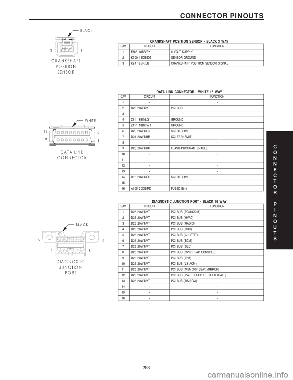
CRANKSHAFT POSITION SENSOR - BLACK 3 WAYCAV CIRCUIT FUNCTION
1 F888 18BR/PK 8 VOLT SUPPLY
2 K900 18DB/DG SENSOR GROUND
3 K24 18BR/LB CRANKSHAFT POSITION SENSOR SIGNAL
DATA LINK CONNECTOR - WHITE 16 WAYCAV CIRCUIT FUNCTION
1- -
2 D25 20WT/VT PCI BUS
3- -
4 Z11 18BK/LG GROUND
5 Z111 18BK/WT GROUND
6 D20 20WT/LG SCI RECEIVE
7 D21 20WT/BR SCI TRANSMIT
8- -
9 D23 20WT/BR FLASH PROGRAM ENABLE
10 - -
11 - -
12 - -
13 - -
14 D16 20WT/OR SCI RECEIVE
15 - -
16 A105 20DB/RD FUSED B(+)
DIAGNOSTIC JUNCTION PORT - BLACK 16 WAYCAV CIRCUIT FUNCTION
1 D25 20WT/VT PCI BUS (PCM/SKIM)
2 D25 20WT/VT PCI BUS (HVAC)
3 D25 20WT/VT PCI BUS (RADIO)
4 D25 20WT/VT PCI BUS (ORC)
5 D25 20WT/VT PCI BUS (CLUSTER)
6 D25 20WT/VT PCI BUS (BCM)
7 D25 20WT/VT PCI BUS (DLC)
8 D25 20WT/VT PCI BUS (OVERHEAD CONSOLE)
9 D25 20WT/VT PCI BUS (IPM)
10 D25 20WT/VT PCI BUS (LSIACM)
11 D25 20WT/VT PCI BUS (MEMORY SEAT/MIRROR)
12 D25 20WT/VT PCI BUS (PWR DOOR/ LT, RT LIFTGATE)
13 D25 20WT/VT PCI BUS (RSIACM)
14 - -
15 - -
16 - -
C
O
N
N
E
C
T
O
R
P
I
N
O
U
T
S
293
CONNECTOR PINOUTS
Page 4088 of 4284
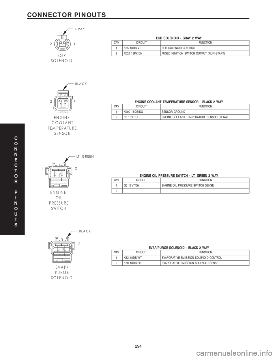
EGR SOLENOID - GRAY 2 WAYCAV CIRCUIT FUNCTION
1 K35 18DB/VT EGR SOLENOID CONTROL
2 F202 18PK/GY FUSED IGNITION SWITCH OUTPUT (RUN-START)
ENGINE COOLANT TEMPERATURE SENSOR - BLACK 2 WAYCAV CIRCUIT FUNCTION
1 K900 18DB/DG SENSOR GROUND
2 K2 18VT/OR ENGINE COOLANT TEMPERATURE SENSOR SIGNAL
ENGINE OIL PRESSURE SWITCH - LT. GREEN 2 WAYCAV CIRCUIT FUNCTION
1 G6 16VT/GY ENGINE OIL PRESSURE SWITCH SENSE
2- -
EVAP/PURGE SOLENOID - BLACK 2 WAYCAV CIRCUIT FUNCTION
1 K52 18DB/WT EVAPORATIVE EMISSION SOLENOID CONTROL
2 K70 18DB/BR EVAPORATIVE EMISSION SOLENOID SENSE
C
O
N
N
E
C
T
O
R
P
I
N
O
U
T
S
294
CONNECTOR PINOUTS
Page 4090 of 4284
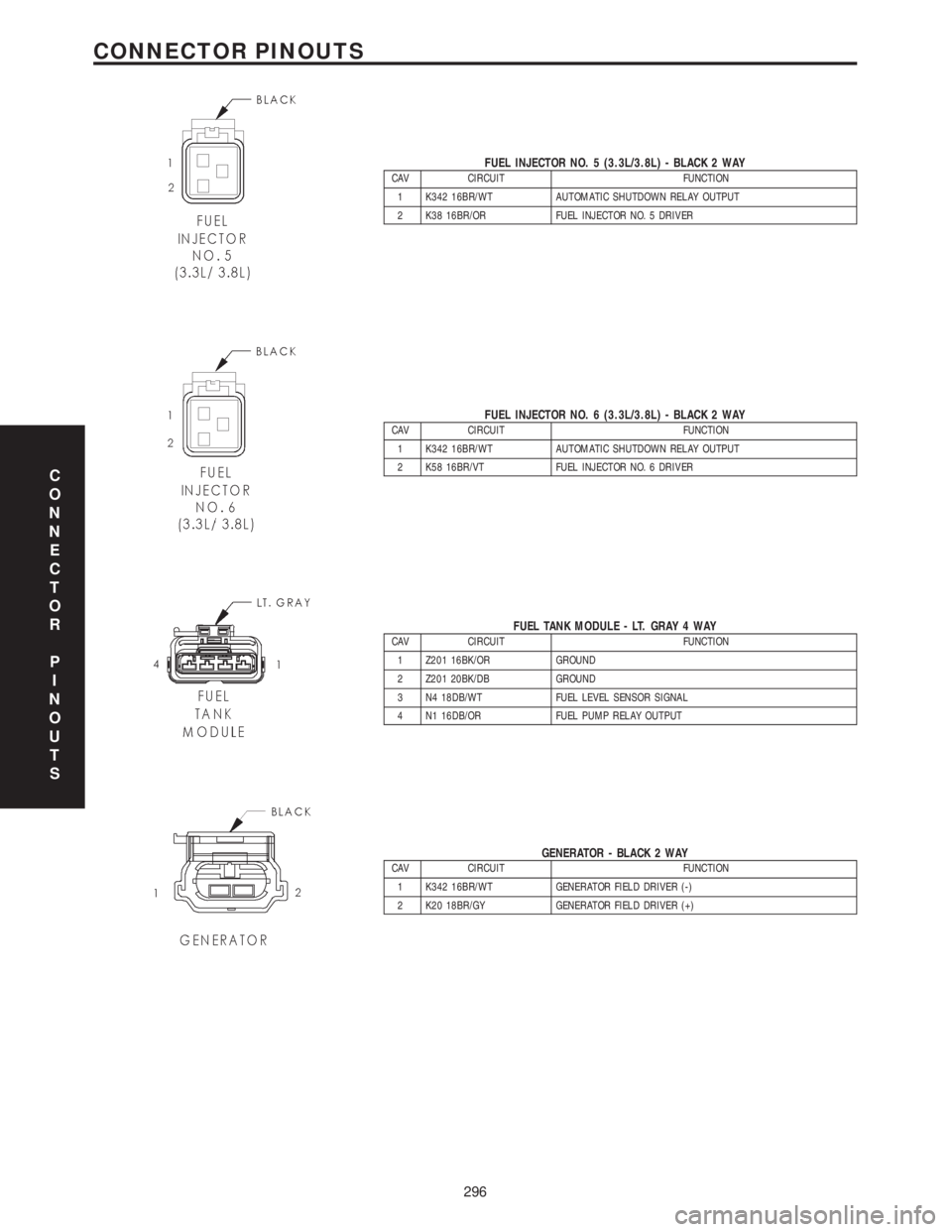
FUEL INJECTOR NO. 5 (3.3L/3.8L) - BLACK 2 WAYCAV CIRCUIT FUNCTION
1 K342 16BR/WT AUTOMATIC SHUTDOWN RELAY OUTPUT
2 K38 16BR/OR FUEL INJECTOR NO. 5 DRIVER
FUEL INJECTOR NO. 6 (3.3L/3.8L) - BLACK 2 WAYCAV CIRCUIT FUNCTION
1 K342 16BR/WT AUTOMATIC SHUTDOWN RELAY OUTPUT
2 K58 16BR/VT FUEL INJECTOR NO. 6 DRIVER
FUEL TANK MODULE - LT. GRAY 4 WAYCAV CIRCUIT FUNCTION
1 Z201 16BK/OR GROUND
2 Z201 20BK/DB GROUND
3 N4 18DB/WT FUEL LEVEL SENSOR SIGNAL
4 N1 16DB/OR FUEL PUMP RELAY OUTPUT
GENERATOR - BLACK 2 WAYCAV CIRCUIT FUNCTION
1 K342 16BR/WT GENERATOR FIELD DRIVER (-)
2 K20 18BR/GY GENERATOR FIELD DRIVER (+)
C
O
N
N
E
C
T
O
R
P
I
N
O
U
T
S
296
CONNECTOR PINOUTS