ESP CHRYSLER VOYAGER 2001 Service Manual
[x] Cancel search | Manufacturer: CHRYSLER, Model Year: 2001, Model line: VOYAGER, Model: CHRYSLER VOYAGER 2001Pages: 4284, PDF Size: 83.53 MB
Page 11 of 4284
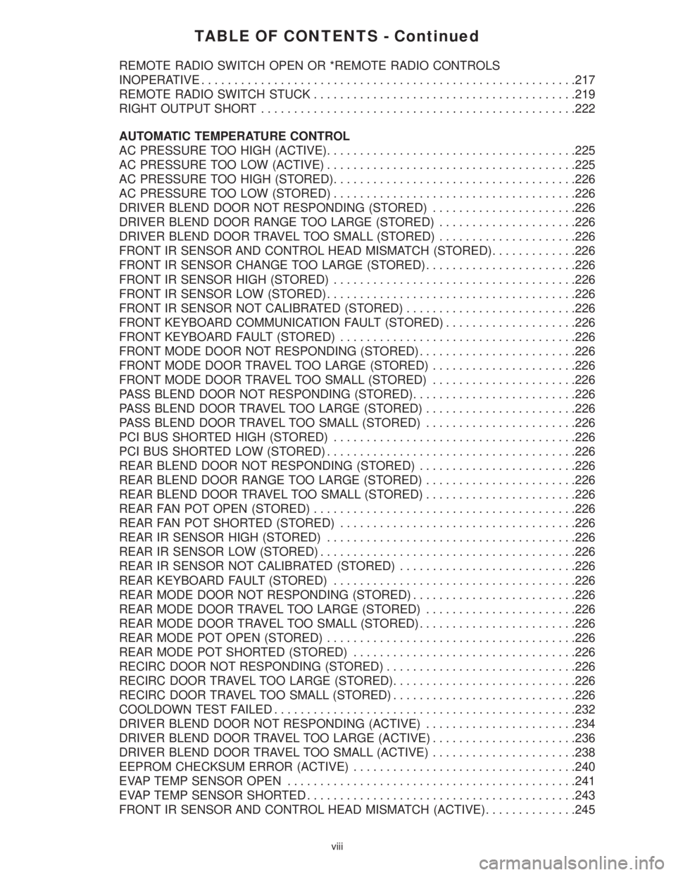
TABLE OF CONTENTS - Continued
REMOTE RADIO SWITCH OPEN OR *REMOTE RADIO CONTROLS
INOPERATIVE.........................................................217
REMOTE RADIO SWITCH STUCK........................................219
RIGHT OUTPUT SHORT................................................222
AUTOMATIC TEMPERATURE CONTROL
AC PRESSURE TOO HIGH (ACTIVE)......................................225
AC PRESSURE TOO LOW (ACTIVE)......................................225
AC PRESSURE TOO HIGH (STORED).....................................226
AC PRESSURE TOO LOW (STORED).....................................226
DRIVER BLEND DOOR NOT RESPONDING (STORED)......................226
DRIVER BLEND DOOR RANGE TOO LARGE (STORED).....................226
DRIVER BLEND DOOR TRAVEL TOO SMALL (STORED).....................226
FRONT IR SENSOR AND CONTROL HEAD MISMATCH (STORED).............226
FRONT IR SENSOR CHANGE TOO LARGE (STORED).......................226
FRONT IR SENSOR HIGH (STORED).....................................226
FRONT IR SENSOR LOW (STORED)......................................226
FRONT IR SENSOR NOT CALIBRATED (STORED)..........................226
FRONT KEYBOARD COMMUNICATION FAULT (STORED)....................226
FRONT KEYBOARD FAULT (STORED)....................................226
FRONT MODE DOOR NOT RESPONDING (STORED)........................226
FRONT MODE DOOR TRAVEL TOO LARGE (STORED)......................226
FRONT MODE DOOR TRAVEL TOO SMALL (STORED)......................226
PASS BLEND DOOR NOT RESPONDING (STORED).........................226
PASS BLEND DOOR TRAVEL TOO LARGE (STORED).......................226
PASS BLEND DOOR TRAVEL TOO SMALL (STORED).......................226
PCI BUS SHORTED HIGH (STORED).....................................226
PCI BUS SHORTED LOW (STORED)......................................226
REAR BLEND DOOR NOT RESPONDING (STORED)........................226
REAR BLEND DOOR RANGE TOO LARGE (STORED).......................226
REAR BLEND DOOR TRAVEL TOO SMALL (STORED).......................226
REAR FAN POT OPEN (STORED)........................................226
REAR FAN POT SHORTED (STORED)....................................226
REAR IR SENSOR HIGH (STORED)......................................226
REAR IR SENSOR LOW (STORED).......................................226
REAR IR SENSOR NOT CALIBRATED (STORED)...........................226
REAR KEYBOARD FAULT (STORED).....................................226
REAR MODE DOOR NOT RESPONDING (STORED).........................226
REAR MODE DOOR TRAVEL TOO LARGE (STORED).......................226
REAR MODE DOOR TRAVEL TOO SMALL (STORED)........................226
REAR MODE POT OPEN (STORED)......................................226
REAR MODE POT SHORTED (STORED)..................................226
RECIRC DOOR NOT RESPONDING (STORED).............................226
RECIRC DOOR TRAVEL TOO LARGE (STORED)............................226
RECIRC DOOR TRAVEL TOO SMALL (STORED)............................226
COOLDOWN TEST FAILED..............................................232
DRIVER BLEND DOOR NOT RESPONDING (ACTIVE).......................234
DRIVER BLEND DOOR TRAVEL TOO LARGE (ACTIVE)......................236
DRIVER BLEND DOOR TRAVEL TOO SMALL (ACTIVE)......................238
EEPROM CHECKSUM ERROR (ACTIVE)..................................240
EVAP TEMP SENSOR OPEN............................................241
EVAP TEMP SENSOR SHORTED.........................................243
FRONT IR SENSOR AND CONTROL HEAD MISMATCH (ACTIVE)..............245
viii
Page 12 of 4284
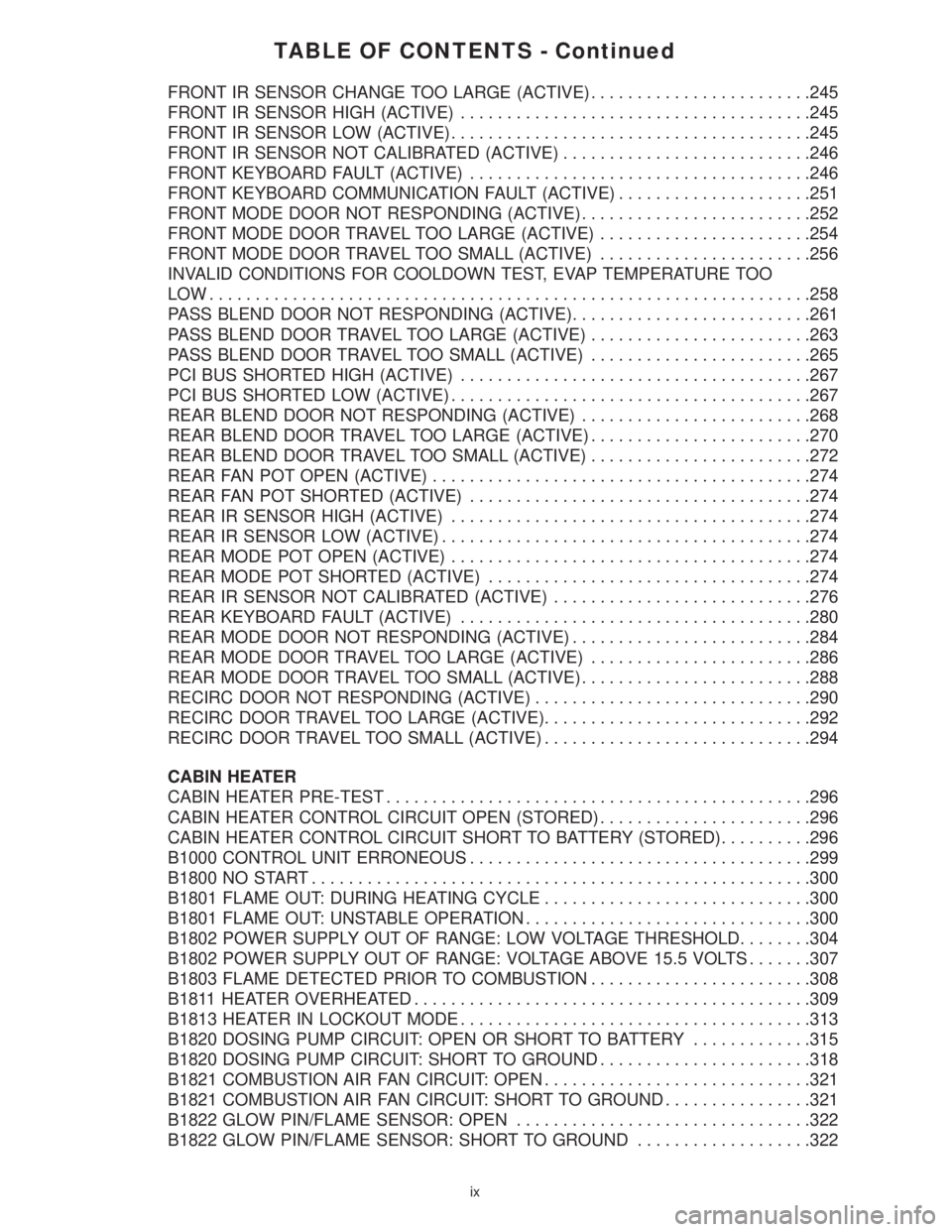
TABLE OF CONTENTS - Continued
FRONT IR SENSOR CHANGE TOO LARGE (ACTIVE)........................245
FRONT IR SENSOR HIGH (ACTIVE)......................................245
FRONT IR SENSOR LOW (ACTIVE).......................................245
FRONT IR SENSOR NOT CALIBRATED (ACTIVE)...........................246
FRONT KEYBOARD FAULT (ACTIVE).....................................246
FRONT KEYBOARD COMMUNICATION FAULT (ACTIVE).....................251
FRONT MODE DOOR NOT RESPONDING (ACTIVE).........................252
FRONT MODE DOOR TRAVEL TOO LARGE (ACTIVE).......................254
FRONT MODE DOOR TRAVEL TOO SMALL (ACTIVE).......................256
INVALID CONDITIONS FOR COOLDOWN TEST, EVAP TEMPERATURE TOO
LOW.................................................................258
PASS BLEND DOOR NOT RESPONDING (ACTIVE)..........................261
PASS BLEND DOOR TRAVEL TOO LARGE (ACTIVE)........................263
PASS BLEND DOOR TRAVEL TOO SMALL (ACTIVE)........................265
PCI BUS SHORTED HIGH (ACTIVE)......................................267
PCI BUS SHORTED LOW (ACTIVE).......................................267
REAR BLEND DOOR NOT RESPONDING (ACTIVE).........................268
REAR BLEND DOOR TRAVEL TOO LARGE (ACTIVE)........................270
REAR BLEND DOOR TRAVEL TOO SMALL (ACTIVE)........................272
REAR FAN POT OPEN (ACTIVE).........................................274
REAR FAN POT SHORTED (ACTIVE).....................................274
REAR IR SENSOR HIGH (ACTIVE).......................................274
REAR IR SENSOR LOW (ACTIVE)........................................274
REAR MODE POT OPEN (ACTIVE).......................................274
REAR MODE POT SHORTED (ACTIVE)...................................274
REAR IR SENSOR NOT CALIBRATED (ACTIVE)............................276
REAR KEYBOARD FAULT (ACTIVE)......................................280
REAR MODE DOOR NOT RESPONDING (ACTIVE)..........................284
REAR MODE DOOR TRAVEL TOO LARGE (ACTIVE)........................286
REAR MODE DOOR TRAVEL TOO SMALL (ACTIVE).........................288
RECIRC DOOR NOT RESPONDING (ACTIVE)..............................290
RECIRC DOOR TRAVEL TOO LARGE (ACTIVE).............................292
RECIRC DOOR TRAVEL TOO SMALL (ACTIVE).............................294
CABIN HEATER
CABIN HEATER PRE-TEST..............................................296
CABIN HEATER CONTROL CIRCUIT OPEN (STORED).......................296
CABIN HEATER CONTROL CIRCUIT SHORT TO BATTERY (STORED)..........296
B1000 CONTROL UNIT ERRONEOUS.....................................299
B1800 NO START......................................................300
B1801 FLAME OUT: DURING HEATING CYCLE.............................300
B1801 FLAME OUT: UNSTABLE OPERATION...............................300
B1802 POWER SUPPLY OUT OF RANGE: LOW VOLTAGE THRESHOLD........304
B1802 POWER SUPPLY OUT OF RANGE: VOLTAGE ABOVE 15.5 VOLTS.......307
B1803 FLAME DETECTED PRIOR TO COMBUSTION........................308
B1811 HEATER OVERHEATED...........................................309
B1813 HEATER IN LOCKOUT MODE......................................313
B1820 DOSING PUMP CIRCUIT: OPEN OR SHORT TO BATTERY.............315
B1820 DOSING PUMP CIRCUIT: SHORT TO GROUND.......................318
B1821 COMBUSTION AIR FAN CIRCUIT: OPEN.............................321
B1821 COMBUSTION AIR FAN CIRCUIT: SHORT TO GROUND................321
B1822 GLOW PIN/FLAME SENSOR: OPEN................................322
B1822 GLOW PIN/FLAME SENSOR: SHORT TO GROUND...................322
ix
Page 13 of 4284
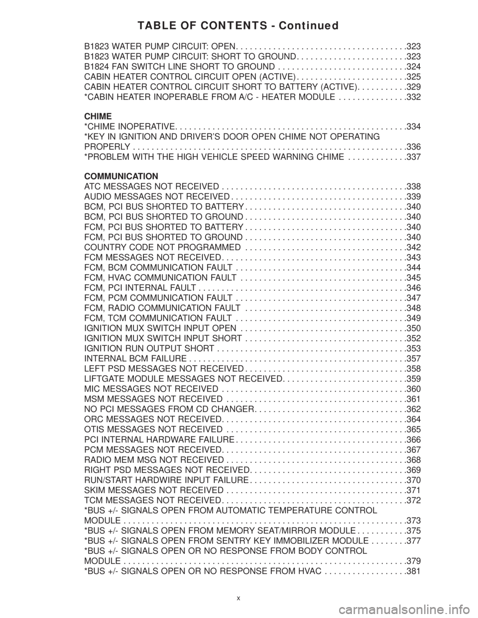
TABLE OF CONTENTS - Continued
B1823 WATER PUMP CIRCUIT: OPEN.....................................323
B1823 WATER PUMP CIRCUIT: SHORT TO GROUND........................323
B1824 FAN SWITCH LINE SHORT TO GROUND............................324
CABIN HEATER CONTROL CIRCUIT OPEN (ACTIVE)........................325
CABIN HEATER CONTROL CIRCUIT SHORT TO BATTERY (ACTIVE)...........329
*CABIN HEATER INOPERABLE FROM A/C - HEATER MODULE...............332
CHIME
*CHIME INOPERATIVE..................................................334
*KEY IN IGNITION AND DRIVER'S DOOR OPEN CHIME NOT OPERATING
PROPERLY...........................................................336
*PROBLEM WITH THE HIGH VEHICLE SPEED WARNING CHIME.............337
COMMUNICATION
ATC MESSAGES NOT RECEIVED........................................338
AUDIO MESSAGES NOT RECEIVED......................................339
BCM, PCI BUS SHORTED TO BATTERY...................................340
BCM, PCI BUS SHORTED TO GROUND...................................340
FCM, PCI BUS SHORTED TO BATTERY...................................340
FCM, PCI BUS SHORTED TO GROUND...................................340
COUNTRY CODE NOT PROGRAMMED...................................342
FCM MESSAGES NOT RECEIVED........................................343
FCM, BCM COMMUNICATION FAULT.....................................344
FCM, HVAC COMMUNICATION FAULT....................................345
FCM, PCI INTERNAL FAULT.............................................346
FCM, PCM COMMUNICATION FAULT.....................................347
FCM, RADIO COMMUNICATION FAULT...................................348
FCM, TCM COMMUNICATION FAULT.....................................349
IGNITION MUX SWITCH INPUT OPEN....................................350
IGNITION MUX SWITCH INPUT SHORT...................................352
IGNITION RUN OUTPUT SHORT.........................................353
INTERNAL BCM FAILURE...............................................357
LEFT PSD MESSAGES NOT RECEIVED...................................358
LIFTGATE MODULE MESSAGES NOT RECEIVED...........................359
MIC MESSAGES NOT RECEIVED........................................360
MSM MESSAGES NOT RECEIVED.......................................361
NO PCI MESSAGES FROM CD CHANGER.................................362
ORC MESSAGES NOT RECEIVED........................................364
OTIS MESSAGES NOT RECEIVED.......................................365
PCI INTERNAL HARDWARE FAILURE.....................................366
PCM MESSAGES NOT RECEIVED........................................367
RADIO MEM MSG NOT RECEIVED.......................................368
RIGHT PSD MESSAGES NOT RECEIVED..................................369
RUN/START HARDWIRE INPUT FAILURE..................................370
SKIM MESSAGES NOT RECEIVED.......................................371
TCM MESSAGES NOT RECEIVED........................................372
*BUS +/- SIGNALS OPEN FROM AUTOMATIC TEMPERATURE CONTROL
MODULE.............................................................373
*BUS +/- SIGNALS OPEN FROM MEMORY SEAT/MIRROR MODULE...........375
*BUS +/- SIGNALS OPEN FROM SENTRY KEY IMMOBILIZER MODULE........377
*BUS +/- SIGNALS OPEN OR NO RESPONSE FROM BODY CONTROL
MODULE.............................................................379
*BUS +/- SIGNALS OPEN OR NO RESPONSE FROM HVAC..................381
x
Page 14 of 4284
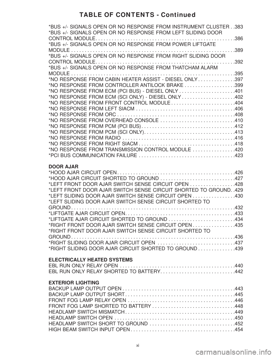
TABLE OF CONTENTS - Continued
*BUS +/- SIGNALS OPEN OR NO RESPONSE FROM INSTRUMENT CLUSTER . .383
*BUS +/- SIGNALS OPEN OR NO RESPONSE FROM LEFT SLIDING DOOR
CONTROL MODULE....................................................386
*BUS +/- SIGNALS OPEN OR NO RESPONSE FROM POWER LIFTGATE
MODULE.............................................................389
*BUS +/- SIGNALS OPEN OR NO RESPONSE FROM RIGHT SLIDING DOOR
CONTROL MODULE....................................................392
*BUS +/- SIGNALS OPEN OR NO RESPONSE FROM THATCHAM ALARM
MODULE.............................................................395
*NO RESPONSE FROM CABIN HEATER ASSIST - DIESEL ONLY..............397
*NO RESPONSE FROM CONTROLLER ANTILOCK BRAKE...................399
*NO RESPONSE FROM ECM (PCI BUS) - DIESEL ONLY.....................401
*NO RESPONSE FROM ECM (SCI ONLY) - DIESEL ONLY....................402
*NO RESPONSE FROM FRONT CONTROL MODULE........................404
*NO RESPONSE FROM LEFT SIACM.....................................406
*NO RESPONSE FROM ORC............................................408
*NO RESPONSE FROM OVERHEAD CONSOLE............................410
*NO RESPONSE FROM PCM (PCI BUS)...................................412
*NO RESPONSE FROM PCM (SCI ONLY)..................................413
*NO RESPONSE FROM RADIO..........................................416
*NO RESPONSE FROM RIGHT SIACM....................................418
*NO RESPONSE FROM TRANSMISSION CONTROL MODULE................420
*PCI BUS COMMUNICATION FAILURE....................................423
DOOR AJAR
*HOOD AJAR CIRCUIT OPEN............................................426
*HOOD AJAR CIRCUIT SHORTED TO GROUND............................427
*LEFT FRONT DOOR AJAR SWITCH SENSE CIRCUIT OPEN.................428
*LEFT FRONT DOOR AJAR SWITCH SENSE CIRCUIT SHORTED TO GROUND. .429
*LEFT SLIDING DOOR AJAR SWITCH SENSE CIRCUIT OPEN................430
*LEFT SLIDING DOOR AJAR SWITCH SENSE CIRCUIT SHORTED TO
GROUND.............................................................432
*LIFTGATE AJAR CIRCUIT OPEN.........................................433
*LIFTGATE AJAR CIRCUIT SHORTED TO GROUND.........................434
*RIGHT FRONT DOOR AJAR SWITCH SENSE CIRCUIT OPEN................435
*RIGHT FRONT DOOR AJAR SWITCH SENSE CIRCUIT SHORTED TO
GROUND.............................................................436
*RIGHT SLIDING DOOR AJAR CIRCUIT OPEN.............................437
*RIGHT SLIDING DOOR AJAR CIRCUIT SHORTED TO GROUND..............439
ELECTRICALLY HEATED SYSTEMS
EBL RUN ONLY RELAY OPEN...........................................440
EBL RUN ONLY RELAY SHORTED TO BATTERY............................442
EXTERIOR LIGHTING
BACKUP LAMP OUTPUT OPEN..........................................443
BACKUP LAMP OUTPUT SHORT.........................................445
FRONT FOG LAMP RELAY OPEN........................................446
FRONT FOG LAMP SHORTED TO BATTERY...............................448
HEADLAMP SWITCH MISMATCH.........................................449
HEADLAMP SWITCH OPEN.............................................450
HEADLAMP SWITCH SHORT TO GROUND................................452
HIGH BEAM SWITCH INPUT OPEN.......................................454
xi
Page 30 of 4284
1.0 INTRODUCTION
The procedures contained in this manual include
all the specifications, instructions and graphics
needed to diagnose 2001 body system problems. The
diagnostics in this manual are based on the failure
condition or symptom being present at the time of
diagnosis.
Please follow the recommendations below when
choosing your diagnostic path.
1. First make sure the DRBIIItis communicating
with the appropriate modules; i.e., if the
DRBIIItdisplays a ªNo Responseº or a ªBus6
Signals Openº condition, you must diagnose that
first.
2. Read DTC's (diagnostic trouble codes) with the
DRBIIIt.
3. If no DTC's are present, identify the customer
complaint.
4. Once the DTC or customer complaint is identi-
fied, locate the matching test in the Table of
Contents and begin to diagnose the symptom.
All component location views are in Section 8.0. All
connector pinouts are in Section 9.0. All schematics
are in Section 10.0. All Charts and Graphs are in
Section 11.0.
An * placed before the symptom description indi-
cated a customer complaint.
When repairs are required, refer to the appropri-
ate service information for the proper removal and
repair procedure.
Diagnostic procedures change every year. New
diagnostic systems may be added: carryover systems
may be enhanced. READ THIS MANUAL BEFORE
TRYING TO DIAGNOSE A VEHICLE DIAGNOS-
TIC TROUBLE CODE. It is recommended that you
review the entire manual to become familiar with all
the new and changed diagnostic procedures.
This book reflects many suggested changes from
readers of past issues. After using this book, if you
have any comments or suggestions, please fill out
the form in the back of this book and mail it back to
us.
1.1 SYSTEM COVERAGE
This diagnostic procedures manual covers all
2001 Chrysler Voyager and Caravan vehicles. This
diagnostic procedures manual also covers both left
hand drive (LHD) and right hand drive (RHD)
vehicles. There may be some slight differences in
the location views of components. If the location
views shown are on a LHD vehicle, a RHD vehicle
will be symmetrically opposite.
1.2 SIX-STEP TROUBLESHOOTING
PROCEDURE
Diagnosis of the body system is done in six basic
steps:
²verification of complaint
²verification of any related symptoms
²symptom analysis
²problem isolation
²repair of isolated problem
²verification of proper operation
2.0 IDENTIFICATION OF
SYSTEM
The vehicle systems that are part of the ªbodyº
system are:
²Airbag
²Audio
²Cabin Heater
²Chime
²Communication
²Door Ajar System
²Electrically heated system
²Exterior lighting
²Heating and A/C
²Instrument Cluster
²Interior Lighting
²Manual Temperature Control
²Memory Seat
²Overhead Console
²Power Door Lock/RKE
²Power Folding Mirrors
²Power Sliding Doors
²Power Liftgate
²Power windows
²Vehicle Theft Security System (VTSS)
²Windshield Wiper and Washer
3.0 SYSTEM DESCRIPTION AND
FUNCTIONAL OPERATION
The body system on the 2001 RG consists of a
combination of modules that communicate over the
PCI bus (Programmable Communication Interface
multiplex system). Through the PCI bus, informa-
tion about the operation of vehicle components and
circuits is relayed quickly to the appropriate mod-
ule(s). All modules receive all the information trans-
1
GENERAL INFORMATION
Page 31 of 4284
mitted on the bus even though a module may not
require all information to perform its function. It
will only respond to messages ªaddressedº to it
through binary coding process. This method of data
transmission significantly reduces the complexity
of the wiring in the vehicle and the size of wiring
harnesses. All of the information about the func-
tioning of all the systems is organized, controlled,
and communicated by the PCI bus, which is de-
scribed in the Communication Section of this gen-
eral information.
3.1 AIRBAG SYSTEM/OCCUPANT
RESTRAINT CONTROLLER SYSTEM
The 2001 Minivan Airbag System contain the
following components: Occupant Restraint Control-
ler (ORC), Airbag Warning Indicator, Clockspring,
Driver and Passenger Airbags, Seat belt Tensioners
(SBT), Hall-effect Seat Belt Switches (SBS), Left
and Right Side Airbag Control Module (SIACM),
and Seat (mounted side) Airbags.
The Occupant Restraint Controller (ORC) is a
new type of Airbag Control Module (ACM) that
supports staged airbag deployment. Staged deploy-
ment is the ability to trigger airbag system squib
inflators all at once or individually as needed to
provide the appropriate restraint for the severity of
the impact. The ORC has four major functions: PCI
Bus communications, onboard diagnostics, impact
sensing, and component deployment. The ORC also
contains an energy-storage capacitor. This capaci-
tor stores enough electrical energy to deploy the
front airbag components for two seconds following a
battery disconnect or failure during an impact. The
ORC is secured to the floor panel transmission
tunnel below the instrument panel inside the vehi-
cle. The ORC cannot be repaired or adjusted and
must be replaced.
The ORC sends and/or receives PCI Bus mes-
sages with the Instrument Cluster (MIC), Body
Control Module (BCM), and Powertrain Control
Module (PCM). Diagnostic trouble codes will be set
if the communication with these modules is lost or
contains invalid information.
The microprocessor in the ORC monitors the
impact sensor signal and the airbag system electri-
cal circuits to determine the system readiness. The
ORC also monitors bus messages from both SIACM.
If the ORC detects a monitored system fault or
SIACM fault, it sends a message to the instrument
cluster via PCI bus to turn on the airbag warning
indicator. The ORC can set both active and stored
diagnostic trouble codes to aid in the diagnosing
system problems. See ORC/SIACM DIAGNOSTIC
TROUBLE CODES in this section.
The ORC has an internal accelerometer that
senses the rate of vehicle deceleration, which pro-vides verification of the direction and severity of an
impact. A pre-programmed decision algorithm in
the ORC microprocessor determines when the de-
celeration rate is severe enough to require airbag
system protection. The Occupant Restraint Control-
ler (ORC) also uses the driver and front passenger
seat belt switch status (buckled or unbuckled) as
inputs to determine the level of airbag deployment,
low, medium, or high as well as whether or not the
seat belt tensioners should deploy. The ORC also
uses the crash severity to determine the level of
driver and front passenger deployment, low me-
dium or high. When the programmed conditions are
met, the ORC sends an electrical signal to deploy
the appropriate airbag system components.WARNING: THE AIRBAG SYSTEM IS A
SENSITIVE, COMPLEX ELECTRO-
MECHANICAL UNIT. BEFORE ATTEMPTING
TO DIAGNOSE OR SERVICE ANY AIRBAG
SYSTEM OR RELATED STEERING WHEEL,
STEERING COLUMN, OR INSTRUMENT
PANEL COMPONENTS YOU MUST FIRST
DISCONNECT AND ISOLATE THE BATTERY
NEGATIVE (GROUND) CABLE. WAIT TWO
MINUTES FOR THE SYSTEM CAPACITOR TO
DISCHARGE BEFORE FURTHER SYSTEM
SERVICE. THIS IS THE ONLY SURE WAY TO
DISABLE THE AIRBAG SYSTEM. FAILURE
TO DO THIS COULD RESULT IS ACCIDENTAL
AIRBAG DEPLOYMENT AND POSSIBLE
PERSONAL INJURY. NEVER STRIKE OR
KICK THE AIRBAG CONTROL MODULE, AS
IT CAN DAMAGE THE IMPACT SENSOR OR
AFFECT ITS CALIBRATION. IF AN AIRBAG
CONTROL MODULE IS ACCIDENTALLY
DROPPED DURING SERVICE, THE MODULE
MUST BE SCRAPPED AND REPLACED WITH
A NEW UNIT.
The airbag warning lamp is the only point at
which the customer can observe symptoms of a
system malfunction. Whenever the ignition key is
turned to the run or start position, the MIC per-
forms a lamp check by turning the airbag warning
indicator on for 6-8 seconds. After the lamp check, if
the indicator turns on, it means that the ORC has
checked the system and found it to be free of
discernible malfunctions. If the lamp remains on,
there could be an active fault in the system or the
MIC lamp circuit may be internally shorted to
ground. If the lamp comes on and stays on for a
period longer than 6-8 seconds then goes off, there
is usually an intermittent problem in the system.
2
GENERAL INFORMATION
Page 36 of 4284
section 7.0. This will direct you to the specific test(s)
that must be performed. Active diagnostic trouble
codes for the airbag system are not permanent and
will change the moment the reason for the code is
corrected. In certain test procedures within this
manual, diagnostic trouble codes are used as a
diagnostic tool.
3.1.9 ACTIVE CODES
The code becomes active as soon as the malfunc-
tion is detected or key-on, whichever occurs first. An
active trouble code indicates an on-going malfunc-
tion. This means that the defect is currently there
every time the airbag control module checks that
circuit or component. It is impossible to erase an
active code. Active codes automatically erase by
themselves when the reason for the code has been
corrected. With the exception of the warning lamp
trouble codes or malfunctions, when a malfunction
is detected, the airbag lamp remains lit for a mini-
mum of 12 seconds or as long as the malfunction is
present.
3.1.10 STORED CODES
Airbag codes are automatically stored in the
ORC's memory as soon as the malfunction is de-
tected. The exception is the Loss of Ignition Run
Only code which is an active code only. A stored code
indicates there was an active code present at some
time. However, the code currently may not be
present as an active code, although another code
could be active. When a trouble code occurs, the
airbag warning indicator illuminates for 12 seconds
minimum (even if the problem existed for less than
12 seconds). The code is stored, along with the time
in minutes it was active, and the number of times
the ignition has been cycled since the problem was
last detected. The minimum time shown for any
code will be one minute, even if the code was
actually present for less than one minute. Thus, the
time shown for a code will be one minute, even if the
code was actually present for less than one minute.
Thus, the time shown for a code that was present
for two minutes 13 seconds, for example, would be
three minutes. If a malfunction is detected a diag-
nostic trouble code is stored and will remain stored.
When and if the malfunction ceases to exist, an
ignition cycle count will be initiated for that code. If
the ignition cycle count reaches 100 without a
reoccurrence of the same malfunction, the diagnos-
tic trouble code is erased and that ignition cycle
counter is reset to zero. If the malfunction reoccurs
before the count reaches 100, then the ignition cycle
counter will be reset and diagnostic trouble code
will continue to be a stored code. If a malfunction is
not active while performing a diagnostic test proce-
dure, the active code diagnostic test will not locatethe source of the problem. In this case, the stored
code can indicate an area to inspect. If no obvious
problems are found, erase stored codes, and with
the ignition on wiggle the wire harness and connec-
tors, rotate the steering wheel from stop to stop.
Recheck for codes periodically as you work through
the system. This procedure may uncover a malfunc-
tion that is difficult to locate.
3.2 AUDIO SYSTEM
The following radios are all on the PCI Bus
system - RBB, RBK, RAZ, RAD, RBT, and RBY. The
remaining radio also available, the RAS, is NOT on
the PCI Bus. The PCI Bus inputs into the radio are
used for VF dimming, remote steering wheel con-
trols and cabin EQ preference. PCI Bus outputs
from the radio are used for the Name Brand
Speaker (NBS) relay activation, as well as cabin EQ
preference.
The RBB and RBK radios have the capability of
containing multiple vehicle unique equalization
curves (cabin EQ preferences) within the radio.
These curves will reside in the radio's flash memory.
The radio is capable of storing up to 20 unique
equalization curves. The latent curves can be se-
lected via the Front Control Module transmitting a
PCI Bus message to the radio in response to a radio
request for equalization message. Upon receipt of a
valid equalization select message response, the ra-
dio will switch to output the corresponding equal-
ization curve.
All the radios, except the RAS, are capable of
displaying faults and allowing certain actuation
tests through the use of the DRBIIIt. When at-
tempting to perform PCI Bus diagnostics, the first
step is to identify the radio in use in the vehicle.
When trouble shooting output shorts or ªoutputº
error messages, the following applies:
On radios without an external amplifier, the term
output refers to the path between the radio and the
speaker. This type of circuit can be monitored all
the way through the speaker connections by the
radio assembly. When the radio displays a shorted
output DTC with this type of system, the speaker,
radio, or wiring could be at fault. The output DTC
could refer to the front or rear output or a left or
right output. The reason for the difference is the
pairing of the output sections of the radio. Some are
paired left and right, others are paired front and
rear.
On radios with an external amplifier, the term
ªoutputº refers to the circuit between the radio
connector and the amplifier. The radio is capable of
monitoring only this portion and can tell nothing
about the circuit between the amplifier and the
speakers. Consequently, a shorted output DTC on
7
GENERAL INFORMATION
Page 37 of 4284
this type of system would only refer to this circuit.
A faulty speaker could not cause this DTC.
3.2.1 REMOTE RADIO CONTROLS
These radios can be controlled via remote radio
switches (optional). These switches are located on
the back side of the steering wheel. They control
mode, preset, seek up, seek down, volume up and
volume down functions.
These functions are inputs to the Body Control
Module and can be read with the DRBIIItunder
ªbody computerº. The switches are a multiplexed
signal to the BCM. The radio control MUX circuit is
a 5 volt line that is pulled to ground through
different value resistors built into the switches.
This causes a voltage drop to be seen by the BCM
and it sends a specific message to the radio on the
PCI Bus circuit. The radio then responses to the
message.
This circuit is fairly simple to troubleshoot. The
circuit must be complete from the switches in the
steering wheel to the BCM. The ground must be
complete so that the switches can cause the voltage
drop for the BCM to see. The circuit passes through
the clockspring so continuity through this devise
must be verified.
3.2.2 CD CHANGER
The new in-dash CD Changer is designed to fit
into the existing cubby bin in the center stack. This
new cartridge-less CD Changer is controlled by
your radio, and allows you to individually load up to
four discs at a time. However, due to its compact
design, the CD Changer can only carry out one
operation at a time. For example, you can not load
a new disc while playing another at the same time.
Each operation happens sequentially.
The radio unit installed with your system pro-
vides control over all features of the CD Changer
with the exception of the CD load and eject func-
tions, which are controlled by buttons located on the
front of the CD Changer. The radio also supplies the
power, ground, PCI Bus, left and right speaker
output thru a single DIN cable. All features you
would expect, such as Disc Up/Down, Track Up/
Down, Random and Scan are controlled by the
radio, which also displays all relevant CD Changer
information on the radio display.
The CD Changer contains a Load/Eject button
and an indicator light for each of the four disc
positions. The individual light indicates whether a
CD is currently loaded in that particular chamber of
the CD Changer. Pressing the individual Load/Eject
button for a particular chamber will eject a disc
currently present in that chamber. If the chamber iscurrently empty, actuating the Load/Eject button
will position that chamber to receive and load a new
disc in that chamber.
3.3 BODY CONTROL MODULE
The body control module (BCM) supplies vehicle
occupants with visual and audible information and
controls various vehicle functions. To provide and
receive information, the module is interfaced to the
vehicle's serial bus communications network (PCI).
This network consists of the powertrain control
module (PCM), the engine control module (ECM) -
diesel only, the transmission control module (TCM),
the mechanical instrument cluster (MIC), the front
control module (FCM), the occupant restraint con-
troller (ORC), the compass/mini-trip (CMTC), the
electronic vehicle information center (EVIC), the
controller antilock brake (CAB), the HVAC control
module (ATC & MTC), the power sliding door (Left
& Right) modules (PSD), the power liftgate module
(PLG), the Audio system, the side impact airbag
control (left & right) modules (SIACM), the memory
seat/mirror module (MSMM), the RKE/thatcham
alarm module and the sentry key immobilizer mod-
ule (SKIM). The BCM is operational when battery
power is supplied to the module.
The body control module provides the following
features:
²Power Door Locks
²Automatic Door Lock
²Door Lock Inhibit
²Central Locking (with VTSS Only)
²Battery Protection
²The BCM will automatically turn off all exterior
lamps after 3 minutes and all interior lamps after
15 minutes after the ignition is turned off, if they
are not turned off by the driver.
²Chime
²Compass/Minitrip Support
²Interior Lighting (Courtesy/Reading Lamps)
²BCM Diagnostic Reporting
²Electronic Liftgate Release (with Power Door
Locks)
²Exterior Lighting
²Power Folding Mirrors
²Remote Radio Controls
²Headlamp Time Delay (with/without Autohead-
lamps)
²Automatic Headlamps (with electrochromatic
mirror)
²Illuminated Entry
²Fade to Off
8
GENERAL INFORMATION
Page 38 of 4284
This feature dims the interior lighting (courtesy
lamps) gradually if the BCM does not receive any
new inputs that would cause the interior lamps to
remain on.
²PWM Instrument Panel Dimming
²Door Lock Inhibit
This feature disables the door lock functions if the
key is in the ignition and either front door is ajar.
Pressing the RKE lock/unlock button under these
conditions, result in normal lock/unlock activation.
²Power Sliding Door Switch Inputs
The BCM has 4 switch inputs for the power
sliding door feature: Located in the overhead con-
sole are the Left and Right side sliding door
switches to activate either or both sliding doors
under the proper conditions. Also are B-Pillar
switches located on the Left and Right B-pillar
posts.
²Power Liftgate Switch Input
The BCM has 1 Liftgate switch input located in
the overhead console
²Power Lockout Switch Input
The BCM has 1 Lockout switch that when en-
abled will disable the B-Pillar sliding door switches
from activating either sliding door when depressed.
When replacing a body control module there are 2
modules available, a Base and a Midline. The
Midline controller is used on vehicles that have
Power Door Locks. If a vehicle is equipped with the
Vehicle Theft Security System, the midline control-
ler becomes a premium when the theft feature is
enabled.
NOTE: DO NOT SWAP THE BODY CONTROL
MODULE BETWEEN VEHICLES OR BODY
CONTROL MODULES OFF THE SHELF.
Engineering does not recommend that service,
dealers or the plant swap Body Control Modules
(BCM) between vehicles or off the shelf. The BCM
has internal diagnostic capability that assists in
diagnosing the system. When an ªOpenº or a
ªShortº circuit exists, the diagnostic tool can be
used to read the BCM codes. The codes are very
descriptive in identifying the appropriate feature
that has faulted.
3.4 CHIME WARNING SYSTEM
The BCM monitors the door/liftgate ajar
switches, multifunction switches, headlight switch,
ignition switch, PCI bus, and the diagnostic tool to
perform various chime operations. The BCM uses a
low-side driver to control the chime located in the
cluster.
The chime system provides the Driver with warn-
ing chimes for:
²Seat belt
²Exterior lights on
²Key-in Ignition
²Key-in Accessory
²Engine temperature critical
²Low washer fluid
²Turn signals on
²Dome light on
²Low oil pressure
²Any warning lamp announcement
²High-speed warning Gulf Coast Countries (GCC)
only
The output sound intensity of the chime is ap-
proximately 72 decibels.
3.4.1 CHIME PRIORITY
The following list indicates the priority of the
chime when more than one chime is active at the
same time:
²Seat belt warning
²High-speed warning Gulf Coast Countries (GCC)
only
²Turn signal on
²Chime request
²Warning lamp announcement
The cluster is responsible to set priority on all
warning lamp announcement chimes.
3.4.2 CHIME ON CONDITIONS
The following is a list of the chime warnings and
when they will sound.
Driver 's Seat
belt Unbuckled:Sounds for approximately 662
seconds when the igntion is turned
on and driver 's seat belt is not
buckled, as a reminder to the
driver to buckle the seat belt.
Exterior Lights
On:Ignition is in the lock position,
the driver door is ajar, and the
headlight switch is left in any
position, other than auto or off.
The chime will sound as a warn-
ing to the driver until one of the
above conditions is removed or
until the battery protection time
of 3 minutes has expired.
Key-In Ignition: Ignition is in the lock position,
driver door is ajar and the key is
in the ignition. The chime will
sound until one of the above con-
ditions is removed or until the
battery protection time of 15 min-
utes has expired.
9
GENERAL INFORMATION
Page 40 of 4284
3.5 COMMUNICATION
The Programmable Communication Interface or
PCI Bus is a single wire multiplexed network capa-
ble of supporting binary encoded messages shared
between multiple modules. The PCI bus circuit is
identified as D25 and is white with a violet tracer.
Additional tracer colors may be added to the violet
in order to distinguish between different module
connections. The modules are wired in parallel.
Connections are made in the harness using splices.
One splice called the Diagnostic Junction Port,
serves as the ªHubº of the bus. The Diagnostic
Junction Port provides an access point to isolate
most of the modules on the bus in order to assist in
diagnosing the circuit. The following modules are
used on the RG:
²Body Control Module
²Front Control Module
²Occupant Restraint Controller
²Left Side Impact Airbag Control Module
²Right Side Impact Airbag Control Module
²Controller Antilock Brake
²Powertrain Control Module
²Engine Control Module - Diesel Only
²Radio
²CD Changer
²Transmission Control Module
²Automatic Temperature Control Module
²A/C Heater Control Module (MTC)
²Sentry Key Immobilizer Module
²RKE/Thatcham Alarm Module
²Memory Seat/Mirror Module
²Overhead Console
²Mechanical Instrument Cluster
²Left Sliding Door Control Module
²Right Sliding Door Control Module
²Power Liftgate Module
Each module provides its own bias and termina-
tion in order to transmit and receive messages. The
bus voltage is at zero volts when no modules are
transmitting and is pulled up to about seven and a
half volts when modules are transmitting.
The bus messages are transmitted at a rate
averaging 10800 bits per second. Since there is only
voltage present when the modules transmit and the
message length is only about 500 milliseconds, it is
ineffective to try and measure the bus activity witha conventional voltmeter. The preferred method is
to use the DRBIIItlab scope. The 12v square wave
selection on the 20-volt scale provides a good view of
the bus activity. Voltage on the bus should pulse
between zero and about seven and a half volts.
Refer to the following figure for some typical dis-
plays.
The PCI Bus failure modes are broken down into
two categories. Complete PCI Bus Communication
Failure and individual module no response. Causes
of complete PCI Bus Communication Failure in-
clude a short to ground or battery on the PCI
circuit. Individual module no response can be
caused by an open circuit at either the Diagnostic
Junction Port or the module, or an open battery or
ground circuit to the affected module.
Symptoms of a complete PCI Bus Communication
Failure would include but are not limited to:
²All gauges on the MIC stay at zero
²All telltales on MIC illuminate
²MIC backlighting at full intensity
²Dashed lines in the overhead console ambient
temperature display
²No response received from any module on the PCI
bus (except the PCM)
²No start (if equipped with Sentry Key Immobi-
lizer)
Symptoms of Individual module failure could
include any one or more of the above. The difference
would be that at least one or more modules would
respond to the DRBIIIt.
Diagnosis starts with symptom identification. If a
complete PCI Bus Communication Failure is sus-
pected, begin by identifying which modules the
vehicle is equipped with and then attempt to get a
response from the modules with the DRBIIIt.Ifany
modules are responding, the failure is not related to
the total bus, but can be caused by one or more
modules PCI circuit or power supply and ground
circuits. The DRBIIItmay display ªBUS +/- SIG-
NAL OPENº or ªNO RESPONSEº to indicate a
communication problem. These same messages will
be displayed if the vehicle is not equipped with that
particular module. The CCD error message is a
default message used by the DRBIIItand in no way
indicates whether or not the PCI bus is operational.
The message is only an indication that a module is
either not responding or the vehicle is not equipped.
11
GENERAL INFORMATION