blower motor CHRYSLER VOYAGER 2001 Service Manual
[x] Cancel search | Manufacturer: CHRYSLER, Model Year: 2001, Model line: VOYAGER, Model: CHRYSLER VOYAGER 2001Pages: 4284, PDF Size: 83.53 MB
Page 4 of 4284
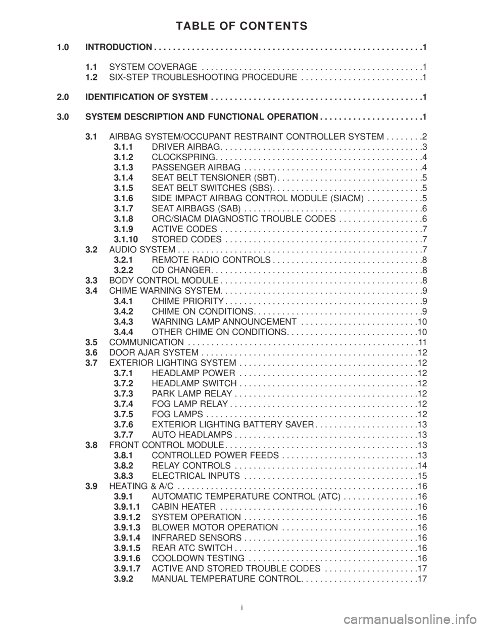
TABLE OF CONTENTS
1.0 INTRODUCTION.........................................................1
1.1SYSTEM COVERAGE...............................................1
1.2SIX-STEP TROUBLESHOOTING PROCEDURE..........................1
2.0 IDENTIFICATION OF SYSTEM.............................................1
3.0 SYSTEM DESCRIPTION AND FUNCTIONAL OPERATION......................1
3.1AIRBAG SYSTEM/OCCUPANT RESTRAINT CONTROLLER SYSTEM........2
3.1.1DRIVER AIRBAG...........................................3
3.1.2CLOCKSPRING............................................4
3.1.3PASSENGER AIRBAG......................................4
3.1.4SEAT BELT TENSIONER (SBT)...............................5
3.1.5SEAT BELT SWITCHES (SBS)................................5
3.1.6SIDE IMPACT AIRBAG CONTROL MODULE (SIACM)............5
3.1.7SEAT AIRBAGS (SAB)......................................6
3.1.8ORC/SIACM DIAGNOSTIC TROUBLE CODES..................6
3.1.9ACTIVE CODES...........................................7
3.1.10STORED CODES..........................................7
3.2AUDIO SYSTEM....................................................7
3.2.1REMOTE RADIO CONTROLS................................8
3.2.2CD CHANGER.............................................8
3.3BODY CONTROL MODULE...........................................8
3.4CHIME WARNING SYSTEM...........................................9
3.4.1CHIME PRIORITY..........................................9
3.4.2CHIME ON CONDITIONS....................................9
3.4.3WARNING LAMP ANNOUNCEMENT.........................10
3.4.4OTHER CHIME ON CONDITIONS............................10
3.5COMMUNICATION.................................................11
3.6DOOR AJAR SYSTEM..............................................12
3.7EXTERIOR LIGHTING SYSTEM......................................12
3.7.1HEADLAMP POWER......................................12
3.7.2HEADLAMP SWITCH......................................12
3.7.3PARK LAMP RELAY.......................................12
3.7.4FOG LAMP RELAY........................................12
3.7.5FOG LAMPS.............................................12
3.7.6EXTERIOR LIGHTING BATTERY SAVER......................13
3.7.7AUTO HEADLAMPS.......................................13
3.8FRONT CONTROL MODULE.........................................13
3.8.1CONTROLLED POWER FEEDS.............................13
3.8.2RELAY CONTROLS.......................................14
3.8.3ELECTRICAL INPUTS.....................................15
3.9HEATING & A/C...................................................16
3.9.1AUTOMATIC TEMPERATURE CONTROL (ATC)................16
3.9.1.1CABIN HEATER..........................................16
3.9.1.2SYSTEM OPERATION.....................................16
3.9.1.3BLOWER MOTOR OPERATION.............................16
3.9.1.4INFRARED SENSORS.....................................16
3.9.1.5REAR ATC SWITCH.......................................16
3.9.1.6COOLDOWN TESTING....................................16
3.9.1.7ACTIVE AND STORED TROUBLE CODES....................17
3.9.2MANUAL TEMPERATURE CONTROL.........................17
i
Page 22 of 4284
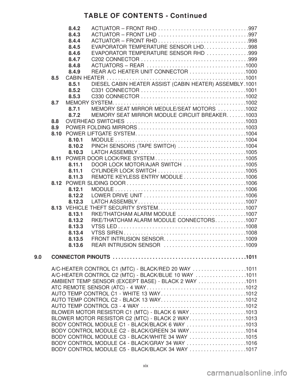
TABLE OF CONTENTS - Continued
8.4.2ACTUATOR ± FRONT RHD................................997
8.4.3ACTUATOR ± FRONT LHD................................997
8.4.4ACTUATOR ± FRONT RHD................................998
8.4.5EVAPORATOR TEMPERATURE SENSOR LHD................998
8.4.6EVAPORATOR TEMPERATURE SENSOR RHD...............999
8.4.7C202 CONNECTOR......................................999
8.4.8ACTUATORS ± REAR...................................1000
8.4.9REAR A/C HEATER UNIT CONNECTOR....................1000
8.5CABIN HEATER.................................................1001
8.5.1DIESEL CABIN HEATER ASSIST (CABIN HEATER) ASSEMBLY .1001
8.5.2C331 CONNECTOR.....................................1001
8.5.3C330 CONNECTOR.....................................1002
8.7MEMORY SYSTEM...............................................1002
8.7.1MEMORY SEAT MIRROR MEDULE/SEAT MOTORS..........1002
8.7.2MEMORY SEAT MIRROR MODULE CIRCUIT BREAKER.......1003
8.8OVERHEAD SWITCHES..........................................1003
8.9POWER FOLDING MIRRORS......................................1003
8.10POWER LIFTGATE SYSTEM.......................................1004
8.10.1MODULE..............................................1004
8.10.2PINCH SENSORS (TAPE SWITCH)........................1004
8.10.3LATCH ASSEMBLY......................................1005
8.11POWER DOOR LOCK/RKE SYSTEM................................1005
8.11.1DOOR LOCK MOTOR/AJAR SWITCH......................1005
8.11.1CYLINDER LOCK SWITCH...............................1005
8.11.3REMOTE KEYLESS ENTRY MODULE......................1006
8.12POWER SLIDING DOOR..........................................1006
8.12.1MODULE..............................................1006
8.12.2LOWER DRIVE UNIT....................................1006
8.12.3LATCH ASSEMBLY......................................1007
8.13VEHICLE THEFT SECURITY SYSTEM...............................1007
8.13.1RKE/THATCHAM ALARM MODULE........................1007
8.13.2RKE/THATCHAM ALARM MODULE CONNECTORS...........1007
8.13.3VTSS LED.............................................1008
8.13.4VTSS SIREN...........................................1008
8.13.5FRONT INTRUSION SENSOR.............................1009
8.13.6REAR INTRUSION SENSOR.............................1009
9.0 CONNECTOR PINOUTS...............................................1011
A/C-HEATER CONTROL C1 (MTC) - BLACK/RED 20 WAY...................1011
A/C-HEATER CONTROL C2 (MTC) - BLACK/BLUE 10 WAY..................1011
AMBIENT TEMP SENSOR (EXCEPT BASE) - BLACK 2 WAY.................1011
ATC REMOTE SENSOR (ATC)-4WAY...................................1012
AUTO TEMP CONTROL C1 - WHITE 13 WAY..............................1012
AUTO TEMP CONTROL C2 - BLACK 13 WAY..............................1012
AUTO TEMP CONTROL C3-4WAY.....................................1012
BLOWER MOTOR RESISTOR C1 (MTC) - BLACK 6 WAY....................1013
BLOWER MOTOR RESISTOR C2 (MTC) - BLACK 2 WAY....................1013
BODY CONTROL MODULE C1 - BLACK/BLACK 6 WAY.....................1013
BODY CONTROL MODULE C2 - BLACK/GREEN 34 WAY....................1014
BODY CONTROL MODULE C3 - BLACK/WHITE 34 WAY....................1015
BODY CONTROL MODULE C4 - BLACK/GRAY 34 WAY.....................1016
BODY CONTROL MODULE C5 - BLACK/BLACK 34 WAY....................1017
xix
Page 24 of 4284
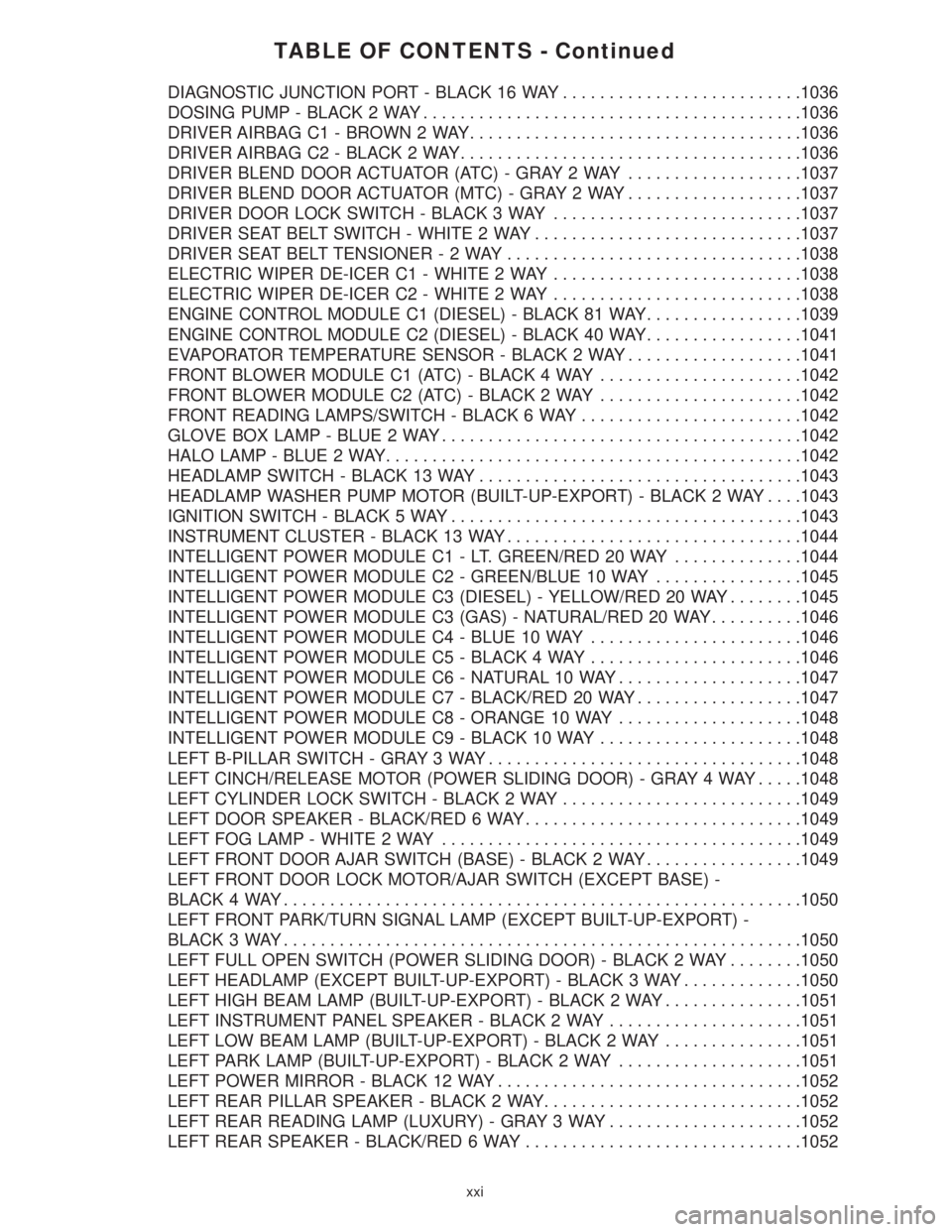
TABLE OF CONTENTS - Continued
DIAGNOSTIC JUNCTION PORT - BLACK 16 WAY..........................1036
DOSING PUMP - BLACK 2 WAY.........................................1036
DRIVER AIRBAG C1 - BROWN 2 WAY....................................1036
DRIVER AIRBAG C2 - BLACK 2 WAY.....................................1036
DRIVER BLEND DOOR ACTUATOR (ATC) - GRAY 2 WAY...................1037
DRIVER BLEND DOOR ACTUATOR (MTC) - GRAY 2 WAY...................1037
DRIVER DOOR LOCK SWITCH - BLACK 3 WAY...........................1037
DRIVER SEAT BELT SWITCH - WHITE 2 WAY.............................1037
DRIVER SEAT BELT TENSIONER-2WAY................................1038
ELECTRIC WIPER DE-ICER C1 - WHITE 2 WAY...........................1038
ELECTRIC WIPER DE-ICER C2 - WHITE 2 WAY...........................1038
ENGINE CONTROL MODULE C1 (DIESEL) - BLACK 81 WAY.................1039
ENGINE CONTROL MODULE C2 (DIESEL) - BLACK 40 WAY.................1041
EVAPORATOR TEMPERATURE SENSOR - BLACK 2 WAY...................1041
FRONT BLOWER MODULE C1 (ATC) - BLACK 4 WAY......................1042
FRONT BLOWER MODULE C2 (ATC) - BLACK 2 WAY......................1042
FRONT READING LAMPS/SWITCH - BLACK 6 WAY........................1042
GLOVE BOX LAMP - BLUE 2 WAY.......................................1042
HALO LAMP - BLUE 2 WAY.............................................1042
HEADLAMP SWITCH - BLACK 13 WAY...................................1043
HEADLAMP WASHER PUMP MOTOR (BUILT-UP-EXPORT) - BLACK 2 WAY. . . .1043
IGNITION SWITCH - BLACK 5 WAY......................................1043
INSTRUMENT CLUSTER - BLACK 13 WAY................................1044
INTELLIGENT POWER MODULE C1 - LT. GREEN/RED 20 WAY..............1044
INTELLIGENT POWER MODULE C2 - GREEN/BLUE 10 WAY................1045
INTELLIGENT POWER MODULE C3 (DIESEL) - YELLOW/RED 20 WAY........1045
INTELLIGENT POWER MODULE C3 (GAS) - NATURAL/RED 20 WAY..........1046
INTELLIGENT POWER MODULE C4 - BLUE 10 WAY.......................1046
INTELLIGENT POWER MODULE C5 - BLACK 4 WAY.......................1046
INTELLIGENT POWER MODULE C6 - NATURAL 10 WAY....................1047
INTELLIGENT POWER MODULE C7 - BLACK/RED 20 WAY..................1047
INTELLIGENT POWER MODULE C8 - ORANGE 10 WAY....................1048
INTELLIGENT POWER MODULE C9 - BLACK 10 WAY......................1048
LEFT B-PILLAR SWITCH - GRAY 3 WAY..................................1048
LEFT CINCH/RELEASE MOTOR (POWER SLIDING DOOR) - GRAY 4 WAY.....1048
LEFT CYLINDER LOCK SWITCH - BLACK 2 WAY..........................1049
LEFT DOOR SPEAKER - BLACK/RED 6 WAY..............................1049
LEFT FOG LAMP - WHITE 2 WAY.......................................1049
LEFT FRONT DOOR AJAR SWITCH (BASE) - BLACK 2 WAY.................1049
LEFT FRONT DOOR LOCK MOTOR/AJAR SWITCH (EXCEPT BASE) -
BLACK 4 WAY........................................................1050
LEFT FRONT PARK/TURN SIGNAL LAMP (EXCEPT BUILT-UP-EXPORT) -
BLACK 3 WAY........................................................1050
LEFT FULL OPEN SWITCH (POWER SLIDING DOOR) - BLACK 2 WAY........1050
LEFT HEADLAMP (EXCEPT BUILT-UP-EXPORT) - BLACK 3 WAY.............1050
LEFT HIGH BEAM LAMP (BUILT-UP-EXPORT) - BLACK 2 WAY...............1051
LEFT INSTRUMENT PANEL SPEAKER - BLACK 2 WAY.....................1051
LEFT LOW BEAM LAMP (BUILT-UP-EXPORT) - BLACK 2 WAY...............1051
LEFT PARK LAMP (BUILT-UP-EXPORT) - BLACK 2 WAY....................1051
LEFT POWER MIRROR - BLACK 12 WAY.................................1052
LEFT REAR PILLAR SPEAKER - BLACK 2 WAY............................1052
LEFT REAR READING LAMP (LUXURY) - GRAY 3 WAY.....................1052
LEFT REAR SPEAKER - BLACK/RED 6 WAY..............................1052
xxi
Page 26 of 4284
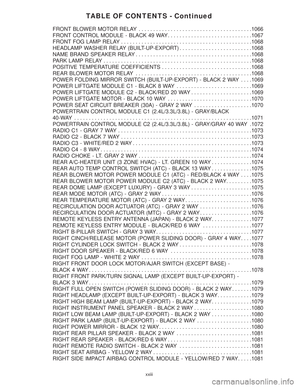
TABLE OF CONTENTS - Continued
FRONT BLOWER MOTOR RELAY.......................................1066
FRONT CONTROL MODULE - BLACK 49 WAY.............................1067
FRONT FOG LAMP RELAY.............................................1068
HEADLAMP WASHER RELAY (BUILT-UP-EXPORT).........................1068
NAME BRAND SPEAKER RELAY........................................1068
PARK LAMP RELAY...................................................1068
POSITIVE TEMPERATURE COEFFICIENTS...............................1068
REAR BLOWER MOTOR RELAY........................................1068
POWER FOLDING MIRROR SWITCH (BUILT-UP-EXPORT) - BLACK 2 WAY. . . .1069
POWER LIFTGATE MODULE C1 - BLACK 8 WAY..........................1069
POWER LIFTGATE MODULE C2 - BLACK/RED 20 WAY.....................1069
POWER LIFTGATE MOTOR - BLACK 10 WAY.............................1070
POWER SEAT CIRCUIT BREAKER (30A) - GRAY 2 WAY....................1070
POWERTRAIN CONTROL MODULE C1 (2.4L/3.3L/3.8L) - GRAY/BLACK
40-WAY.............................................................1071
POWERTRAIN CONTROL MODULE C2 (2.4L/3.3L/3.8L) - GRAY/GRAY 40 WAY .1072
RADIO C1 - GRAY 7 WAY..............................................1073
RADIO C2 - BLACK 7 WAY.............................................1073
RADIO C3 - WHITE/RED 2 WAY.........................................1073
RADIO C4-8WAY....................................................1074
RADIO CHOKE - LT. GRAY 2 WAY.......................................1074
REAR A/C-HEATER UNIT (3 ZONE HVAC) - LT. GREEN 10 WAY..............1074
REAR AUTO TEMP CONTROL SWITCH (ATC) - BLACK 13 WAY..............1075
REAR BLOWER MOTOR POWER MODULE C1 (ATC) - RED/BLACK 4 WAY. . . .1075
REAR BLOWER MOTOR POWER MODULE C2 (ATC) - BLACK 2 WAY.........1075
REAR DOME LAMP (EXCEPT LUXURY) - GRAY 3 WAY.....................1075
REAR MODE MOTOR (ATC) - GRAY 2 WAY...............................1076
REAR TEMPERATURE MOTOR (ATC) - GRAY 2 WAY.......................1076
RECIRCULATION DOOR ACTUATOR (ATC) - GRAY 2 WAY..................1076
RECIRCULATION DOOR ACTUATOR (MTC) - GRAY 2 WAY..................1076
REMOTE KEYLESS ENTRY ANTENNA (JAPAN) - BLACK 2 WAY..............1077
REMOTE KEYLESS ENTRY MODULE - BLACK/RED 6 WAY.................1077
RIGHT B-PILLAR SWITCH - GRAY 3 WAY.................................1077
RIGHT CINCH/RELEASE MOTOR (POWER SLIDING DOOR) - GRAY 4 WAY. . . .1077
RIGHT CYLINDER LOCK SWITCH - BLACK 2 WAY.........................1078
RIGHT DOOR SPEAKER - BLACK/RED 6 WAY............................1078
RIGHT FOG LAMP - WHITE 2 WAY......................................1078
RIGHT FRONT DOOR LOCK MOTOR/AJAR SWITCH (EXCEPT BASE) -
BLACK 4 WAY........................................................1078
RIGHT FRONT PARK/TURN SIGNAL LAMP (EXCEPT BUILT-UP-EXPORT) -
BLACK 3 WAY........................................................1079
RIGHT FULL OPEN SWITCH (POWER SLIDING DOOR) - BLACK 2 WAY.......1079
RIGHT HEADLAMP (EXCEPT BUILT-UP-EXPORT) - BLACK 3 WAY............1079
RIGHT HIGH BEAM LAMP (BUILT-UP-EXPORT) - BLACK 2 WAY..............1079
RIGHT INSTRUMENT PANEL SPEAKER - BLACK 2 WAY....................1080
RIGHT LOW BEAM LAMP (BUILT-UP-EXPORT) - BLACK 2 WAY..............1080
RIGHT PARK LAMP (BUILT-UP-EXPORT) - BLACK 2 WAY...................1080
RIGHT POWER MIRROR - BLACK 12 WAY................................1080
RIGHT REAR PILLAR SPEAKER - BLACK 2 WAY..........................1081
RIGHT REAR SPEAKER - BLACK/RED 6 WAY.............................1081
RIGHT REMOTE RADIO SWITCH - BLACK 2 WAY.........................1081
RIGHT SEAT AIRBAG - YELLOW 2 WAY..................................1081
RIGHT SIDE IMPACT AIRBAG CONTROL MODULE - YELLOW/RED 7 WAY.....1081
xxiii
Page 27 of 4284
TABLE OF CONTENTS - Continued
RIGHT SLIDING DOOR CONTROL MODULE C1 (POWER SLIDING DOOR) - BLACK
8 WAY ..............................................................1082
RIGHT SLIDING DOOR CONTROL MODULE C2 (POWER SLIDING DOOR) -
BLACK/RED 20 WAY..................................................1082
RIGHT SLIDING DOOR LATCH SENSING SWITCH (POWER SLIDING DOOR) -
BLACK 6 WAY........................................................1082
RIGHT SLIDING DOOR LOCK MOTOR (POWER SLIDING DOOR) - BLACK 4
WAY................................................................1083
RIGHT SLIDING DOOR LOCK MOTOR/AJAR SWITCH (MANUAL SLIDING DOOR) -
BLACK 4 WAY........................................................1083
RIGHT SLIDING DOOR MOTOR (POWER SLIDING DOOR) - BLACK 8 WAY. . . .1083
SENTRY KEY IMMOBILIZER MODULE - BLACK 6 WAY.....................1083
SIREN (UNITED KINGDOM) - BLACK 4 WAY..............................1083
THATCHAM ALARM MODULE C1 (UNITED KINGDOM) - BLACK 16 WAY.......1084
THATCHAM ALARM MODULE C2 (UNITED KINGDOM) - WHITE 4 WAY........1084
TRANSMISSION CONTROL MODULE (EATX) - BLACK 60 WAY..............1085
TXV SOLENOID (ATC)-2WAY.........................................1086
10.0 SCHEMATIC DIAGRAMS...............................................1087
10.1AIRBAG SYSTEM................................................1087
10.2AUDIO SYSTEM.................................................1088
10.2.1PREMIUM.............................................1088
10.2.2BASE.................................................1089
10.2.3CD CHANGER.........................................1090
10.2.4REMOTE RADIO CONTROLS.............................1091
10.3CABIN HEATER.................................................1092
10.4AUTOMATIC TEMPERATURE CONTROL SYSTEM....................1093
10.4.1FRONT ATC............................................1093
10.4.2REAR ATC.............................................1094
10.5COMMUNICATION...............................................1095
10.5.1PCM COMMUNICATION.................................1096
10.5.2ECM & CABIN HEATER ASSIST COMMUNICATION - DIESEL
ONLY.................................................1096
10.6DOOR AJAR WITH POWER SLIDING DOORS........................1097
10.7DOOR AJAR WITHOUT POWER SLIDING DOORS....................1098
10.8EXTERIOR LIGHTING............................................1099
10.9IGNITION SWITCH...............................................1100
10.10INSTRUMENT CLUSTER Ð BASE..................................1101
10.11INSTRUMENT CLUSTER & MESSAGE CENTER......................1102
10.12INTELLIGENT POWER MODULE/BODY CONTROL MODULE POWER AND
GROUNDS......................................................1103
10.13INTERIOR LIGHTING.............................................1104
10.14MANUAL TEMPERATURE CONTROLS..............................1105
10.14.1BASE MANUAL TEMPERATURE CONTROL SYSTEM LHD.....1105
10.14.2BASE MANUAL TEMPERATURE CONTROL SYSTEM RHD....1106
10.14.3DUAL-ZONE MANUAL TEMPERATURE CONTROL SYSTEM
LHD ..................................................1107
10.14.4DUAL-ZONE MANUAL TEMPERATURE CONTROL SYSTEM
RHD..................................................1108
10.14.5BLOWER MOTOR.......................................1109
10.15MEMORY SYSTEM...............................................1110
10.16OVERHEAD CONSOLE...........................................1111
xxiv
Page 42 of 4284
3.7.6 EXTERIOR LIGHTING BATTERY
SAVER
The BCM monitors the status of, and controls, the
Park Lamps, Headlamps and Fog Lamp relays. If
any exterior lamps are left ON after the ignition is
turned OFF, the BCM will turn them OFF after 3
minutes.
3.7.7 AUTO HEADLAMPS
This feature is available on vehicles equipped
with both the Electrocromatic Mirror (ECM) and
the Compass/Mini-Trip Computer (CMTC). When
the BCM detects a day/night signal from the CMTC,
an ECM is present and Auto Headlamp mode is
selected.
3.8 FRONT CONTROL MODULE
The Front Control Module (FCM) is an electrical
control and interface center located in the engine
compartment. When it is mated to the Power Dis-
tribution Center (PDC), it is referred to as the
Intelligent Power Module (IPM). The IPM, with its
fuses and relays provides power and signal distri-
bution throughout most of the vehicle. The FCM
receives both hard wire and digital electronic inputs
from the vehicle electrical system through the PDC.
Based on these inputs and the ignition switch
position, it provides direct power feeds and relay
control to some of the vehicles' most critical electri-
cal systems.
The Front Control Module provides the following
features:
Controlled power feeds:
²Front airbag system
²Side airbag system
²Headlamp power
²EATX module power (4 speed only)
²Front washer motor
²Rear washer motor
²Brake shift interlock system
Relay controls:
²Fog lamp relay (when equipped)
²Park lamp relay
²Front wiper on relay
²Front wiper high/low relay
²Accessory relay
²Horn relay
²Front & rear blower relay
²Name brand speakers (NBS) relay
²Electronic back light (EBL) run only relay
²Cabin heater relayElectrical inputs:
²Headlamp battery supplies1&2
²Module battery supply
²Power ground
²Ignition switch RUN or START position status
²Ignition switch START only status
²PCI Bus
²Stop lamp switch
²Horn switch
²Back-up switch
²Wiper park switch
²Washer fluid level switch
²Brake fluid level switch
²Ambient temperature sensor
²Right park lamp outage
²Left park lamp outage
²Battery IOD
²Battery (+) connection detection
²Flash reprogramming voltage
3.8.1 CONTROLLED POWER FEEDS
Front airbag system
The FCM provides power to the Occupant Re-
straint Control (ORC) system through two ªfuse-
lessº circuits (ORC RUN/START, and ORC RUN
only). These circuits are electronically controlled
and continuously monitored for malfunctions.
Power is supplied while the ignition switch is in the
RUN and START positions on pin 48 of the FCM
connector, and in the RUN only position on pin 29.
Side airbag system
The FCM provides power to the Side Impact
Airbag Control Module (SIACM) system through
one ªfuselessº circuit. This circuit is electronically
controlled and continuously monitored for malfunc-
tions. Power is supplied in the ignition RUN and
START positions on pin 28 of the FCM connector.
Headlamp power
The headlamp switch is a direct input to the
BCM. The BCM sends a PCI Bus message to the
FCM informing it of a headlamp switch status
change. The FCM then turns on power to the
headlamps through four ªfuselessº circuits. These
circuits are electronically controlled and continu-
ously monitored for malfunctions. Power is supplied
to each filament in a separate circuit (RH low on pin
6, RH high on pin 4, LH low on pin 3 and LH high
on pin 5). For vehicles equipped with Daytime
Running Lamps (DRL), the FCM electronically
steps down the headlamp voltage to provide the
desired illumination.
13
GENERAL INFORMATION
Page 43 of 4284
EATX power
The electronic automatic 4 speed transmission
module is powered when the ignition switch is in
the UNLOCK, RUN or START positions. This cir-
cuit is electronically controlled and continuously
monitored for malfunctions. Power is supplied
through pin 27 of the FCM connector.
Front washer motor
The front washer switch is a direct input to the
BCM. The BCM sends a PCI Bus message to the
FCM informing it of a request to wash. The front
washer motor is then powered through low side
control inside the FCM. This circuit is electronically
controlled and continuously monitored for malfunc-
tions. In addition, the FCM electronically protects
the washer motor from system voltages higher than
16 volts by automatically switching off the low side
circuit. The low side circuit is connected to pin 45 in
the FCM connector.
Rear washer motor
The rear washer switch is a direct input to the
BCM. The BCM sends a PCI Bus message to the
FCM informing it of a request to wash. The rear
washer motor is then powered through low side
control inside the FCM. This circuit is electronically
controlled and continuously monitored for malfunc-
tions. In addition, the FCM electronically protects
the washer motor from system voltages higher than
16 volts by automatically switching off the low side
circuit. The low side circuit is connected to pin 46 in
the FCM connector.
Brake shift interlock system
The brake shift interlock solenoid receives power
from both high side and low side controls inside the
FCM. The high side control is on the same circuit as
the EATX module power, and the low side control
comes through pin 47 of the FCM connector. The
solenoid is controlled by the low side driver when
the brake pedal is pressed. Both circuits are contin-
uously monitored for malfunctions.
3.8.2 RELAY CONTROLS
Fog lamp relay
The fog lamp switch is a direct input to the BCM.
The BCM sends a PCI Bus message to the FCM
informing it to turn on the fog lamp relay. The fog
lamp relay is then powered through low side control
on pin 33 of the FCM. This circuit is electronically
controlled and continuously monitored for malfunc-
tions. Fog lamp functionality is not equipped on all
vehicles. The FCM ªlearnsº that the vehicle is
equipped with fog lamps by reading the BCM PCI
Bus message.
Park lamp relay
The park lamp switch is a direct input to the
BCM. The BCM sends a PCI Bus message to the
FCM informing it to turn on the park lamp relay.
The park lamp relay is then powered through lowside control on pin 13 of the FCM. This circuit is
electronically controlled and continuously moni-
tored for malfunctions.
Front wiper on relay
The front wiper switch is a direct input to the
BCM. The BCM sends a PCI Bus message to the
FCM informing it to turn on the front wiper on
relay. The front wiper on relay is then powered
through low side control on pin 14 of the FCM. This
circuit is electronically controlled and continuously
monitored for malfunctions.
Front wiper high/low relay
The front wiper switch is a direct input to the
BCM. The BCM sends a PCI Bus message to the
FCM informing it to turn on the front wiper high/
low relay. The relay switches power between the low
speed and high speed windings of the wiper motor.
The front wiper high/low relay is powered through
low side control on pin 34 of the FCM. This circuit is
electronically controlled and continuously moni-
tored for malfunctions.
Accessory relay
The accessory relay works in conjunction with the
FCM's power accessory delay feature to control the
operation of the radio, power windows, washer
motors, wiper motors and power outlet. The acces-
sory relay is turned on through low side control on
pin 35 of the FCM. This circuit is electronically
controlled and continuously monitored for malfunc-
tions. Depending on the ignition switch position,
the accessory relay will remain on or will time-out
and turn off. The accessory relay remains on in the
RUN and ACCY positions of the ignition switch. In
the UNLK and OFF positions, the relay will remain
energized for 45 seconds then turn off. During this
time-out period, if the driver or passenger doors are
opened, the relay will turn off immediately. While
the ignition switch is in the START position, the
relay will also drop-out, then resume operation.
Accessory relay operation is most noticeable by
observing the operation of the radio or blower
functions.
Horn relay
The horn relay operates through a direct wire
input to the FCM from the horn switch (FCM pin
17) , or a PCI Bus message from the BCM. The relay
responds to the horn switch, remote door lock and
VTA alarm functions. The horn relay is powered
through low side control on pin 10 of the FCM.
Under normal operating conditions, if the horn is
pressed for longer than 30 seconds, the FCM will
automatically deactivate the horn to prevent dam-
age to it. The FCM will re-activate control of the
relay after a 25 second cool-down period. This
circuit is electronically controlled and continuously
monitored for malfunctions.
14
GENERAL INFORMATION
Page 44 of 4284
Front and rear blower relay
The blower control switch is part of the Automatic
Temperature Control (ATC) or A/C-Heater Control
Module, (Manual Temp). When the blower switch is
turned on, the ATC or A/C-Heater Control Module
sends a PCI Bus message to the FCM. The front and
rear blower relay is then powered through low side
control on pin 30 of the FCM. The relay provides the
high side to the blower motor, and the blower speed
is governed through low side control in the ATC or
A/C-Heater Control Module. This circuit is electron-
ically controlled and continuously monitored for
malfunctions.
Name Brand Speakers (NBS) relay
The NBS relay operates through the vehicle bus
interface between the radio and the FCM. When the
radio is turned on, the radio sends a PCI Bus
message to the FCM. The NBS relay is then pow-
ered on through low side control on pin 11 of the
FCM. The relay supplies power to the amplified
speaker, and ground is supplied through the radio.
This circuit is electronically controlled and contin-
uously monitored for malfunctions.
Electronic Back Light (EBL) relay
The rear defrost switch is part of the Automatic
Temperature Control or A/C-Heater Control Module
(Manual Temp). When the ignition switch is in the
RUN position and the rear defrost switch is turned
on, the ATC or A/C-Heater Control Module sends a
PCI Bus message to the FCM. The EBL run only
relay is then powered through low side control on
pin 31 of the FCM. The relay provides the high side
to the rear window defrost grid, and ground is
attached to the vehicle body. The FCM will only
allow the rear defrost to operate in the RUN posi-
tion. This circuit is electronically controlled and
continuously monitored for malfunctions.
Cabin Heater Relay
When the ignition is in Run, the FCM monitors
the PCI bus for the Cabin Heater Activation re-
quest. The A/C ± Heater Control Module initiates
this request only when all conditions for Cabin
Heater activation are favorable. The request carries
the status bit that the FCM requires to activate its
Cabin Heater Assist Control output. This output is
a low side driver (coming from FCM pin 15) which
supplies a ground signal to the Cabin Heater (pin
5). When the Cabin Heater receives this ground
signal input, it interprets this as an activation
signal. The FCM low side driver is also capable of
diagnostic sensing. The driver will sense an open
circuit when the driver is off, and will sense a short
to voltage when the driver is on. The FCM will set
DTCs for both of these types of faults. For addi-
tional information, refer to Cabin Heater under
General Information and Diagnostic Procedures in
the manual.3.8.3 ELECTRICAL INPUTS
Headlamp battery supplies1&2Ð12 volt
input on pins 1 and 2. Battery supply voltage for
switching headlamp circuits only.
Module battery supply Ð12 volt input on pin 9.
Battery supply voltage for all other FCM opera-
tions.
Power ground ÐGround source on pin 8 for all
FCM operations.
Ignition switch RUN or START position status
Ð12 volt input on pin 37. Allows the FCM to
determine the ignition switch status for related
FCM operations.
Ignition switch START only status Ð12 volt
input on pin 19. Allows the FCM to discriminate
between RUN/START input and START for related
FCM operations.
PCI Bus ÐApproximately 7.5 volt input on pin 22.
Allows the FCM to communicate with other mod-
ules on the vehicle bus.
Stop lamp Switch status Ð12 volt input on pin
44. Provides for brake shift interlock function.
Horn Switch ÐGround input on pin 17. Primary
means for engaging the horn.
Back-up switch ÐGround input on pin 39. Input
is converted to a PCI Bus status message for use by
other modules.
Wiper park switch ÐGround input on pin 16.
Used to determine park placement of wipers. Also
used as feedback to FCM to determine correct
operating mode of wipers.
Washer fluid level switch ÐGround input to
pull-up on pin 18. Ground is switched into the
circuit when washer bottle fluid level is low.
Brake fluid level switch ÐGround input to
pull-up on pin 36. Ground is switched into the
circuit when brake fluid level is low.
Ambient temperature sensor ÐResistive input
to pull-up on pin 25. Corresponding voltage level is
converted to a PCI Bus message for use by other
modules on the bus.
Right park lamp outage Ð12 volt input on pin
21. Used to determine if right park lamp circuit is
operating properly.
Left park lamp outage Ð12 volt input on pin 41.
Used to determine if left park lamp circuit is
operating properly.
Battery IOD Ð12 volt input on pin 20. The FCM
enters a low power consumption mode when the
ignition is turned OFF. This low current draw
battery supply keeps the microprocessor function-
ing in the low power mode.
Battery (+) connection detection Ð12 volt
input on pin 38. The battery connection on the PDC
incorporates the use of an internal switch to deter-
mine if the connector is properly mated and the
Connector Positive Assurance (CPA) is engaged. If
15
GENERAL INFORMATION
Page 45 of 4284
the CPA is not properly engaged, a voltage on pin 38
will be interpreted as an unseated connector and a
fault will set.
Flash programming voltage Ð20 volt input on
pin 42. When a DRBIIItis connected and the
proper flash reprogramming sequence is selected,
the 20 volt signal will be applied through pin 42.
3.9 HEATING & A/C
3.9.1 AUTOMATIC TEMPERATURE
CONTROL (ATC)
3.9.1.1 CABIN HEATER
For vehicles equipped with a diesel engine, a
Cabin Heater is used in conjunction with the HVAC
system. The Cabin Heater is designed to supply the
vehicle's occupants with heat prior to the engine
reaching operating temperature. For additional in-
formation on this system, refer to Cabin Heater
under General Information and Diagnostic Proce-
dures in this manual.
3.9.1.2 SYSTEM OPERATION
The Automatic Temperature Control (ATC) sys-
tem provides fully adjustable three zone climate
control; Driver front zone, Passenger Front zone
and Rear zone. The following is a list of ATC
controls and features:
± a POWER button which allows the operator to
turn the system completely off.
± AUTO HIGH/LOW switch allows the operator
to select what rate (fan speed) the system will
provide the selected comfort level.
± DRIVER, REAR and PASSENGER rocker
switches to select desired temperature for each
zone.
± Recirculation button allows cooling air to be
recirculated which maximizes cooling ability.
± A/C select button allows the operator to turn
the A/C compressor off.
± Defroster button allows the operator to turn on
the defroster independently during automatic
control.
± Fan control rotary switch for selecting fan
speed.
± Mode rotary switch for selecting heating/
cooling direction.
± REAR SYSTEM rotary switch for activating
the Rear ATC Switch allowing intermediate
passenger control over rear climate control.
3.9.1.3 BLOWER MOTOR OPERATION
The Automatic Temperature Control (ATC) front
and rear blower control provides continuously vari-
able control of air flow rate to meet occupant
comfort requirements. Pulse width modulation of
the blower motor power allows the front and rear
blower to operate at any speed from off to full speed.
When front or rear blower operation is required, the
ATC sends a PCI Bus message to the Front Control
Module (FCM) requesting blower relay ON. The
FCM provides a ground for the front and rear
blower motor relay coils, activating both relays. The
front and rear blower relays provide 12 volts to
their respective blower motor power modules. Each
module provides a 12 volt blower motor control
signal to the ATC. The ATC provides a pulse width
modulated (duty-cycle) ground signal to this circuit
based on climate requirements. The higher voltage
on the signal circuit (less duty-cycle ground) the
lower the blower speed request. The lower voltage
on the signal circuit (more duty-cycle ground) the
higher the blower speed request.
3.9.1.4 INFRARED SENSORS
The ATC system uses infrared (I/R) sensors to
monitor and control oocupant comfort levels. This
sensing system replaces interior air temperature
and solar sensors which required complex control
programs to maintain occupant comfort levels. The
front I/R sensor is located in the instrument panel
center bezel outlet. The rear I/R sensor is located in
the rear overhead mounted ATC switch.
3.9.1.5 REAR ATC SWITCH
The rear ATC switch is mounted in the headliner.
The switch contains a rotary adjustment for fan
speed, a rotary adjustment for mode selection, a
push button switch for temperature selection and a
digital display of the selected temperature.
3.9.1.6 COOLDOWN TESTING
The ATC provides a feature referred to as a
Cooldown Test. This test is initiated using the
DRBIIItand is designed to check the performance
of the air conditioning system. The ATC will not
perform this test if the ambient air temperature is
below 12ÉC (53ÉF). During the test, the ATC com-
pares the ambient air temperature to the evapora-
tor temperature sensor. To pass the cooldown test,
the evap temperature sensor must drop -6ÉC (20ÉF)
below ambient temperature within 2 minutes of
start of test. At the completion of the cooldown test
the DRBIIItwill display one of the following mes-
sages indicating test outcome:
± Cooldown Test Passed
± Cooldown Test Failed
16
GENERAL INFORMATION
Page 47 of 4284

3.9.2.8 HVAC SYSTEM RELAYS
The Integrated Power Module (IPM) houses and
provides power to the A/C Clutch Relay and Front
Blower Motor Relay.
3.9.2.9 EVAPORATOR TEMPERATURE
SENSOR
An evaporator temperature sensor, located on the
A/C expansion valve under the hood, replaces the
previously used fin sensor.
3.9.2.10 A/C ± HEATER CONTROL
MODULE, SWITCH OPERATION
Power Switch
The Power Switch is a momentary contact switch.
The switch LED illuminates when the switch is on.
The Power Switch setting is remembered during
power down.
Rear Window Defogger Switch
The Rear Window Defogger Switch is a momen-
tary contact switch. Toggling the switch results in
the A/C ± Heater Control Module sending a change
of state message to the FCM to provide rear window
defogger activation or deactivation respectively.
The switch LED illuminates when the switch is on.
Recirculation Switch
The Recirculation Switch is a momentary contact
switch. Toggling the switch on results in the A/C ±
Heater Control Module signaling the actuator to
close the fresh-air door. Toggling the switch off
results in the A/C ± Heater Control Module signal-
ing the actuator to open the fresh-air door. The
switch LED illuminates when the switch is on.
When the Power Switch is off, the A/C ± Heater
Control Module closes the fresh-air door to prevent
outside air from entering the passenger compart-
ment. The recirculation mode will cancel whenever
defrost is requested. Pressing the Recirculation
Switch while in defrost mode will illuminate the
Recirculation Switch LED, but only while the but-
ton is pressed. Under this circumstance, the recir-
culation request will be denied and the fresh-air
door will remain in the fresh position. All door
positions are determined relative to the number of
commutator pulses required to provide full travel of
the door. On command, the A/C ± Heater Control
Module runs the actuator for the number of pulses
corresponding to the desired door position.
A/C Switch
The A/C Switch is a momentary contact switch.
Toggling the switch results in the A/C ± Heater
Control Module sending a change of state message
to the Powertrain Control Module (PCM ± gasoline)or Engine Control Module (ECM ± diesel) to provide
A/C compressor clutch activation or deactivation
respectively. The A/C ± Heater Control Module will
only provide this request if EVAP function is found
acceptable. The Power Switch must be on to make
the A/C switch active. The switch LED illuminates
when the switch is on. The A/C Switch setting is
remembered during power down.
Blower Switch
The rotary Blower Switch has five positions, Low,
M1, M2, M3, and High. The Power Switch must be
on to make the Blower Switch active. Toggling the
Power Switch results in the A/C ± Heater Control
Module sending a request to the FCM to provide
blower motor activation or deactivation respec-
tively.
Blend Switch ± Single Zone
The single rotary Blend Switch has multiple
detents to control the full range of temperature that
the system can produce in any mode. Rotating the
switch results in the A/C ± Heater Control Module
signaling the actuator to move the blend door. All
door positions are determined relative to the num-
ber of commutator pulses required to provide full
travel of the door. On command, the A/C ± Heater
Control Module runs the actuator for the number of
pulses corresponding to the desired door position.
Blend Switch ± Dual Zone
The dual sliding Blend Switches have multiple
detents to control the full range of temperature that
the system can produce an any mode. The upper
slide pot controls the driver-side blend door, while
the lower slide pot controls the passenger-side
blend door. Sliding the switch results in the A/C ±
Heater Control Module signaling the actuator to
move the blend door. All door positions are deter-
mined relative to the number of commutator pulses
required to provide full travel of the door. On
command, the A/C ± Heater Control Module runs
the actuator for the number of pulses corresponding
to the desired door position.
Mode Switch
The single rotary Mode Switch has 13 detents to
either direct airflow to the panel outlets, a mix of
floor and panel outlets, floor outlets, a mix of floor
and defrost outlets, or defrost outlets. Rotating the
switch results in the A/C ± Heater Control Module
signaling the actuator to move the mode door. All
door positions are determined relative to the num-
ber of commutator pulses required to provide full
travel of the door. On command, the A/C ± Heater
Control Module runs the actuator for the number of
pulses corresponding to the desired door position.
18
GENERAL INFORMATION