hood open CHRYSLER VOYAGER 2001 Service Manual
[x] Cancel search | Manufacturer: CHRYSLER, Model Year: 2001, Model line: VOYAGER, Model: CHRYSLER VOYAGER 2001Pages: 4284, PDF Size: 83.53 MB
Page 14 of 4284
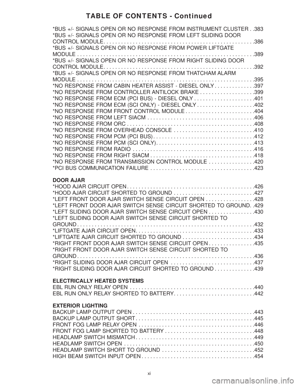
TABLE OF CONTENTS - Continued
*BUS +/- SIGNALS OPEN OR NO RESPONSE FROM INSTRUMENT CLUSTER . .383
*BUS +/- SIGNALS OPEN OR NO RESPONSE FROM LEFT SLIDING DOOR
CONTROL MODULE....................................................386
*BUS +/- SIGNALS OPEN OR NO RESPONSE FROM POWER LIFTGATE
MODULE.............................................................389
*BUS +/- SIGNALS OPEN OR NO RESPONSE FROM RIGHT SLIDING DOOR
CONTROL MODULE....................................................392
*BUS +/- SIGNALS OPEN OR NO RESPONSE FROM THATCHAM ALARM
MODULE.............................................................395
*NO RESPONSE FROM CABIN HEATER ASSIST - DIESEL ONLY..............397
*NO RESPONSE FROM CONTROLLER ANTILOCK BRAKE...................399
*NO RESPONSE FROM ECM (PCI BUS) - DIESEL ONLY.....................401
*NO RESPONSE FROM ECM (SCI ONLY) - DIESEL ONLY....................402
*NO RESPONSE FROM FRONT CONTROL MODULE........................404
*NO RESPONSE FROM LEFT SIACM.....................................406
*NO RESPONSE FROM ORC............................................408
*NO RESPONSE FROM OVERHEAD CONSOLE............................410
*NO RESPONSE FROM PCM (PCI BUS)...................................412
*NO RESPONSE FROM PCM (SCI ONLY)..................................413
*NO RESPONSE FROM RADIO..........................................416
*NO RESPONSE FROM RIGHT SIACM....................................418
*NO RESPONSE FROM TRANSMISSION CONTROL MODULE................420
*PCI BUS COMMUNICATION FAILURE....................................423
DOOR AJAR
*HOOD AJAR CIRCUIT OPEN............................................426
*HOOD AJAR CIRCUIT SHORTED TO GROUND............................427
*LEFT FRONT DOOR AJAR SWITCH SENSE CIRCUIT OPEN.................428
*LEFT FRONT DOOR AJAR SWITCH SENSE CIRCUIT SHORTED TO GROUND. .429
*LEFT SLIDING DOOR AJAR SWITCH SENSE CIRCUIT OPEN................430
*LEFT SLIDING DOOR AJAR SWITCH SENSE CIRCUIT SHORTED TO
GROUND.............................................................432
*LIFTGATE AJAR CIRCUIT OPEN.........................................433
*LIFTGATE AJAR CIRCUIT SHORTED TO GROUND.........................434
*RIGHT FRONT DOOR AJAR SWITCH SENSE CIRCUIT OPEN................435
*RIGHT FRONT DOOR AJAR SWITCH SENSE CIRCUIT SHORTED TO
GROUND.............................................................436
*RIGHT SLIDING DOOR AJAR CIRCUIT OPEN.............................437
*RIGHT SLIDING DOOR AJAR CIRCUIT SHORTED TO GROUND..............439
ELECTRICALLY HEATED SYSTEMS
EBL RUN ONLY RELAY OPEN...........................................440
EBL RUN ONLY RELAY SHORTED TO BATTERY............................442
EXTERIOR LIGHTING
BACKUP LAMP OUTPUT OPEN..........................................443
BACKUP LAMP OUTPUT SHORT.........................................445
FRONT FOG LAMP RELAY OPEN........................................446
FRONT FOG LAMP SHORTED TO BATTERY...............................448
HEADLAMP SWITCH MISMATCH.........................................449
HEADLAMP SWITCH OPEN.............................................450
HEADLAMP SWITCH SHORT TO GROUND................................452
HIGH BEAM SWITCH INPUT OPEN.......................................454
xi
Page 21 of 4284

TABLE OF CONTENTS - Continued
INTERNAL EEPROM WRITE ERROR......................................927
INTERNAL TRANSMIT FAILURE..........................................928
INTERNAL ULTRASONIC FAULT.........................................929
LOOPBACK ERROR....................................................935
NO VALID MESSAGES RECEIVED........................................936
PCI BUS SHORTED TO BATTERY........................................937
PCI BUS SHORTED TO GROUND........................................938
PCM MESSAGES NOT RECEIVED........................................939
VEHICLE THEFT ALARM INDICATOR OUTPUT OPEN.......................940
VEHICLE THEFT ALARM INDICATOR OUTPUT SHORT......................941
*ALARM TRIPS ON ITS OWN............................................942
*HOOD DOES NOT TRIP VTSS..........................................943
*LEFT FRONT DOOR DOES NOT TRIP VTSS..............................944
*LEFT SLIDING DOOR DOES NOT TRIP VTSS.............................945
*LIFTGATE DOES NOT TRIP VTSS.......................................946
*REPEATER LAMPS INOPERATIVE WITH ALARM...........................947
*RIGHT FRONT DOOR DOES NOT TRIP VTSS.............................948
*RIGHT SLIDING DOOR DOES NOT TRIP VTSS............................949
*VTSS INDICATOR INOPERATIVE........................................950
*VTSS INDICATOR LAMP INOPERATIVE...................................951
*VTSS SIREN INOP....................................................952
*VTSS WILL NOT ARM..................................................955
WINDSHIELD WIPER & WASHER
FR WIPER HI-LO RELAY OPEN..........................................956
FR WIPER HI-LO RELAY SHORT TO BATT.................................958
FRONT WASH SWITCH INPUT STUCK....................................959
FRONT WASHER OUTPUT OPEN........................................961
FRONT WIPER NOT PARKED............................................963
FRONT WIPER ON RELAY OPEN........................................965
FRONT WIPER ON RELAY SHORT TO BATT...............................966
FRONT WIPER PARK SWITCH SHORT TO GND............................967
FRONT WIPER SWITCH MUX INPUT OPEN................................969
FRONT WIPER SWITCH MUX INPUT SHORT TO GROUND...................971
HEADLAMP WASHER RELAY OPEN......................................973
HEADLAMP WASHER RELAY SHORT TO BATT.............................975
REAR WASH SWITCH INPUT STUCK.....................................976
REAR WASHER OUTPUT OPEN.........................................978
REAR WIPER OUTPUT OPEN...........................................980
REAR WIPER OUTPUT SHORT TO GROUND..............................982
REAR WIPER SWITCH MUX INPUT OPEN.................................984
REAR WIPER SWITCH MUX INPUT SHORT TO GROUND....................986
VERIFICATION TESTS
VERIFICATION TESTS..................................................988
8.0 COMPONENT LOCATIONS..............................................995
8.1AIRBAG SYSTEM.................................................995
8.2BODY CONTROL MODULE.........................................996
8.3ENGINE CONTROL MODULE.......................................996
8.4HEATING & A/C...................................................996
8.4.1ACTUATORS ± FRONT LHD...............................996
xviii
Page 34 of 4284
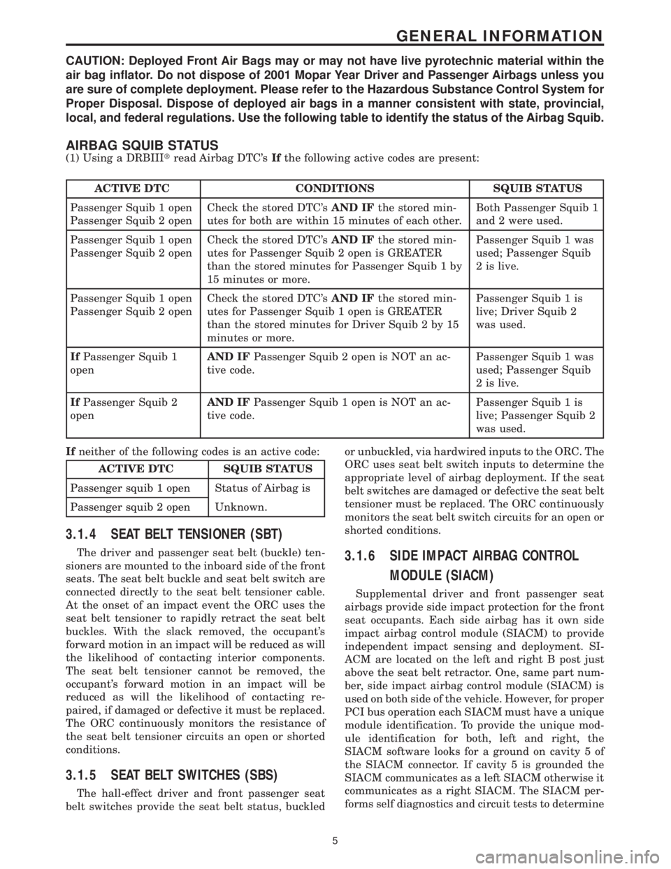
CAUTION: Deployed Front Air Bags may or may not have live pyrotechnic material within the
air bag inflator. Do not dispose of 2001 Mopar Year Driver and Passenger Airbags unless you
are sure of complete deployment. Please refer to the Hazardous Substance Control System for
Proper Disposal. Dispose of deployed air bags in a manner consistent with state, provincial,
local, and federal regulations. Use the following table to identify the status of the Airbag Squib.
AIRBAG SQUIB STATUS
(1) Using a DRBIIItread Airbag DTC'sIfthe following active codes are present:
ACTIVE DTC CONDITIONS SQUIB STATUS
Passenger Squib 1 open
Passenger Squib 2 openCheck the stored DTC'sAND IFthe stored min-
utes for both are within 15 minutes of each other.Both Passenger Squib 1
and 2 were used.
Passenger Squib 1 open
Passenger Squib 2 openCheck the stored DTC'sAND IFthe stored min-
utes for Passenger Squib 2 open is GREATER
than the stored minutes for Passenger Squib 1 by
15 minutes or more.Passenger Squib 1 was
used; Passenger Squib
2 is live.
Passenger Squib 1 open
Passenger Squib 2 openCheck the stored DTC'sAND IFthe stored min-
utes for Passenger Squib 1 open is GREATER
than the stored minutes for Driver Squib 2 by 15
minutes or more.Passenger Squib 1 is
live; Driver Squib 2
was used.
IfPassenger Squib 1
openAND IFPassenger Squib 2 open is NOT an ac-
tive code.Passenger Squib 1 was
used; Passenger Squib
2 is live.
IfPassenger Squib 2
openAND IFPassenger Squib 1 open is NOT an ac-
tive code.Passenger Squib 1 is
live; Passenger Squib 2
was used.
Ifneither of the following codes is an active code:
ACTIVE DTC SQUIB STATUS
Passenger squib 1 open Status of Airbag is
Passenger squib 2 open Unknown.
3.1.4 SEAT BELT TENSIONER (SBT)
The driver and passenger seat belt (buckle) ten-
sioners are mounted to the inboard side of the front
seats. The seat belt buckle and seat belt switch are
connected directly to the seat belt tensioner cable.
At the onset of an impact event the ORC uses the
seat belt tensioner to rapidly retract the seat belt
buckles. With the slack removed, the occupant's
forward motion in an impact will be reduced as will
the likelihood of contacting interior components.
The seat belt tensioner cannot be removed, the
occupant's forward motion in an impact will be
reduced as will the likelihood of contacting re-
paired, if damaged or defective it must be replaced.
The ORC continuously monitors the resistance of
the seat belt tensioner circuits an open or shorted
conditions.
3.1.5 SEAT BELT SWITCHES (SBS)
The hall-effect driver and front passenger seat
belt switches provide the seat belt status, buckledor unbuckled, via hardwired inputs to the ORC. The
ORC uses seat belt switch inputs to determine the
appropriate level of airbag deployment. If the seat
belt switches are damaged or defective the seat belt
tensioner must be replaced. The ORC continuously
monitors the seat belt switch circuits for an open or
shorted conditions.
3.1.6 SIDE IMPACT AIRBAG CONTROL
MODULE (SIACM)
Supplemental driver and front passenger seat
airbags provide side impact protection for the front
seat occupants. Each side airbag has it own side
impact airbag control module (SIACM) to provide
independent impact sensing and deployment. SI-
ACM are located on the left and right B post just
above the seat belt retractor. One, same part num-
ber, side impact airbag control module (SIACM) is
used on both side of the vehicle. However, for proper
PCI bus operation each SIACM must have a unique
module identification. To provide the unique mod-
ule identification for both, left and right, the
SIACM software looks for a ground on cavity 5 of
the SIACM connector. If cavity 5 is grounded the
SIACM communicates as a left SIACM otherwise it
communicates as a right SIACM. The SIACM per-
forms self diagnostics and circuit tests to determine
5
GENERAL INFORMATION
Page 47 of 4284

3.9.2.8 HVAC SYSTEM RELAYS
The Integrated Power Module (IPM) houses and
provides power to the A/C Clutch Relay and Front
Blower Motor Relay.
3.9.2.9 EVAPORATOR TEMPERATURE
SENSOR
An evaporator temperature sensor, located on the
A/C expansion valve under the hood, replaces the
previously used fin sensor.
3.9.2.10 A/C ± HEATER CONTROL
MODULE, SWITCH OPERATION
Power Switch
The Power Switch is a momentary contact switch.
The switch LED illuminates when the switch is on.
The Power Switch setting is remembered during
power down.
Rear Window Defogger Switch
The Rear Window Defogger Switch is a momen-
tary contact switch. Toggling the switch results in
the A/C ± Heater Control Module sending a change
of state message to the FCM to provide rear window
defogger activation or deactivation respectively.
The switch LED illuminates when the switch is on.
Recirculation Switch
The Recirculation Switch is a momentary contact
switch. Toggling the switch on results in the A/C ±
Heater Control Module signaling the actuator to
close the fresh-air door. Toggling the switch off
results in the A/C ± Heater Control Module signal-
ing the actuator to open the fresh-air door. The
switch LED illuminates when the switch is on.
When the Power Switch is off, the A/C ± Heater
Control Module closes the fresh-air door to prevent
outside air from entering the passenger compart-
ment. The recirculation mode will cancel whenever
defrost is requested. Pressing the Recirculation
Switch while in defrost mode will illuminate the
Recirculation Switch LED, but only while the but-
ton is pressed. Under this circumstance, the recir-
culation request will be denied and the fresh-air
door will remain in the fresh position. All door
positions are determined relative to the number of
commutator pulses required to provide full travel of
the door. On command, the A/C ± Heater Control
Module runs the actuator for the number of pulses
corresponding to the desired door position.
A/C Switch
The A/C Switch is a momentary contact switch.
Toggling the switch results in the A/C ± Heater
Control Module sending a change of state message
to the Powertrain Control Module (PCM ± gasoline)or Engine Control Module (ECM ± diesel) to provide
A/C compressor clutch activation or deactivation
respectively. The A/C ± Heater Control Module will
only provide this request if EVAP function is found
acceptable. The Power Switch must be on to make
the A/C switch active. The switch LED illuminates
when the switch is on. The A/C Switch setting is
remembered during power down.
Blower Switch
The rotary Blower Switch has five positions, Low,
M1, M2, M3, and High. The Power Switch must be
on to make the Blower Switch active. Toggling the
Power Switch results in the A/C ± Heater Control
Module sending a request to the FCM to provide
blower motor activation or deactivation respec-
tively.
Blend Switch ± Single Zone
The single rotary Blend Switch has multiple
detents to control the full range of temperature that
the system can produce in any mode. Rotating the
switch results in the A/C ± Heater Control Module
signaling the actuator to move the blend door. All
door positions are determined relative to the num-
ber of commutator pulses required to provide full
travel of the door. On command, the A/C ± Heater
Control Module runs the actuator for the number of
pulses corresponding to the desired door position.
Blend Switch ± Dual Zone
The dual sliding Blend Switches have multiple
detents to control the full range of temperature that
the system can produce an any mode. The upper
slide pot controls the driver-side blend door, while
the lower slide pot controls the passenger-side
blend door. Sliding the switch results in the A/C ±
Heater Control Module signaling the actuator to
move the blend door. All door positions are deter-
mined relative to the number of commutator pulses
required to provide full travel of the door. On
command, the A/C ± Heater Control Module runs
the actuator for the number of pulses corresponding
to the desired door position.
Mode Switch
The single rotary Mode Switch has 13 detents to
either direct airflow to the panel outlets, a mix of
floor and panel outlets, floor outlets, a mix of floor
and defrost outlets, or defrost outlets. Rotating the
switch results in the A/C ± Heater Control Module
signaling the actuator to move the mode door. All
door positions are determined relative to the num-
ber of commutator pulses required to provide full
travel of the door. On command, the A/C ± Heater
Control Module runs the actuator for the number of
pulses corresponding to the desired door position.
18
GENERAL INFORMATION
Page 55 of 4284
manual sliding door. When the child lock out switch
is on, the B pillar switches are disabled.
There is only one part number for the power
sliding door module (PSDM). The driver sliding
door harness has an additional ground circuit which
will identify it as the driver side. This eliminates
the need for a left and a right side module.
3.18.2 DIAGNOSTIC FEATURES
The PSDM can be flashed on vehicle via PCI bus
with a DRBIIItdiagnostic tool. The DRBIIItcan
read all inputs, actuate all outputs, read module
information, and read diagnostic trouble codes. As a
reminder, some DTC's can be set during normal
PSD operation.
3.18.3 SYSTEM INHIBITORS
1. Battery voltage too high or too low (above 16V,
below 9.5V)
2. Vehicle in gear
3. Vehicle speed > 0 mph/km/h
4. Child locks enabled inhibit the B pillar switch
operation
5. O/H console lockout will inhibit the B pillar
switches
6. Doors locked will inhibit all interior switches
from opening (Overhead Console, B Pillar). A
locked sliding door can be power closed.
3.19 REAR WINDOW DEFOG/HEATED
MIRROR/FRONT WIPER DE-ICE
The defroster button located on the HVAC control
controls the rear window defogger, heated side view
mirrors and front wiper de-icer grid. In addition the
front wiper de-ice function is turned on when front
defog/defrost mode is selected.
When the defroster button is pushed, the HVAC
control sends a bus message over the PCI bus to the
Front Control Module (FCM) which controls the
Rear Window Defogger relay. The defroster LED
will illuminate when the defroster function is on.
The defroster will function for 10 minutes or can be
cycled off sooner by pressing the defroster button
again. The front wiper de-icer grid receives its 12
volts from the accessory relay through fuse 11 and
the HVAC control module supplies the grid ground.
3.20 VEHICLE THEFT SECURITY SYSTEM
3.20.1 BASE ALARM SYSTEM
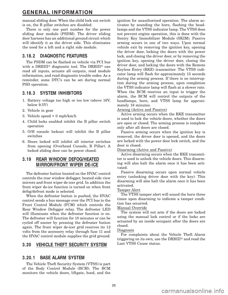
The Vehicle Theft Security System (VTSS) is part
of the Body Control Module (BCM). The BCM
monitors the vehicle doors, liftgate, hood, and theignition for unauthorized operation. The alarm ac-
tivates by sounding the horn, flashing the head-
lamps and the VTSS indicator lamp. The VTSS does
not prevent engine operation, this is done with the
Sentry Key Immobilizer Module (SKIM). Passive
arming occurs in one of two ways. Upon normal
vehicle exit by removing the ignition key, opening
the driver door, locking the doors with the power
lock, and closing the driver door, or by removing the
ignition key, opening the driver door, closing the
driver door, and locking the doors with the Remote
Keyless Entry (RKE) transmitter. The VTSS indi-
cator lamp will flash for approximately 15 seconds
during the arming process. If there is no interrup-
tion during the arming process, upon completion
the VTSS indicator lamp will flash at a slower rate.
When the BCM receives an input to trigger the
alarm, the BCM will control the outputs of the
headlamps, horn, and VTSS lamp for approxi-
mately 18 minutes.
Arming (Active and Passive)
Active arming occurs when the RKE transmitter
is used to lock the vehicle doors, whether the doors
are open or closed. The arming process is complete
only after all doors are closed.
Passive arming occurs when the ignition key is
removed, the driver door is opened, and the doors
are locked with the power door lock switch, and the
door is closed.
Disarming (Active and Passive)
Active disarming occurs when the RKE transmit-
ter is used to unlock the vehicle doors. This disarm-
ing will also halt the alarm once it has been acti-
vated.
Passive disarming occurs upon normal vehicle
entry (unlocking driver door with the key). This
disarming will also halt the alarm once it has been
activated.
Tamper Alert
The VTSS tamper alert will sound the horn three
times upon disarming to indicate a tamper condi-
tion has occurred.
Manual Override
The system will not arm if the doors are locked
using the manual lock control or if the locks are
actuated by an inside occupant after the doors are
closed.
Diagnosis
For complaints about the Vehicle Theft Alarm
triggering on its own, use the DRBIIItand read the
Last VTSS Cause status.
26
GENERAL INFORMATION
Page 56 of 4284

NOTE: A POWERTRAIN CONTROL MODULE
FROM A VEHICLE EQUIPPED WITH A
VEHICLE THEFT SECURITY SYSTEM
CANNOT BE USED IN A VEHICLE THAT IS
NOT EQUIPPED WITH A VEHICLE THEFT
SECURITY SYSTEM IF THE VTSS INDICATOR
LAMP COMES ON AFTER IGNITION ON AND
STAYS ON, THE PCI BUS COMMUNICATION
WITH THE POWERTRAIN CONTROL
MODULE HAS POSSIBLY BEEN LOST.
3.20.2 THATCHAM ALARM SYSTEM
The Thatcham Alarm Module monitors the vehi-
cle doors, liftgate, hood and the interior of the
vehicle for unauthorized operation. The vehicle
doors, liftgate, and hood use ajar switches as inputs
to the BCM to indicate their current status. The
interior of the vehicle is secured by the use of
Intrusion Sensors. The Intrusion Sensors are used
as inputs to the RKE/Thatcham Alarm Module to
report any motion in the interior of the vehicle. The
alarm activates by sounding the siren, flashing the
hazard lamps, and the VTSS Indicator Lamp.
Arming
Before arming, all doors, liftgate, and the hood
must be completely closed. The system can then be
armed by following a normal exit sequence, of
opening the door and then locking the doors with
the door lock switch and then closing the door. The
system can also be armed by opening the door,
closing the door and then locking the doors with the
RKE transmitter.
Disarming
To disarm the alarm system, the RKE transmit-
ter is used. The RKE transmitter will unlock the
vehicle doors and disarm the alarm system. The
RKE transmitter can also be used to halt the alarm
once it has been activated.
3.21 WIPER SYSTEM
3.21.1 FRONT WIPER
The front wiper/washer system consists of the
following features: lo-hi-speed, mist wipers, inter-
mittent wipers and wipe after wash. The front
wiper system is only active when the ignition switch
is in the RUN/ACC position. The vehicle operator
selects the front wiper function using the front
wiper switch (a resistive multiplexed stalk switch)
which is integral to the Multi-Function Switch. The
front wiper switch is hardwired to the Body Control
Module (BCM). Upon receiving a wiper switch sig-
nal, the BCM sends a PCI Bus message to the Front
Control Module (FCM). The FCM controls the ON/OFF relay, the HIGH/LOW relay and the front and
rear washer pump motors.
The Wiper system utilizes the BCM to control the
on/off and hi/low relays for the low and hi speed
wiper functions, intermittent wiper delay as the
switch position changes, pulse wipe, wipe after
wash mode and wiper motor functions. The BCM
uses the vehicle speed input to double the usual
delay time below 10 MPH (6 KPH).
3.21.2 SPEED SENSITIVE INTERMITTENT
WIPE MODE
There are 5 individual delay time settings with a
minimum delay of 1.7 seconds to a maximum of 18.4
seconds. When the vehicle speed is under 10 MPH
(6 KPM), the delay time is doubled, providing a
delay range of 3.4 seconds to 36.8 seconds.
3.21.3 PULSE WIPE
When the wiper is in the off position and the
driver presses the wash button for more than .062
seconds, but less than .5 seconds, 2 wipe cycles in
low speed mode will be provided.
3.21.4 PARK AFTER IGNITION OFF
Because the wiper relays are powered from the
battery, the BCM can run the wipers to park after
the ignition is turned off.
3.21.5 WIPE AFTER WASH
When the driver presses the wash button for over
.5 seconds and releases it, the wiper will continue to
run for 2 additional wipe cycles.
3.21.6 REAR WIPER
The rear wiper/washer system consists of the
following features: mist wipers, intermittent wipers
and wipe after wash. The rear wiper system is only
active when the ignition switch is in the RUN/ACC
position. The vehicle operator selects the rear wiper
function using one of the three buttons on the dash
mounted rear wiper switch. The rear wiper switch
is hardwired to the Body Control Module (BCM).
Upon receiving a wiper switch signal, the BCM
provides 12 volts to the rear wiper motor. Rear
washer occurs when the BCM receives a rear
washer switch ON input. The BCM sends a PCI Bus
message to the FCM requesting rear washer on.
The FCM activates the rear washer by providing a
ground for the rear washer motor.
3.21.7 SPEED SENSITIVE INTERMITTENT
WIPE MODE
The delay setting of the rear wiper system is
based solely on the vehicle speed. The delay time is
27
GENERAL INFORMATION
Page 455 of 4284
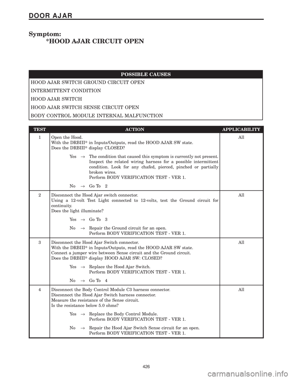
Symptom:
*HOOD AJAR CIRCUIT OPEN
POSSIBLE CAUSES
HOOD AJAR SWITCH GROUND CIRCUIT OPEN
INTERMITTENT CONDITION
HOOD AJAR SWITCH
HOOD AJAR SWITCH SENSE CIRCUIT OPEN
BODY CONTROL MODULE INTERNAL MALFUNCTION
TEST ACTION APPLICABILITY
1 Open the Hood.
With the DRBIIItin Inputs/Outputs, read the HOOD AJAR SW state.
Does the DRBIIItdisplay CLOSED?All
Ye s®The condition that caused this symptom is currently not present.
Inspect the related wiring harness for a possible intermittent
condition. Look for any chafed, pierced, pinched or partially
broken wires.
Perform BODY VERIFICATION TEST - VER 1.
No®Go To 2
2 Disconnect the Hood Ajar switch connector.
Using a 12-volt Test Light connected to 12-volts, test the Ground circuit for
continuity.
Does the light illuminate?All
Ye s®Go To 3
No®Repair the Ground circuit for an open.
Perform BODY VERIFICATION TEST - VER 1.
3 Disconnect the Hood Ajar Switch connector.
With the DRBIIItin Inputs/Outputs, read the HOOD AJAR SW state.
Connect a jumper wire between Sense circuit and the Ground circuit.
Does the DRBIIItdisplay HOOD AJAR SW: CLOSED?All
Ye s®Replace the Hood Ajar Switch.
Perform BODY VERIFICATION TEST - VER 1.
No®Go To 4
4 Disconnect the Body Control Module C3 harness connector.
Disconnect the Hood Ajar Switch harness connector.
Measure the resistance of the Sense circuit.
Is the resistance below 5.0 ohms?All
Ye s®Replace the Body Control Module.
Perform BODY VERIFICATION TEST - VER 1.
No®Repair the Hood Ajar Switch Sense circuit for an open.
Perform BODY VERIFICATION TEST - VER 1.
426
DOOR AJAR
Page 456 of 4284
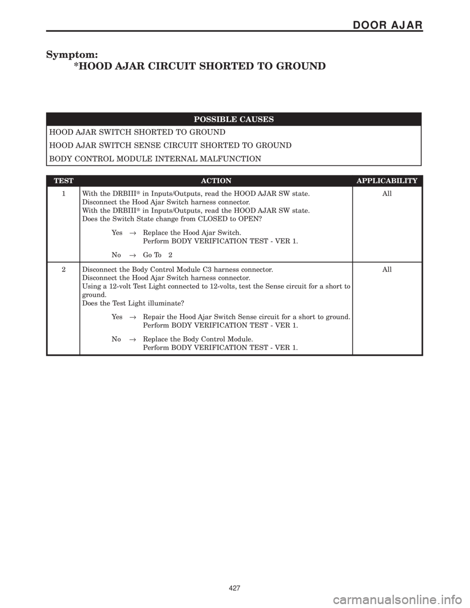
Symptom:
*HOOD AJAR CIRCUIT SHORTED TO GROUND
POSSIBLE CAUSES
HOOD AJAR SWITCH SHORTED TO GROUND
HOOD AJAR SWITCH SENSE CIRCUIT SHORTED TO GROUND
BODY CONTROL MODULE INTERNAL MALFUNCTION
TEST ACTION APPLICABILITY
1 With the DRBIIItin Inputs/Outputs, read the HOOD AJAR SW state.
Disconnect the Hood Ajar Switch harness connector.
With the DRBIIItin Inputs/Outputs, read the HOOD AJAR SW state.
Does the Switch State change from CLOSED to OPEN?All
Ye s®Replace the Hood Ajar Switch.
Perform BODY VERIFICATION TEST - VER 1.
No®Go To 2
2 Disconnect the Body Control Module C3 harness connector.
Disconnect the Hood Ajar Switch harness connector.
Using a 12-volt Test Light connected to 12-volts, test the Sense circuit for a short to
ground.
Does the Test Light illuminate?All
Ye s®Repair the Hood Ajar Switch Sense circuit for a short to ground.
Perform BODY VERIFICATION TEST - VER 1.
No®Replace the Body Control Module.
Perform BODY VERIFICATION TEST - VER 1.
427
DOOR AJAR
Page 972 of 4284
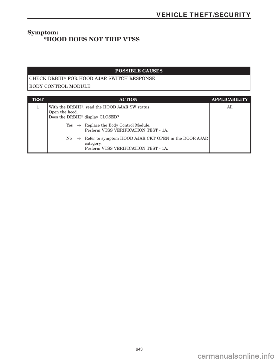
Symptom:
*HOOD DOES NOT TRIP VTSS
POSSIBLE CAUSES
CHECK DRBIIItFOR HOOD AJAR SWITCH RESPONSE
BODY CONTROL MODULE
TEST ACTION APPLICABILITY
1 With the DRBIIIt, read the HOOD AJAR SW status.
Open the hood.
Does the DRBIIItdisplay CLOSED?All
Ye s®Replace the Body Control Module.
Perform VTSS VERIFICATION TEST - 1A.
No®Refer to symptom HOOD AJAR CKT OPEN in the DOOR AJAR
category.
Perform VTSS VERIFICATION TEST - 1A.
943
VEHICLE THEFT/SECURITY
Page 1023 of 4284
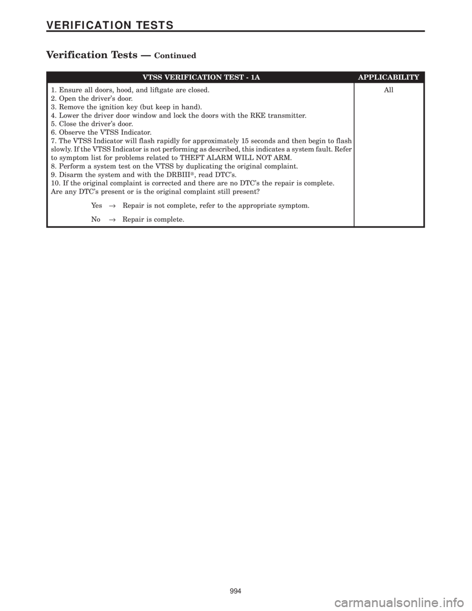
VTSS VERIFICATION TEST - 1A APPLICABILITY
1. Ensure all doors, hood, and liftgate are closed.
2. Open the driver's door.
3. Remove the ignition key (but keep in hand).
4. Lower the driver door window and lock the doors with the RKE transmitter.
5. Close the driver's door.
6. Observe the VTSS Indicator.
7. The VTSS Indicator will flash rapidly for approximately 15 seconds and then begin to flash
slowly. If the VTSS Indicator is not performing as described, this indicates a system fault. Refer
to symptom list for problems related to THEFT ALARM WILL NOT ARM.
8. Perform a system test on the VTSS by duplicating the original complaint.
9. Disarm the system and with the DRBIIIt, read DTC's.
10. If the original complaint is corrected and there are no DTC's the repair is complete.
Are any DTC's present or is the original complaint still present?All
Ye s®Repair is not complete, refer to the appropriate symptom.
No®Repair is complete.
994
VERIFICATION TESTS
Verification Tests ÐContinued