engine CHRYSLER VOYAGER 2002 Owners Manual
[x] Cancel search | Manufacturer: CHRYSLER, Model Year: 2002, Model line: VOYAGER, Model: CHRYSLER VOYAGER 2002Pages: 2399, PDF Size: 57.96 MB
Page 300 of 2399
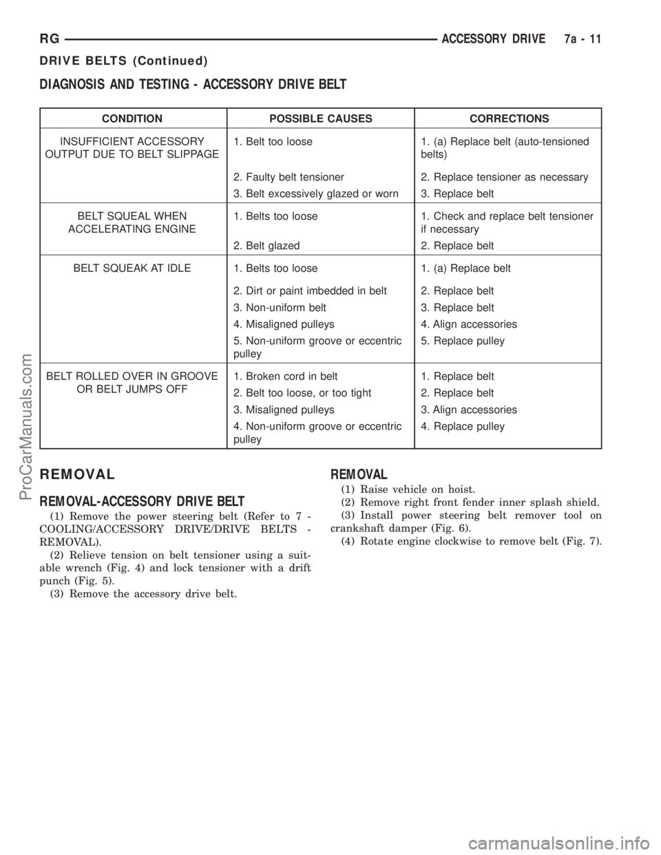
DIAGNOSIS AND TESTING - ACCESSORY DRIVE BELT
CONDITION POSSIBLE CAUSES CORRECTIONS
INSUFFICIENT ACCESSORY
OUTPUT DUE TO BELT SLIPPAGE1. Belt too loose 1. (a) Replace belt (auto-tensioned
belts)
2. Faulty belt tensioner 2. Replace tensioner as necessary
3. Belt excessively glazed or worn 3. Replace belt
BELT SQUEAL WHEN
ACCELERATING ENGINE1. Belts too loose 1. Check and replace belt tensioner
if necessary
2. Belt glazed 2. Replace belt
BELT SQUEAK AT IDLE 1. Belts too loose 1. (a) Replace belt
2. Dirt or paint imbedded in belt 2. Replace belt
3. Non-uniform belt 3. Replace belt
4. Misaligned pulleys 4. Align accessories
5. Non-uniform groove or eccentric
pulley5. Replace pulley
BELT ROLLED OVER IN GROOVE
OR BELT JUMPS OFF1. Broken cord in belt 1. Replace belt
2. Belt too loose, or too tight 2. Replace belt
3. Misaligned pulleys 3. Align accessories
4. Non-uniform groove or eccentric
pulley4. Replace pulley
REMOVAL
REMOVAL-ACCESSORY DRIVE BELT
(1) Remove the power steering belt (Refer to 7 -
COOLING/ACCESSORY DRIVE/DRIVE BELTS -
REMOVAL).
(2) Relieve tension on belt tensioner using a suit-
able wrench (Fig. 4) and lock tensioner with a drift
punch (Fig. 5).
(3) Remove the accessory drive belt.
REMOVAL
(1) Raise vehicle on hoist.
(2) Remove right front fender inner splash shield.
(3) Install power steering belt remover tool on
crankshaft damper (Fig. 6).
(4) Rotate engine clockwise to remove belt (Fig. 7).
RGACCESSORY DRIVE7a-11
DRIVE BELTS (Continued)
ProCarManuals.com
Page 303 of 2399
ENGINE
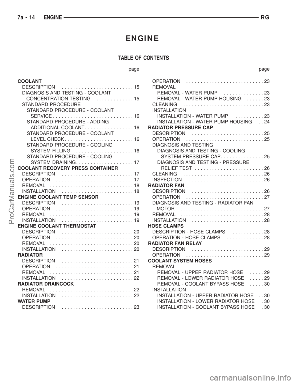
TABLE OF CONTENTS
page page
COOLANT
DESCRIPTION.........................15
DIAGNOSIS AND TESTING - COOLANT
CONCENTRATION TESTING.............15
STANDARD PROCEDURE
STANDARD PROCEDURE - COOLANT
SERVICE............................16
STANDARD PROCEDURE - ADDING
ADDITIONAL COOLANT.................16
STANDARD PROCEDURE - COOLANT
LEVEL CHECK........................16
STANDARD PROCEDURE - COOLING
SYSTEM FILLING.....................16
STANDARD PROCEDURE - COOLING
SYSTEM DRAINING....................17
COOLANT RECOVERY PRESS CONTAINER
DESCRIPTION.........................17
OPERATION...........................17
REMOVAL.............................18
INSTALLATION.........................18
ENGINE COOLANT TEMP SENSOR
DESCRIPTION.........................19
OPERATION...........................19
REMOVAL.............................19
INSTALLATION.........................19
ENGINE COOLANT THERMOSTAT
DESCRIPTION.........................20
OPERATION...........................20
REMOVAL.............................20
INSTALLATION.........................20
RADIATOR
DESCRIPTION.........................21
OPERATION...........................21
REMOVAL.............................21
INSTALLATION.........................22
RADIATOR DRAINCOCK
REMOVAL.............................22
INSTALLATION.........................22
WATER PUMP
DESCRIPTION.........................23OPERATION...........................23
REMOVAL
REMOVAL - WATER PUMP..............23
REMOVAL - WATER PUMP HOUSING......23
CLEANING............................23
INSTALLATION
INSTALLATION - WATER PUMP..........23
INSTALLATION - WATER PUMP HOUSING . . 24
RADIATOR PRESSURE CAP
DESCRIPTION.........................25
OPERATION...........................25
DIAGNOSIS AND TESTING
DIAGNOSIS AND TESTING - COOLING
SYSTEM PRESSURE CAP...............25
DIAGNOSIS AND TESTING - PRESSURE
RELIEF TEST........................26
CLEANING............................26
INSPECTION..........................26
RADIATOR FAN
DESCRIPTION.........................26
OPERATION...........................27
DIAGNOSIS AND TESTING - RADIATOR FAN
MOTOR .............................27
REMOVAL.............................28
INSTALLATION.........................28
HOSE CLAMPS
DESCRIPTION - HOSE CLAMPS...........28
OPERATION - HOSE CLAMPS.............28
RADIATOR FAN RELAY
DESCRIPTION.........................29
OPERATION...........................29
COOLANT SYSTEM HOSES
REMOVAL
REMOVAL - UPPER RADIATOR HOSE.....29
REMOVAL - LOWER RADIATOR HOSE.....29
REMOVAL - COOLANT BYPASS HOSE.....30
INSTALLATION
INSTALLATION - UPPER RADIATOR HOSE . . 30
INSTALLATION - LOWER RADIATOR HOSE . 30
INSTALLATION - COOLANT BYPASS HOSE . 30
7a - 14 ENGINERG
ProCarManuals.com
Page 304 of 2399
COOLANT
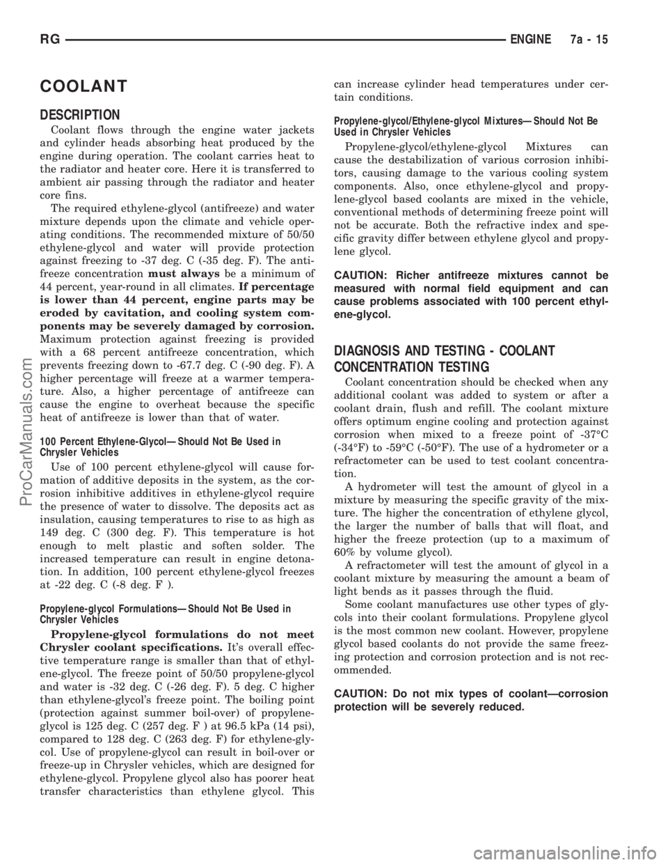
DESCRIPTION
Coolant flows through the engine water jackets
and cylinder heads absorbing heat produced by the
engine during operation. The coolant carries heat to
the radiator and heater core. Here it is transferred to
ambient air passing through the radiator and heater
core fins.
The required ethylene-glycol (antifreeze) and water
mixture depends upon the climate and vehicle oper-
ating conditions. The recommended mixture of 50/50
ethylene-glycol and water will provide protection
against freezing to -37 deg. C (-35 deg. F). The anti-
freeze concentrationmust alwaysbe a minimum of
44 percent, year-round in all climates.If percentage
is lower than 44 percent, engine parts may be
eroded by cavitation, and cooling system com-
ponents may be severely damaged by corrosion.
Maximum protection against freezing is provided
with a 68 percent antifreeze concentration, which
prevents freezing down to -67.7 deg. C (-90 deg. F). A
higher percentage will freeze at a warmer tempera-
ture. Also, a higher percentage of antifreeze can
cause the engine to overheat because the specific
heat of antifreeze is lower than that of water.
100 Percent Ethylene-GlycolÐShould Not Be Used in
Chrysler Vehicles
Use of 100 percent ethylene-glycol will cause for-
mation of additive deposits in the system, as the cor-
rosion inhibitive additives in ethylene-glycol require
the presence of water to dissolve. The deposits act as
insulation, causing temperatures to rise to as high as
149 deg. C (300 deg. F). This temperature is hot
enough to melt plastic and soften solder. The
increased temperature can result in engine detona-
tion. In addition, 100 percent ethylene-glycol freezes
at -22 deg. C (-8 deg. F ).
Propylene-glycol FormulationsÐShould Not Be Used in
Chrysler Vehicles
Propylene-glycol formulations do not meet
Chrysler coolant specifications.It's overall effec-
tive temperature range is smaller than that of ethyl-
ene-glycol. The freeze point of 50/50 propylene-glycol
and water is -32 deg. C (-26 deg. F). 5 deg. C higher
than ethylene-glycol's freeze point. The boiling point
(protection against summer boil-over) of propylene-
glycol is 125 deg. C (257 deg.F)at96.5 kPa (14 psi),
compared to 128 deg. C (263 deg. F) for ethylene-gly-
col. Use of propylene-glycol can result in boil-over or
freeze-up in Chrysler vehicles, which are designed for
ethylene-glycol. Propylene glycol also has poorer heat
transfer characteristics than ethylene glycol. Thiscan increase cylinder head temperatures under cer-
tain conditions.
Propylene-glycol/Ethylene-glycol MixturesÐShould Not Be
Used in Chrysler Vehicles
Propylene-glycol/ethylene-glycol Mixtures can
cause the destabilization of various corrosion inhibi-
tors, causing damage to the various cooling system
components. Also, once ethylene-glycol and propy-
lene-glycol based coolants are mixed in the vehicle,
conventional methods of determining freeze point will
not be accurate. Both the refractive index and spe-
cific gravity differ between ethylene glycol and propy-
lene glycol.
CAUTION: Richer antifreeze mixtures cannot be
measured with normal field equipment and can
cause problems associated with 100 percent ethyl-
ene-glycol.
DIAGNOSIS AND TESTING - COOLANT
CONCENTRATION TESTING
Coolant concentration should be checked when any
additional coolant was added to system or after a
coolant drain, flush and refill. The coolant mixture
offers optimum engine cooling and protection against
corrosion when mixed to a freeze point of -37ÉC
(-34ÉF) to -59ÉC (-50ÉF). The use of a hydrometer or a
refractometer can be used to test coolant concentra-
tion.
A hydrometer will test the amount of glycol in a
mixture by measuring the specific gravity of the mix-
ture. The higher the concentration of ethylene glycol,
the larger the number of balls that will float, and
higher the freeze protection (up to a maximum of
60% by volume glycol).
A refractometer will test the amount of glycol in a
coolant mixture by measuring the amount a beam of
light bends as it passes through the fluid.
Some coolant manufactures use other types of gly-
cols into their coolant formulations. Propylene glycol
is the most common new coolant. However, propylene
glycol based coolants do not provide the same freez-
ing protection and corrosion protection and is not rec-
ommended.
CAUTION: Do not mix types of coolantÐcorrosion
protection will be severely reduced.
RGENGINE7a-15
ProCarManuals.com
Page 305 of 2399
STANDARD PROCEDURE
STANDARD PROCEDURE - COOLANT SERVICE
For engine coolant recommended service schedule,
(Refer to LUBRICATION & MAINTENANCE/MAIN-
TENANCE SCHEDULES - DESCRIPTION).
STANDARD PROCEDURE - ADDING
ADDITIONAL COOLANT
The pressure/vent cap should not be removed
from the coolant recovery pressure container
when the engine is hot.When additional coolant is
needed to maintain this level, it should be added to
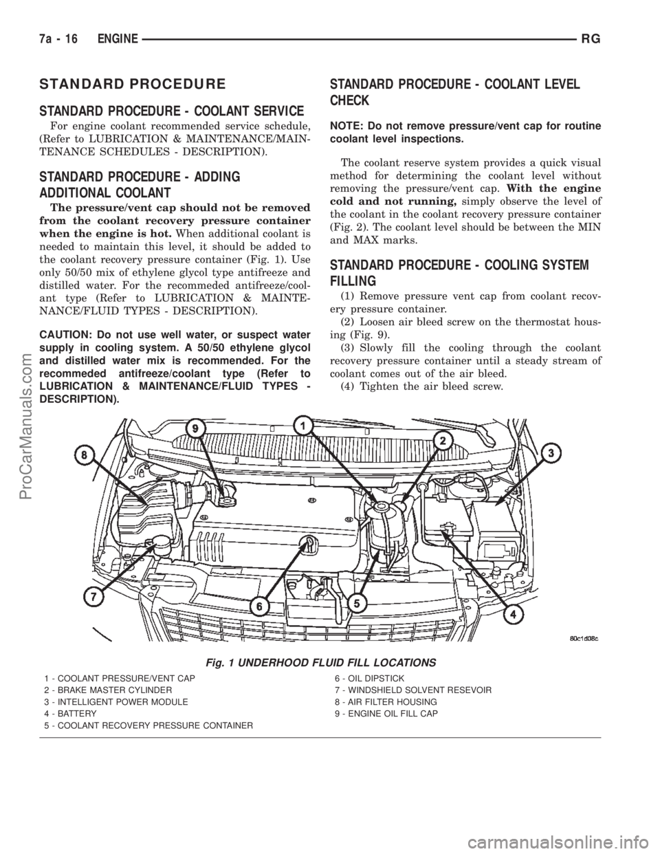
the coolant recovery pressure container (Fig. 1). Use
only 50/50 mix of ethylene glycol type antifreeze and
distilled water. For the recommeded antifreeze/cool-
ant type (Refer to LUBRICATION & MAINTE-
NANCE/FLUID TYPES - DESCRIPTION).
CAUTION: Do not use well water, or suspect water
supply in cooling system. A 50/50 ethylene glycol
and distilled water mix is recommended. For the
recommeded antifreeze/coolant type (Refer to
LUBRICATION & MAINTENANCE/FLUID TYPES -
DESCRIPTION).
STANDARD PROCEDURE - COOLANT LEVEL
CHECK
NOTE: Do not remove pressure/vent cap for routine
coolant level inspections.
The coolant reserve system provides a quick visual
method for determining the coolant level without
removing the pressure/vent cap.With the engine
cold and not running,simply observe the level of
the coolant in the coolant recovery pressure container
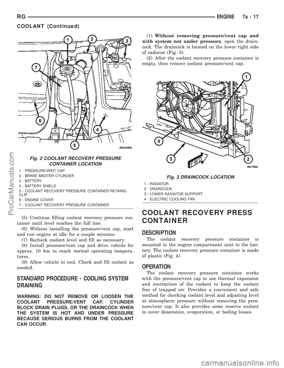
(Fig. 2). The coolant level should be between the MIN
and MAX marks.
STANDARD PROCEDURE - COOLING SYSTEM
FILLING
(1) Remove pressure vent cap from coolant recov-
ery pressure container.
(2) Loosen air bleed screw on the thermostat hous-
ing (Fig. 9).
(3) Slowly fill the cooling through the coolant
recovery pressure container until a steady stream of
coolant comes out of the air bleed.
(4) Tighten the air bleed screw.
Fig. 1 UNDERHOOD FLUID FILL LOCATIONS
1 - COOLANT PRESSURE/VENT CAP
2 - BRAKE MASTER CYLINDER
3 - INTELLIGENT POWER MODULE
4 - BATTERY
5 - COOLANT RECOVERY PRESSURE CONTAINER6 - OIL DIPSTICK
7 - WINDSHIELD SOLVENT RESEVOIR
8 - AIR FILTER HOUSING
9 - ENGINE OIL FILL CAP
7a - 16 ENGINERG
ProCarManuals.com
Page 306 of 2399
(5) Continue filling coolant recovery pressure con-
tainer until level reaches the full line.
(6) Without installing the pressure/vent cap, start
and run engine at idle for a couple minutes.
(7) Recheck coolant level and fill as necessary.
(8) Install pressure/vent cap and drive vehicle for
approx. 10 km to reach normal operating tempera-
tures.
(9) Allow vehicle to cool. Check and fill coolant as
needed.
STANDARD PROCEDURE - COOLING SYSTEM
DRAINING
WARNING: DO NOT REMOVE OR LOOSEN THE
COOLANT PRESSURE/VENT CAP, CYLINDER
BLOCK DRAIN PLUGS, OR THE DRAINCOCK WHEN
THE SYSTEM IS HOT AND UNDER PRESSURE
BECAUSE SERIOUS BURNS FROM THE COOLANT
CAN OCCUR.(1)Without removing pressure/vent cap and
with system not under pressure, open the drain-
cock. The draincock is located on the lower right side
of radiator (Fig. 3).
(2) After the coolant recovery pressure container is
empty, then remove coolant pressure/vent cap.
COOLANT RECOVERY PRESS
CONTAINER
DESCRIPTION
The coolant recovery pressure container is
mounted in the engine compartment next to the bat-
tery. The coolant recovery pressure container is made
of plastic (Fig. 4).
OPERATION
The coolant recovery pressure container works
with the pressure/vent cap to use thermal expansion
and contraction of the coolant to keep the coolant
free of trapped air. Provides a convenient and safe
method for checking coolant level and adjusting level
at atmospheric pressure without removing the pres-
sure/vent cap. It also provides some reserve coolant
to cover deaeration, evaporation, or boiling losses.
Fig. 2 COOLANT RECOVERY PRESSURE
CONTAINER LOCATION
1 - PRESSURE/VENT CAP
2 - BRAKE MASTER CYLINDER
3 - BATTERY
4 - BATTERY SHIELD
5 - COOLANT RECOVERY PRESSURE CONTAINER RETAING
CLIP
6 - ENGINE COVER
7 - COOLANT RECOVERY PRESSURE CONTAINER
Fig. 3 DRAINCOCK LOCATION
1 - RADIATOR
2 - DRAINCOCK
3 - LOWER RADIATOR SUPPORT
4 - ELECTRIC COOLING FAN
RGENGINE7a-17
COOLANT (Continued)
ProCarManuals.com
Page 307 of 2399
REMOVAL
(1) Drain cooling system below level of coolant
recovery pressure bottle. (Refer to 7 - COOLING/EN-
GINE/COOLANT - STANDARD PROCEDURE)
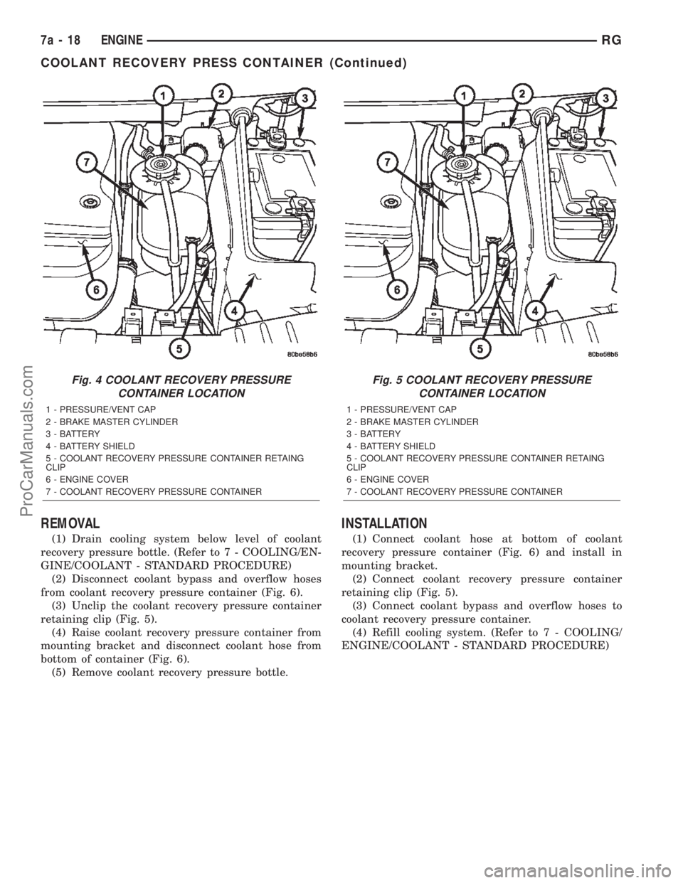
(2) Disconnect coolant bypass and overflow hoses
from coolant recovery pressure container (Fig. 6).
(3) Unclip the coolant recovery pressure container
retaining clip (Fig. 5).
(4) Raise coolant recovery pressure container from
mounting bracket and disconnect coolant hose from
bottom of container (Fig. 6).
(5) Remove coolant recovery pressure bottle.
INSTALLATION
(1) Connect coolant hose at bottom of coolant
recovery pressure container (Fig. 6) and install in
mounting bracket.
(2) Connect coolant recovery pressure container
retaining clip (Fig. 5).
(3) Connect coolant bypass and overflow hoses to
coolant recovery pressure container.
(4) Refill cooling system. (Refer to 7 - COOLING/
ENGINE/COOLANT - STANDARD PROCEDURE)
Fig. 4 COOLANT RECOVERY PRESSURE
CONTAINER LOCATION
1 - PRESSURE/VENT CAP
2 - BRAKE MASTER CYLINDER
3 - BATTERY
4 - BATTERY SHIELD
5 - COOLANT RECOVERY PRESSURE CONTAINER RETAING
CLIP
6 - ENGINE COVER
7 - COOLANT RECOVERY PRESSURE CONTAINER
Fig. 5 COOLANT RECOVERY PRESSURE
CONTAINER LOCATION
1 - PRESSURE/VENT CAP
2 - BRAKE MASTER CYLINDER
3 - BATTERY
4 - BATTERY SHIELD
5 - COOLANT RECOVERY PRESSURE CONTAINER RETAING
CLIP
6 - ENGINE COVER
7 - COOLANT RECOVERY PRESSURE CONTAINER
7a - 18 ENGINERG
COOLANT RECOVERY PRESS CONTAINER (Continued)
ProCarManuals.com
Page 308 of 2399
ENGINE COOLANT TEMP
SENSOR
DESCRIPTION
The engine coolant temperature sensor threads
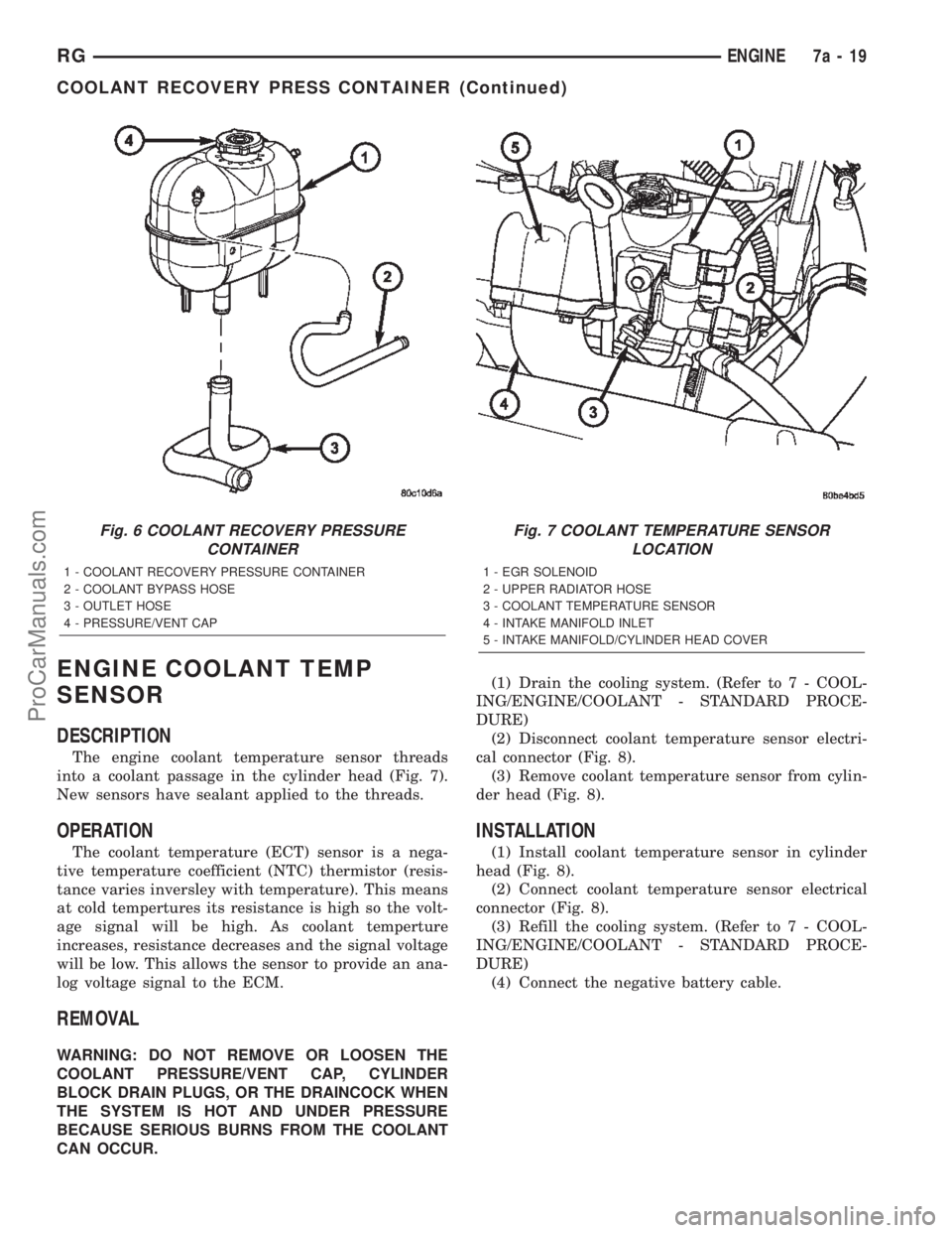
into a coolant passage in the cylinder head (Fig. 7).
New sensors have sealant applied to the threads.
OPERATION
The coolant temperature (ECT) sensor is a nega-
tive temperature coefficient (NTC) thermistor (resis-
tance varies inversley with temperature). This means
at cold tempertures its resistance is high so the volt-
age signal will be high. As coolant temperture
increases, resistance decreases and the signal voltage
will be low. This allows the sensor to provide an ana-
log voltage signal to the ECM.
REMOVAL
WARNING: DO NOT REMOVE OR LOOSEN THE
COOLANT PRESSURE/VENT CAP, CYLINDER
BLOCK DRAIN PLUGS, OR THE DRAINCOCK WHEN
THE SYSTEM IS HOT AND UNDER PRESSURE
BECAUSE SERIOUS BURNS FROM THE COOLANT
CAN OCCUR.(1) Drain the cooling system. (Refer to 7 - COOL-
ING/ENGINE/COOLANT - STANDARD PROCE-
DURE)
(2) Disconnect coolant temperature sensor electri-
cal connector (Fig. 8).
(3) Remove coolant temperature sensor from cylin-
der head (Fig. 8).
INSTALLATION
(1) Install coolant temperature sensor in cylinder
head (Fig. 8).
(2) Connect coolant temperature sensor electrical
connector (Fig. 8).
(3) Refill the cooling system. (Refer to 7 - COOL-
ING/ENGINE/COOLANT - STANDARD PROCE-
DURE)
(4) Connect the negative battery cable.
Fig. 6 COOLANT RECOVERY PRESSURE
CONTAINER
1 - COOLANT RECOVERY PRESSURE CONTAINER
2 - COOLANT BYPASS HOSE
3 - OUTLET HOSE
4 - PRESSURE/VENT CAP
Fig. 7 COOLANT TEMPERATURE SENSOR
LOCATION
1 - EGR SOLENOID
2 - UPPER RADIATOR HOSE
3 - COOLANT TEMPERATURE SENSOR
4 - INTAKE MANIFOLD INLET
5 - INTAKE MANIFOLD/CYLINDER HEAD COVER
RGENGINE7a-19
COOLANT RECOVERY PRESS CONTAINER (Continued)
ProCarManuals.com
Page 309 of 2399
ENGINE COOLANT
THERMOSTAT
DESCRIPTION
A pellet-type thermostat controls the operating
temperature of the engine by controlling the amount
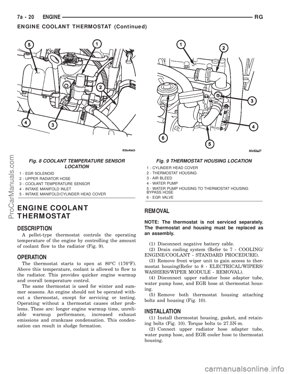
of coolant flow to the radiator (Fig. 9).
OPERATION
The thermostat starts to open at 80ÉC (176ÉF).
Above this temperature, coolant is allowed to flow to
the radiator. This provides quicker engine warmup
and overall temperature control.
The same thermostat is used for winter and sum-
mer seasons. An engine should not be operated with-
out a thermostat, except for servicing or testing.
Operating without a thermostat causes other prob-
lems. These are: longer engine warmup time, unreli-
able warmup performance, increased exhaust
emissions and crankcase condensation. This conden-
sation can result in sludge formation.
REMOVAL
NOTE: The thermostat is not serviced separately.
The thermostat and housing must be replaced as
an assembly.
(1) Disconnect negative battery cable.
(2) Drain cooling system (Refer to 7 - COOLING/
ENGINE/COOLANT - STANDARD PROCEDURE).
(3) Remove front wiper unit to gain access to ther-
mostat housing(Refer to 8 - ELECTRICAL/WIPERS/
WASHERS/WIPER MODULE - REMOVAL).
(4) Disconnect upper radiator hose adapter tube,
water pump hose, and EGR hose at thermostat hous-
ing.
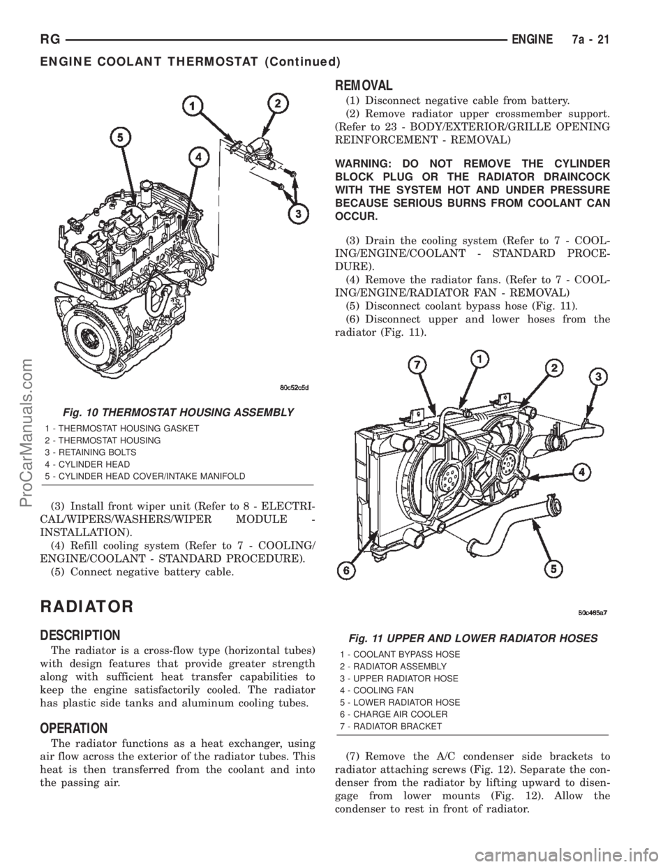
(5) Remove both thermostat housing attaching
bolts and housing (Fig. 10).
INSTALLATION
(1) Install thermostat housing, gasket, and retain-
ing bolts (Fig. 10). Torque bolts to 27.5N´m.
(2) Connect upper radiator hose adapter tube,
water pump hose, and EGR cooler hose to thermostat
housing.
Fig. 8 COOLANT TEMPERATURE SENSOR
LOCATION
1 - EGR SOLENOID
2 - UPPER RADIATOR HOSE
3 - COOLANT TEMPERATURE SENSOR
4 - INTAKE MANIFOLD INLET
5 - INTAKE MANIFOLD/CYLINDER HEAD COVER
Fig. 9 THERMOSTAT HOUSING LOCATION
1 - CYLINDER HEAD COVER
2 - THERMOSTAT HOUSING
3 - AIR BLEED
4 - WATER PUMP
5 - WATER PUMP HOUSING TO THERMOSTAT HOUSING
BYPASS HOSE
6 - E G R VA LV E
7a - 20 ENGINERG
ENGINE COOLANT THERMOSTAT (Continued)
ProCarManuals.com
Page 310 of 2399
(3) Install front wiper unit (Refer to 8 - ELECTRI-
CAL/WIPERS/WASHERS/WIPER MODULE -
INSTALLATION).
(4) Refill cooling system (Refer to 7 - COOLING/
ENGINE/COOLANT - STANDARD PROCEDURE).
(5) Connect negative battery cable.
RADIATOR
DESCRIPTION
The radiator is a cross-flow type (horizontal tubes)
with design features that provide greater strength
along with sufficient heat transfer capabilities to
keep the engine satisfactorily cooled. The radiator
has plastic side tanks and aluminum cooling tubes.
OPERATION
The radiator functions as a heat exchanger, using
air flow across the exterior of the radiator tubes. This
heat is then transferred from the coolant and into
the passing air.
REMOVAL
(1) Disconnect negative cable from battery.
(2) Remove radiator upper crossmember support.
(Refer to 23 - BODY/EXTERIOR/GRILLE OPENING
REINFORCEMENT - REMOVAL)
WARNING: DO NOT REMOVE THE CYLINDER
BLOCK PLUG OR THE RADIATOR DRAINCOCK
WITH THE SYSTEM HOT AND UNDER PRESSURE
BECAUSE SERIOUS BURNS FROM COOLANT CAN
OCCUR.
(3) Drain the cooling system (Refer to 7 - COOL-
ING/ENGINE/COOLANT - STANDARD PROCE-
DURE).
(4) Remove the radiator fans. (Refer to 7 - COOL-
ING/ENGINE/RADIATOR FAN - REMOVAL)
(5) Disconnect coolant bypass hose (Fig. 11).
(6) Disconnect upper and lower hoses from the
radiator (Fig. 11).
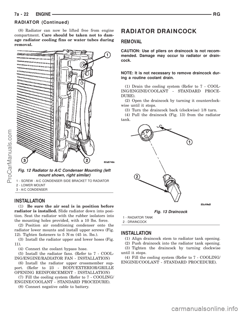
(7) Remove the A/C condenser side brackets to
radiator attaching screws (Fig. 12). Separate the con-
denser from the radiator by lifting upward to disen-
gage from lower mounts (Fig. 12). Allow the
condenser to rest in front of radiator.
Fig. 10 THERMOSTAT HOUSING ASSEMBLY
1 - THERMOSTAT HOUSING GASKET
2 - THERMOSTAT HOUSING
3 - RETAINING BOLTS
4 - CYLINDER HEAD
5 - CYLINDER HEAD COVER/INTAKE MANIFOLD
Fig. 11 UPPER AND LOWER RADIATOR HOSES
1 - COOLANT BYPASS HOSE
2 - RADIATOR ASSEMBLY
3 - UPPER RADIATOR HOSE
4 - COOLING FAN
5 - LOWER RADIATOR HOSE
6 - CHARGE AIR COOLER
7 - RADIATOR BRACKET
RGENGINE7a-21
ENGINE COOLANT THERMOSTAT (Continued)
ProCarManuals.com
Page 311 of 2399
(8) Radiator can now be lifted free from engine
compartment.Care should be taken not to dam-
age radiator cooling fins or water tubes during
removal.
INSTALLATION
(1)Be sure the air seal is in position before
radiator is installed.Slide radiator down into posi-
tion. Seat the radiator with the rubber isolators into
the mounting holes provided, with a 10 lbs. force.
(2) Position air conditioning condenser onto the
radiator lower mounts and install upper screws (Fig.
12). Tighten fasteners to 5 N´m (45 in. lbs.).
(3) Install the radiator upper and lower hoses (Fig.
11).
(4) Connect the coolant bypass hose.
(5) Install the radiator fans. (Refer to 7 - COOL-
ING/ENGINE/RADIATOR FAN - INSTALLATION)
(6) Install the radiator upper crossmember sup-
port. (Refer to 23 - BODY/EXTERIOR/GRILLE
OPENING REINFORCEMENT - INSTALLATION)
(7) Fill the cooling system (Refer to 7 - COOLING/
ENGINE/COOLANT - STANDARD PROCEDURE).
(8) Connect negative cable to battery.
RADIATOR DRAINCOCK
REMOVAL
CAUTION: Use of pliers on draincock is not recom-
mended. Damage may occur to radiator or drain-
cock.
NOTE: It is not necessary to remove draincock dur-
ing a routine coolant drain.
(1) Drain the cooling system (Refer to 7 - COOL-
ING/ENGINE/COOLANT - STANDARD PROCE-
DURE).
(2) Open the draincock by turning it counterclock-
wise until it stops.
(3) Turn the draincock back (clockwise) 1/8 turn.
(4) Pull the draincock (Fig. 13) from the radiator
tank.
INSTALLATION
(1) Align draincock stem to radiator tank opening.
(2) Push draincock into the radiator tank opening.
(3) Tighten the draincock by turning clockwise
until it stops.
(4) Fill the cooling system (Refer to 7 - COOLING/
ENGINE/COOLANT - STANDARD PROCEDURE).
Fig. 12 Radiator to A/C Condenser Mounting (left
mount shown, right similar)
1 - SCREW - A/C CONDENSER SIDE BRACKET TO RADIATOR
2 - LOWER MOUNT
3 - A/C CONDENSER
Fig. 13 Draincock
1 - RADIATOR TANK
2 - DRAINCOCK
7a - 22 ENGINERG
RADIATOR (Continued)
ProCarManuals.com