CHRYSLER VOYAGER 2002 Service Manual
Manufacturer: CHRYSLER, Model Year: 2002, Model line: VOYAGER, Model: CHRYSLER VOYAGER 2002Pages: 2399, PDF Size: 57.96 MB
Page 1431 of 2399

(4) Loosen the band clamp (Fig. 10) at the muffler
to converter pipe connection.
(5) Remove the exhaust hangers to body screws
(Fig. 10).
(6) Separate muffler pipe from converter pipe.
(7) Remove muffler/resonator assembly by moving
assembly forward and guiding the resonator through
the rear axle to body opening.
(8) Clean ends of pipes or muffler to assure mat-
ing of all parts. Discard broken or worn insulators,
rusted clamps, supports and attaching parts.When
replacement is required on any component of
the exhaust system, it is important that original
equipment parts (or equivalent) be used for the
following conditions:
²Ensure proper alignment with other components
in the system.
²Provide acceptable exhaust noise levels.
²Provide proper exhaust system back pressure for
maintaining emission and performance levels.
INSTALLATION
(1) Install the muffler/resonator assembly by guid-
ing resonator between the rear axle and body.
(2) Connect the muffler pipe to the converter pipe
but do not tighten band clamp (Fig. 10).
(3) Position hangers to body and install screws
starting at the resonator working forward (Fig. 10).
Tighten hanger screws to 28 N´m (250 in. lbs.).(4) Insert muffler pipe into catalytic converter pipe
until the hangers are positioned as shown in (Fig. 11)
Fig. 10 Exhaust System - Typical (All Vehicles)
1 - SCREW - RESONATOR HANGER TO BODY 3 - MUFFLER & RESONATOR ASSEMBLY
2 - SCREW - MUFFLER HANGER TO BODY 4 - CATALYTIC CONVERTER PIPE
Fig. 11 Exhaust System Alignment
1 - HANGER BRACKET TO BODY
2 - ISOLATOR
3 - HANGER - MUFFLER/RESONATOR SUPPORT
4-6mm(0.25 in.)
11 - 8 EXHAUST SYSTEMRS
MUFFLER (Continued)
ProCarManuals.com
Page 1432 of 2399

CAUTION: Band clamps should never be tightened
such that the two sides of the clamps are bottomed
out against the center hourglass shaped center
block. Once this occurs, the clamp band has been
stretched and has lost its clamping force and must
be replaced.
To replace the band clamp; remove the nut and peel
back the ends of the clamp until spot weld breaks.
Clean remaining spot weld from the pipe using a
file or grinder until surface is smooth.
NOTE: Maintain proper clamp orientation when
replacing with new clamp.
(5) Tighten the band clamp to 55 N´m (40 ft. lbs.)
(Fig. 12).
(6) Connect the right side half shaft to the rear
differential module (AWD equipped only).
RESONATOR
REMOVAL
(1) (Refer to 11 - EXHAUST SYSTEM/MUFFLER -
REMOVAL)
INSTALLATION
(1) (Refer to 11 - EXHAUST SYSTEM/MUFFLER -
INSTALLATION)
Fig. 12 Band Clamp
1 - BAND CLAMP
2 - TORQUE SPECIFICATION
RSEXHAUST SYSTEM11-9
MUFFLER (Continued)
ProCarManuals.com
Page 1433 of 2399

ProCarManuals.com
Page 1434 of 2399
EXHAUST SYSTEM AND TURBOCHARGER
TABLE OF CONTENTS
page page
EXHAUST SYSTEM AND TURBOCHARGER
DESCRIPTION..........................1
SPECIFICATIONS - TORQUE...............1
TURBOCHARGER SYSTEM
DESCRIPTION..........................2
OPERATION............................2
TURBOCHARGER
REMOVAL.............................4CLEANING.............................5
INSTALLATION..........................5
HEAT SHIELDS
REMOVAL.............................5
INSTALLATION..........................6
EXHAUST SYSTEM AND
TURBOCHARGER
DESCRIPTION
The basic exhaust system consists of an engine
exhaust manifold, turbocharger, exhaust down pipe,
exhaust pipe, exhaust heat shield(s), muffler and
exhaust tailpipe
The exhaust system uses a single muffler.
The exhaust system must be properly aligned to
prevent stress, leakage and body contact. If the sys-
tem contacts any body panel, it will transfer objec-
tionable noises originating from the engine to the
body.When inspecting an exhaust system, critically
inspect for cracked or loose joints, stripped screw or
bolt threads, corrosion damage and worn, cracked or
broken hangers. Replace all components that are
badly corroded or damaged. DO NOT attempt to
repair.
When replacement is required, use original equip-
ment parts (or equivalent). This will assure proper
alignment and provide acceptable exhaust noise lev-
els.
CAUTION: Avoid application of rust prevention com-
pounds or undercoating materials to exhaust sys-
tem floor pan exhaust heat shields. Light overspray
near the edges is permitted. Application of coating
will result in excessive floor pan temperatures and
objectionable fumes.
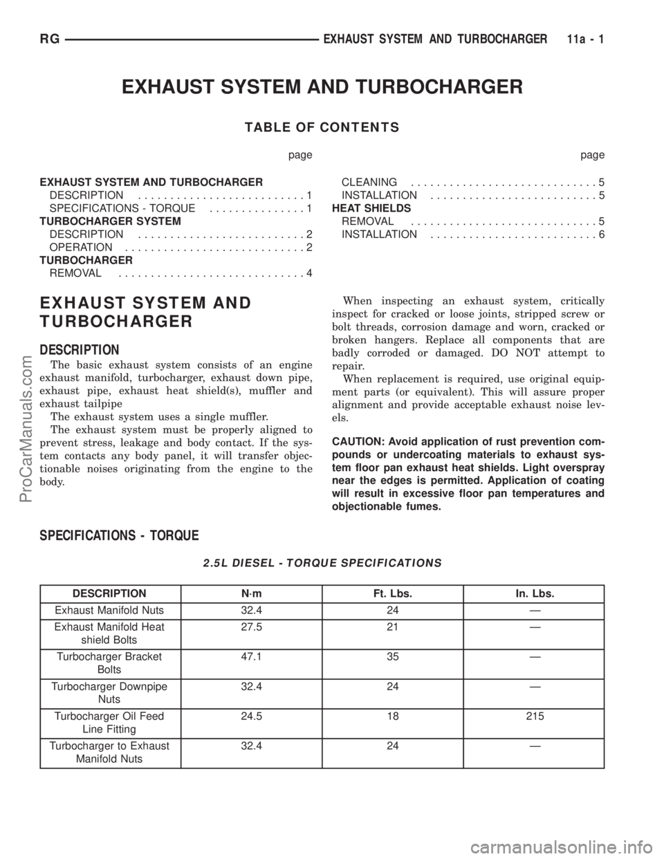
SPECIFICATIONS - TORQUE
2.5L DIESEL - TORQUE SPECIFICATIONS
DESCRIPTION N´m Ft. Lbs. In. Lbs.
Exhaust Manifold Nuts 32.4 24 Ð
Exhaust Manifold Heat
shield Bolts27.5 21 Ð
Turbocharger Bracket
Bolts47.1 35 Ð
Turbocharger Downpipe
Nuts32.4 24 Ð
Turbocharger Oil Feed
Line Fitting24.5 18 215
Turbocharger to Exhaust
Manifold Nuts32.4 24 Ð
RGEXHAUST SYSTEM AND TURBOCHARGER11a-1
ProCarManuals.com
Page 1435 of 2399
TURBOCHARGER SYSTEM
DESCRIPTION
CAUTION: The turbocharger is a performance part
and must not be tampered with. The wastegate
bracket is an integral part of the turbocharger. Tam-
pering with the wastegate components can reduce
durability by increasing cylinder pressure and ther-
mal loading due to incorrect inlet and exhaust man-
ifold pressure. Poor fuel economy and failure to
meet regulatory emissions laws may result. Increas-
ing the turbocharger boost WILL NOT increase
engine power.
The turbocharger is an exhaust-driven super-
charger which increases the pressure and density of
the air entering the engine. With the increase of air
entering the engine, more fuel can be injected into
the cylinders, which creates more power during com-
bustion.
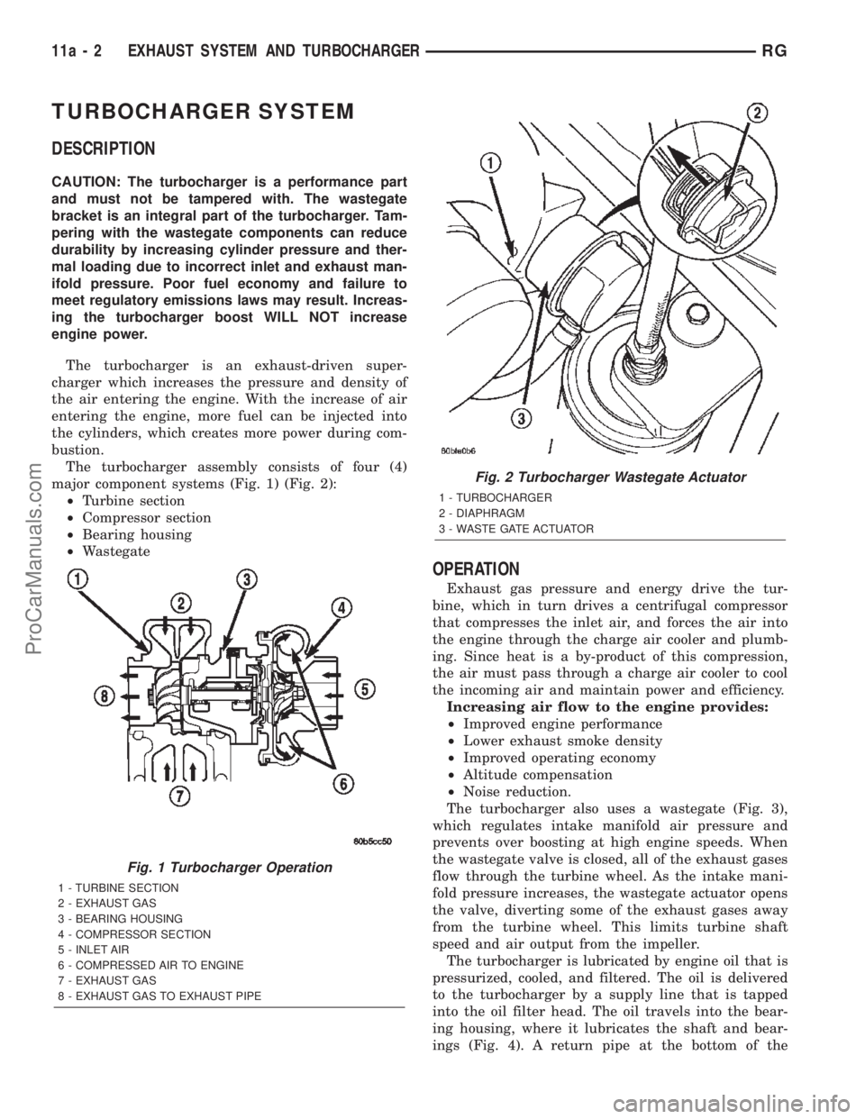
The turbocharger assembly consists of four (4)
major component systems (Fig. 1) (Fig. 2):
²Turbine section
²Compressor section
²Bearing housing
²Wastegate
OPERATION
Exhaust gas pressure and energy drive the tur-
bine, which in turn drives a centrifugal compressor
that compresses the inlet air, and forces the air into
the engine through the charge air cooler and plumb-
ing. Since heat is a by-product of this compression,
the air must pass through a charge air cooler to cool
the incoming air and maintain power and efficiency.
Increasing air flow to the engine provides:
²Improved engine performance
²Lower exhaust smoke density
²Improved operating economy
²Altitude compensation
²Noise reduction.
The turbocharger also uses a wastegate (Fig. 3),
which regulates intake manifold air pressure and
prevents over boosting at high engine speeds. When
the wastegate valve is closed, all of the exhaust gases
flow through the turbine wheel. As the intake mani-
fold pressure increases, the wastegate actuator opens
the valve, diverting some of the exhaust gases away
from the turbine wheel. This limits turbine shaft
speed and air output from the impeller.
The turbocharger is lubricated by engine oil that is
pressurized, cooled, and filtered. The oil is delivered
to the turbocharger by a supply line that is tapped
into the oil filter head. The oil travels into the bear-
ing housing, where it lubricates the shaft and bear-
ings (Fig. 4). A return pipe at the bottom of the
Fig. 1 Turbocharger Operation
1 - TURBINE SECTION
2 - EXHAUST GAS
3 - BEARING HOUSING
4 - COMPRESSOR SECTION
5 - INLET AIR
6 - COMPRESSED AIR TO ENGINE
7 - EXHAUST GAS
8 - EXHAUST GAS TO EXHAUST PIPE
Fig. 2 Turbocharger Wastegate Actuator
1 - TURBOCHARGER
2 - DIAPHRAGM
3 - WASTE GATE ACTUATOR
11a - 2 EXHAUST SYSTEM AND TURBOCHARGERRG
ProCarManuals.com
Page 1436 of 2399
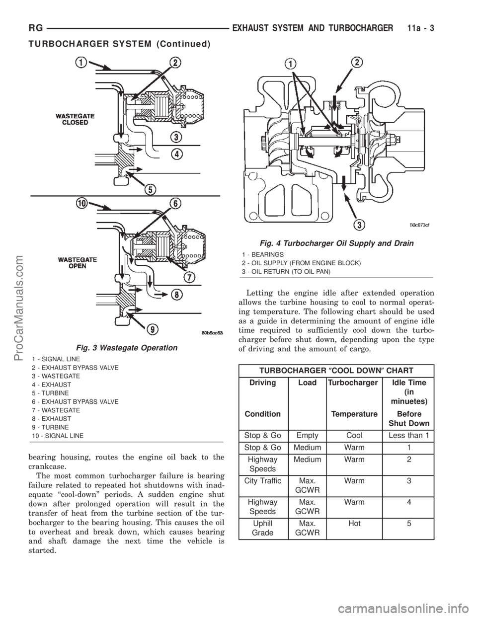
bearing housing, routes the engine oil back to the
crankcase.
The most common turbocharger failure is bearing
failure related to repeated hot shutdowns with inad-
equate ªcool-downº periods. A sudden engine shut
down after prolonged operation will result in the
transfer of heat from the turbine section of the tur-
bocharger to the bearing housing. This causes the oil
to overheat and break down, which causes bearing
and shaft damage the next time the vehicle is
started.Letting the engine idle after extended operation
allows the turbine housing to cool to normal operat-
ing temperature. The following chart should be used
as a guide in determining the amount of engine idle
time required to sufficiently cool down the turbo-
charger before shut down, depending upon the type
of driving and the amount of cargo.
TURBOCHARGER(COOL DOWN(CHART
Driving Load Turbocharger Idle Time
(in
minuetes)
Condition Temperature Before
Shut Down
Stop & Go Empty Cool Less than 1
Stop & Go Medium Warm 1
Highway
SpeedsMedium Warm 2
City Traffic Max.
GCWRWarm 3
Highway
SpeedsMax.
GCWRWarm 4
Uphill
GradeMax.
GCWRHot 5
Fig. 3 Wastegate Operation
1 - SIGNAL LINE
2 - EXHAUST BYPASS VALVE
3 - WASTEGATE
4 - EXHAUST
5 - TURBINE
6 - EXHAUST BYPASS VALVE
7 - WASTEGATE
8 - EXHAUST
9 - TURBINE
10 - SIGNAL LINE
Fig. 4 Turbocharger Oil Supply and Drain
1 - BEARINGS
2 - OIL SUPPLY (FROM ENGINE BLOCK)
3 - OIL RETURN (TO OIL PAN)
RGEXHAUST SYSTEM AND TURBOCHARGER11a-3
TURBOCHARGER SYSTEM (Continued)
ProCarManuals.com
Page 1437 of 2399
TURBOCHARGER
REMOVAL
The exhaust manifold and turbocharger cannot be
remove with the engine in vehicle.
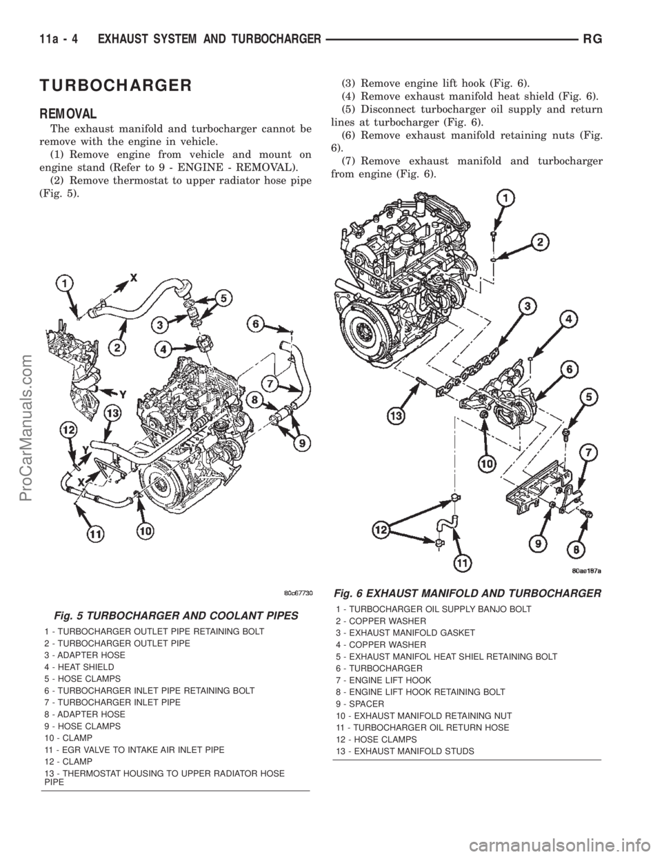
(1) Remove engine from vehicle and mount on
engine stand (Refer to 9 - ENGINE - REMOVAL).
(2) Remove thermostat to upper radiator hose pipe
(Fig. 5).(3) Remove engine lift hook (Fig. 6).
(4) Remove exhaust manifold heat shield (Fig. 6).
(5) Disconnect turbocharger oil supply and return
lines at turbocharger (Fig. 6).
(6) Remove exhaust manifold retaining nuts (Fig.
6).
(7) Remove exhaust manifold and turbocharger
from engine (Fig. 6).
Fig. 5 TURBOCHARGER AND COOLANT PIPES
1 - TURBOCHARGER OUTLET PIPE RETAINING BOLT
2 - TURBOCHARGER OUTLET PIPE
3 - ADAPTER HOSE
4 - HEAT SHIELD
5 - HOSE CLAMPS
6 - TURBOCHARGER INLET PIPE RETAINING BOLT
7 - TURBOCHARGER INLET PIPE
8 - ADAPTER HOSE
9 - HOSE CLAMPS
10 - CLAMP
11 - EGR VALVE TO INTAKE AIR INLET PIPE
12 - CLAMP
13 - THERMOSTAT HOUSING TO UPPER RADIATOR HOSE
PIPE
Fig. 6 EXHAUST MANIFOLD AND TURBOCHARGER
1 - TURBOCHARGER OIL SUPPLY BANJO BOLT
2 - COPPER WASHER
3 - EXHAUST MANIFOLD GASKET
4 - COPPER WASHER
5 - EXHAUST MANIFOL HEAT SHIEL RETAINING BOLT
6 - TURBOCHARGER
7 - ENGINE LIFT HOOK
8 - ENGINE LIFT HOOK RETAINING BOLT
9 - SPACER
10 - EXHAUST MANIFOLD RETAINING NUT
11 - TURBOCHARGER OIL RETURN HOSE
12 - HOSE CLAMPS
13 - EXHAUST MANIFOLD STUDS
11a - 4 EXHAUST SYSTEM AND TURBOCHARGERRG
ProCarManuals.com
Page 1438 of 2399
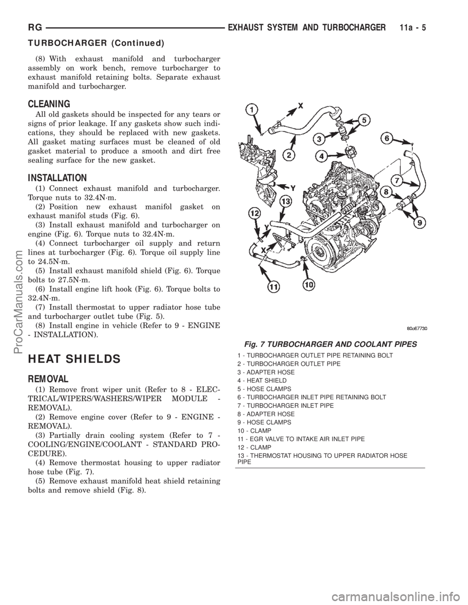
(8) With exhaust manifold and turbocharger
assembly on work bench, remove turbocharger to
exhaust manifold retaining bolts. Separate exhaust
manifold and turbocharger.
CLEANING
All old gaskets should be inspected for any tears or
signs of prior leakage. If any gaskets show such indi-
cations, they should be replaced with new gaskets.
All gasket mating surfaces must be cleaned of old
gasket material to produce a smooth and dirt free
sealing surface for the new gasket.
INSTALLATION
(1) Connect exhaust manifold and turbocharger.
Torque nuts to 32.4N´m.
(2) Position new exhaust manifol gasket on
exhaust manifol studs (Fig. 6).
(3) Install exhaust manifold and turbocharger on
engine (Fig. 6). Torque nuts to 32.4N´m.
(4) Connect turbocharger oil supply and return
lines at turbocharger (Fig. 6). Torque oil supply line
to 24.5N´m.
(5) Install exhaust manifold shield (Fig. 6). Torque
bolts to 27.5N´m.
(6) Install engine lift hook (Fig. 6). Torque bolts to
32.4N´m.
(7) Install thermostat to upper radiator hose tube
and turbocharger outlet tube (Fig. 5).
(8) Install engine in vehicle (Refer to 9 - ENGINE
- INSTALLATION).
HEAT SHIELDS
REMOVAL
(1) Remove front wiper unit (Refer to 8 - ELEC-
TRICAL/WIPERS/WASHERS/WIPER MODULE -
REMOVAL).
(2) Remove engine cover (Refer to 9 - ENGINE -
REMOVAL).
(3) Partially drain cooling system (Refer to 7 -
COOLING/ENGINE/COOLANT - STANDARD PRO-
CEDURE).
(4) Remove thermostat housing to upper radiator
hose tube (Fig. 7).
(5) Remove exhaust manifold heat shield retaining
bolts and remove shield (Fig. 8).
Fig. 7 TURBOCHARGER AND COOLANT PIPES
1 - TURBOCHARGER OUTLET PIPE RETAINING BOLT
2 - TURBOCHARGER OUTLET PIPE
3 - ADAPTER HOSE
4 - HEAT SHIELD
5 - HOSE CLAMPS
6 - TURBOCHARGER INLET PIPE RETAINING BOLT
7 - TURBOCHARGER INLET PIPE
8 - ADAPTER HOSE
9 - HOSE CLAMPS
10 - CLAMP
11 - EGR VALVE TO INTAKE AIR INLET PIPE
12 - CLAMP
13 - THERMOSTAT HOUSING TO UPPER RADIATOR HOSE
PIPE
RGEXHAUST SYSTEM AND TURBOCHARGER11a-5
TURBOCHARGER (Continued)
ProCarManuals.com
Page 1439 of 2399
INSTALLATION
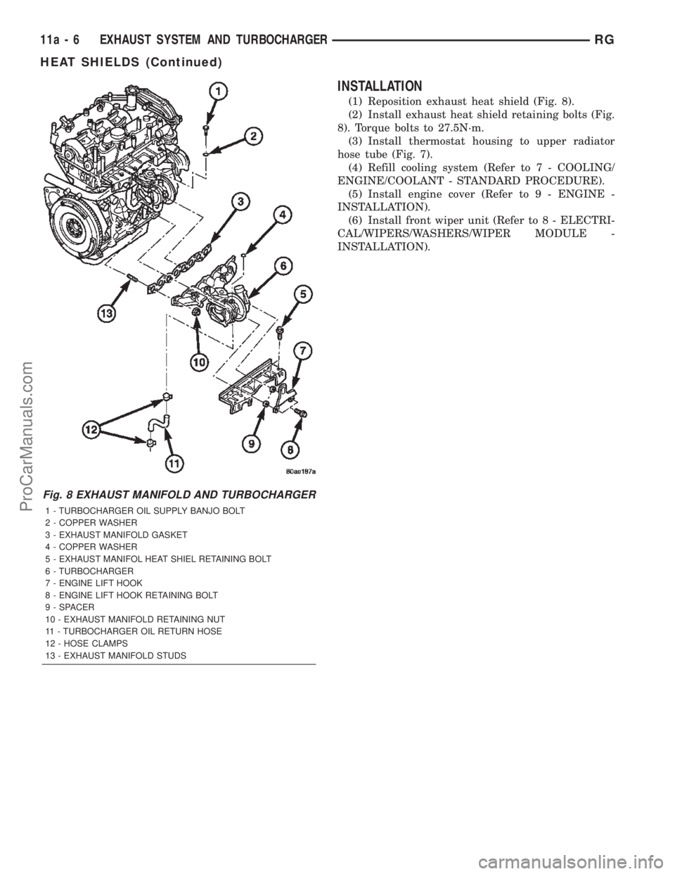
(1) Reposition exhaust heat shield (Fig. 8).
(2) Install exhaust heat shield retaining bolts (Fig.
8). Torque bolts to 27.5N´m.
(3) Install thermostat housing to upper radiator
hose tube (Fig. 7).
(4) Refill cooling system (Refer to 7 - COOLING/
ENGINE/COOLANT - STANDARD PROCEDURE).
(5) Install engine cover (Refer to 9 - ENGINE -
INSTALLATION).
(6) Install front wiper unit (Refer to 8 - ELECTRI-
CAL/WIPERS/WASHERS/WIPER MODULE -
INSTALLATION).
Fig. 8 EXHAUST MANIFOLD AND TURBOCHARGER
1 - TURBOCHARGER OIL SUPPLY BANJO BOLT
2 - COPPER WASHER
3 - EXHAUST MANIFOLD GASKET
4 - COPPER WASHER
5 - EXHAUST MANIFOL HEAT SHIEL RETAINING BOLT
6 - TURBOCHARGER
7 - ENGINE LIFT HOOK
8 - ENGINE LIFT HOOK RETAINING BOLT
9 - SPACER
10 - EXHAUST MANIFOLD RETAINING NUT
11 - TURBOCHARGER OIL RETURN HOSE
12 - HOSE CLAMPS
13 - EXHAUST MANIFOLD STUDS
11a - 6 EXHAUST SYSTEM AND TURBOCHARGERRG
HEAT SHIELDS (Continued)
ProCarManuals.com
Page 1440 of 2399

FRAME & BUMPERS
TABLE OF CONTENTS
page page
BUMPERS
SPECIFICATIONS - TORQUE...............1
FRONT FASCIA
REMOVAL.............................1
INSTALLATION..........................1
FRONT BUMPER REINFORCEMENT
REMOVAL.............................2
INSTALLATION..........................2
REAR FASCIA
REMOVAL.............................3
INSTALLATION..........................3
REAR BUMPER REINFORCEMENT
REMOVAL.............................3
INSTALLATION..........................3
REAR FASCIA - SCUFF PAD
REMOVAL.............................4INSTALLATION..........................4
FRAME
SPECIFICATIONS
FRAME DIMENSIONS...................4
SPECIFICATIONS - TORQUE.............9
FRONT CRADLE CROSSMEMBER
DESCRIPTION
DESCRIPTION - FRONT CRADLE
CROSSMEMBER.......................9
DESCRIPTION - FRONT CRADLE
CROSSMEMBER THREAD REPAIR.........9
REMOVAL.............................10
INSTALLATION.........................12
FRONT CROSSMEMBER MOUNT BUSHINGS
REMOVAL.............................12
INSTALLATION.........................12
BUMPERS
SPECIFICATIONS - TORQUE
DESCRIPTION N´m Ft. Lbs. In. Lbs.
Front bumper reinforcement attaching nut 54 40 Ð
Rear bumper reinforcement attaching nut 27 20 Ð
FRONT FASCIA
REMOVAL
(1) Release hood latch and open hood.
(2) Remove the headlamp assemblies (Refer to 8 -
ELECTRICAL/LAMPS/LIGHTING - EXTERIOR/
HEADLAMP - REMOVAL).
(3) Hoist vehicle and support with safety stands.
(4) Remove the five bolts attaching bottom of fas-
cia/air dam to radiator closure panel.
(5) Remove front wheels.
(6) Remove front wheelhouse splash shields fasten-
ers as necessary to gain access to bolts attaching
front fascia to fender. (Refer to 23 - BODY/EXTERI-
OR/ WHEELHOUSE SPLASH SHIELD - REMOV-
AL).
(7) Remove the two bolts and two nuts attaching
fascia to the front fenders (Fig. 1).
(8) Disconnect fog lamp wire connectors, if neces-
sary.
(9) Lower vehicle.(10) Remove two bolts attaching the upper grille
support to the headlamp mounting panel at each side
of the grille.
(11) Remove bumper fascia from vehicle.
INSTALLATION
(1) Position front bumper fascia on vehicle.
(2) Install the two bolts attaching fascia to head-
lamp mounting panel at each side of grille.
(3) Hoist vehicle and support with safety stands.
(4) Install the two bolts and two nuts attaching
fascia to the front fenders (Fig. 1). The fascia should
be flush to fender.
(5) Install front wheelhouse splash shields fasten-
ers. (Refer to 23 - BODY/EXTERIOR/ WHEEL-
HOUSE SPLASH SHIELD - INSTALLATION).
(6) Install front wheels.
(7) Connect fog lamp wire connectors, if necessary.
(8) Install the five bolts attaching bottom of fascia
to radiator closure panel.
(9) Lower the vehicle.
RSFRAME & BUMPERS13-1
ProCarManuals.com