compressor CHRYSLER VOYAGER 2002 Service Manual
[x] Cancel search | Manufacturer: CHRYSLER, Model Year: 2002, Model line: VOYAGER, Model: CHRYSLER VOYAGER 2002Pages: 2399, PDF Size: 57.96 MB
Page 45 of 2399
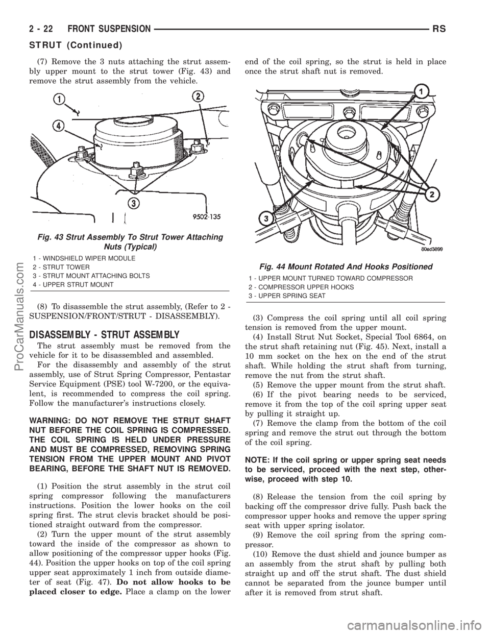
(7) Remove the 3 nuts attaching the strut assem-
bly upper mount to the strut tower (Fig. 43) and
remove the strut assembly from the vehicle.
(8) To disassemble the strut assembly, (Refer to 2 -
SUSPENSION/FRONT/STRUT - DISASSEMBLY).
DISASSEMBLY - STRUT ASSEMBLY
The strut assembly must be removed from the
vehicle for it to be disassembled and assembled.
For the disassembly and assembly of the strut
assembly, use of Strut Spring Compressor, Pentastar
Service Equipment (PSE) tool W-7200, or the equiva-
lent, is recommended to compress the coil spring.
Follow the manufacturer's instructions closely.
WARNING: DO NOT REMOVE THE STRUT SHAFT
NUT BEFORE THE COIL SPRING IS COMPRESSED.
THE COIL SPRING IS HELD UNDER PRESSURE
AND MUST BE COMPRESSED, REMOVING SPRING
TENSION FROM THE UPPER MOUNT AND PIVOT
BEARING, BEFORE THE SHAFT NUT IS REMOVED.
(1) Position the strut assembly in the strut coil
spring compressor following the manufacturers
instructions. Position the lower hooks on the coil
spring first. The strut clevis bracket should be posi-
tioned straight outward from the compressor.
(2) Turn the upper mount of the strut assembly
toward the inside of the compressor as shown to
allow positioning of the compressor upper hooks (Fig.
44). Position the upper hooks on top of the coil spring
upper seat approximately 1 inch from outside diame-
ter of seat (Fig. 47).Do not allow hooks to be
placed closer to edge.Place a clamp on the lowerend of the coil spring, so the strut is held in place
once the strut shaft nut is removed.
(3) Compress the coil spring until all coil spring
tension is removed from the upper mount.
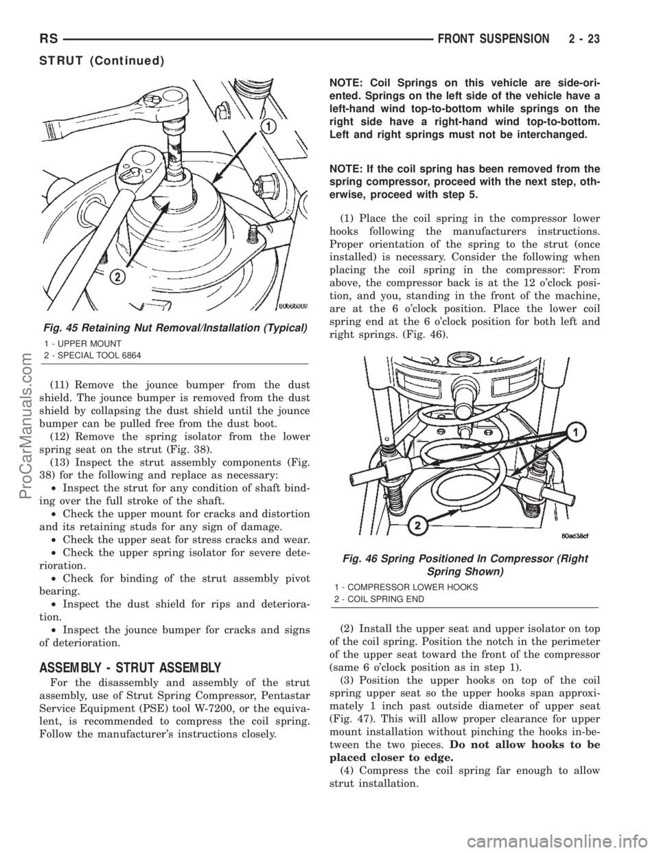
(4) Install Strut Nut Socket, Special Tool 6864, on
the strut shaft retaining nut (Fig. 45). Next, install a
10 mm socket on the hex on the end of the strut
shaft. While holding the strut shaft from turning,
remove the nut from the strut shaft.
(5) Remove the upper mount from the strut shaft.
(6) If the pivot bearing needs to be serviced,
remove it from the top of the coil spring upper seat
by pulling it straight up.
(7) Remove the clamp from the bottom of the coil
spring and remove the strut out through the bottom
of the coil spring.
NOTE: If the coil spring or upper spring seat needs
to be serviced, proceed with the next step, other-
wise, proceed with step 10.
(8) Release the tension from the coil spring by
backing off the compressor drive fully. Push back the
compressor upper hooks and remove the upper spring
seat with upper spring isolator.
(9) Remove the coil spring from the spring com-
pressor.
(10) Remove the dust shield and jounce bumper as
an assembly from the strut shaft by pulling both
straight up and off the strut shaft. The dust shield
cannot be separated from the jounce bumper until
after it is removed from strut shaft.
Fig. 43 Strut Assembly To Strut Tower Attaching
Nuts (Typical)
1 - WINDSHIELD WIPER MODULE
2 - STRUT TOWER
3 - STRUT MOUNT ATTACHING BOLTS
4 - UPPER STRUT MOUNT
Fig. 44 Mount Rotated And Hooks Positioned
1 - UPPER MOUNT TURNED TOWARD COMPRESSOR
2 - COMPRESSOR UPPER HOOKS
3 - UPPER SPRING SEAT
2 - 22 FRONT SUSPENSIONRS
STRUT (Continued)
ProCarManuals.com
Page 46 of 2399
(11) Remove the jounce bumper from the dust
shield. The jounce bumper is removed from the dust
shield by collapsing the dust shield until the jounce
bumper can be pulled free from the dust boot.
(12) Remove the spring isolator from the lower
spring seat on the strut (Fig. 38).
(13) Inspect the strut assembly components (Fig.
38) for the following and replace as necessary:
²Inspect the strut for any condition of shaft bind-
ing over the full stroke of the shaft.
²Check the upper mount for cracks and distortion
and its retaining studs for any sign of damage.
²Check the upper seat for stress cracks and wear.
²Check the upper spring isolator for severe dete-
rioration.
²Check for binding of the strut assembly pivot
bearing.
²Inspect the dust shield for rips and deteriora-
tion.
²Inspect the jounce bumper for cracks and signs
of deterioration.
ASSEMBLY - STRUT ASSEMBLY
For the disassembly and assembly of the strut
assembly, use of Strut Spring Compressor, Pentastar
Service Equipment (PSE) tool W-7200, or the equiva-
lent, is recommended to compress the coil spring.
Follow the manufacturer's instructions closely.NOTE: Coil Springs on this vehicle are side-ori-
ented. Springs on the left side of the vehicle have a
left-hand wind top-to-bottom while springs on the
right side have a right-hand wind top-to-bottom.
Left and right springs must not be interchanged.
NOTE: If the coil spring has been removed from the
spring compressor, proceed with the next step, oth-
erwise, proceed with step 5.
(1) Place the coil spring in the compressor lower
hooks following the manufacturers instructions.
Proper orientation of the spring to the strut (once
installed) is necessary. Consider the following when
placing the coil spring in the compressor: From
above, the compressor back is at the 12 o'clock posi-
tion, and you, standing in the front of the machine,
are at the 6 o'clock position. Place the lower coil
spring end at the 6 o'clock position for both left and
right springs. (Fig. 46).
(2) Install the upper seat and upper isolator on top
of the coil spring. Position the notch in the perimeter
of the upper seat toward the front of the compressor
(same 6 o'clock position as in step 1).
(3) Position the upper hooks on top of the coil
spring upper seat so the upper hooks span approxi-
mately 1 inch past outside diameter of upper seat
(Fig. 47). This will allow proper clearance for upper
mount installation without pinching the hooks in-be-
tween the two pieces.Do not allow hooks to be
placed closer to edge.
(4) Compress the coil spring far enough to allow
strut installation.
Fig. 45 Retaining Nut Removal/Installation (Typical)
1 - UPPER MOUNT
2 - SPECIAL TOOL 6864
Fig. 46 Spring Positioned In Compressor (Right
Spring Shown)
1 - COMPRESSOR LOWER HOOKS
2 - COIL SPRING END
RSFRONT SUSPENSION2-23
STRUT (Continued)
ProCarManuals.com
Page 47 of 2399
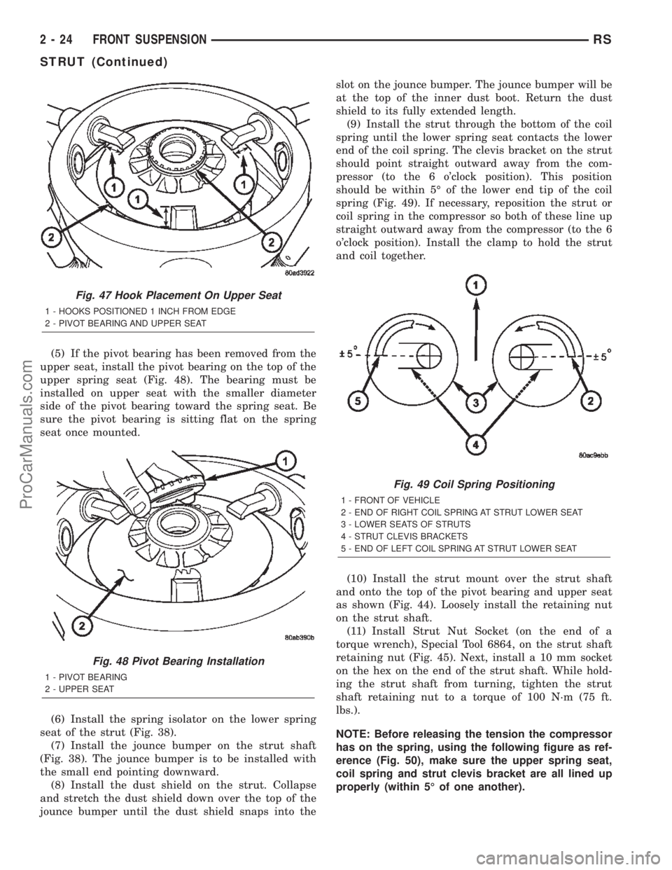
(5) If the pivot bearing has been removed from the
upper seat, install the pivot bearing on the top of the
upper spring seat (Fig. 48). The bearing must be
installed on upper seat with the smaller diameter
side of the pivot bearing toward the spring seat. Be
sure the pivot bearing is sitting flat on the spring
seat once mounted.
(6) Install the spring isolator on the lower spring
seat of the strut (Fig. 38).
(7) Install the jounce bumper on the strut shaft
(Fig. 38). The jounce bumper is to be installed with
the small end pointing downward.
(8) Install the dust shield on the strut. Collapse
and stretch the dust shield down over the top of the
jounce bumper until the dust shield snaps into theslot on the jounce bumper. The jounce bumper will be
at the top of the inner dust boot. Return the dust
shield to its fully extended length.
(9) Install the strut through the bottom of the coil
spring until the lower spring seat contacts the lower
end of the coil spring. The clevis bracket on the strut
should point straight outward away from the com-
pressor (to the 6 o'clock position). This position
should be within 5É of the lower end tip of the coil
spring (Fig. 49). If necessary, reposition the strut or
coil spring in the compressor so both of these line up
straight outward away from the compressor (to the 6
o'clock position). Install the clamp to hold the strut
and coil together.
(10) Install the strut mount over the strut shaft
and onto the top of the pivot bearing and upper seat
as shown (Fig. 44). Loosely install the retaining nut
on the strut shaft.
(11) Install Strut Nut Socket (on the end of a
torque wrench), Special Tool 6864, on the strut shaft
retaining nut (Fig. 45). Next, install a 10 mm socket
on the hex on the end of the strut shaft. While hold-
ing the strut shaft from turning, tighten the strut
shaft retaining nut to a torque of 100 N´m (75 ft.
lbs.).
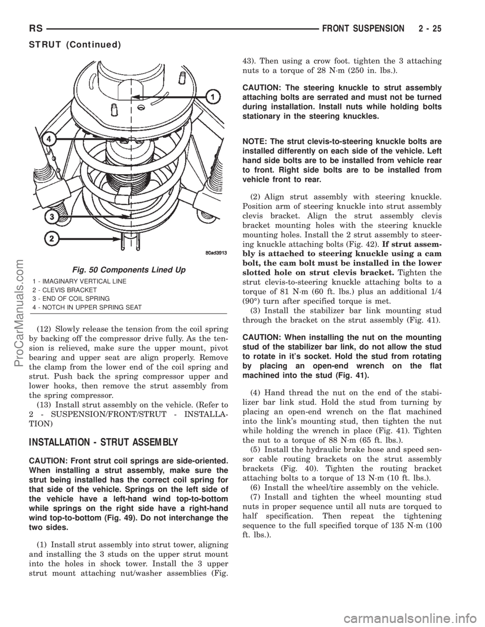
NOTE: Before releasing the tension the compressor
has on the spring, using the following figure as ref-
erence (Fig. 50), make sure the upper spring seat,
coil spring and strut clevis bracket are all lined up
properly (within 5É of one another).
Fig. 47 Hook Placement On Upper Seat
1 - HOOKS POSITIONED 1 INCH FROM EDGE
2 - PIVOT BEARING AND UPPER SEAT
Fig. 48 Pivot Bearing Installation
1 - PIVOT BEARING
2 - UPPER SEAT
Fig. 49 Coil Spring Positioning
1 - FRONT OF VEHICLE
2 - END OF RIGHT COIL SPRING AT STRUT LOWER SEAT
3 - LOWER SEATS OF STRUTS
4 - STRUT CLEVIS BRACKETS
5 - END OF LEFT COIL SPRING AT STRUT LOWER SEAT
2 - 24 FRONT SUSPENSIONRS
STRUT (Continued)
ProCarManuals.com
Page 48 of 2399
(12) Slowly release the tension from the coil spring
by backing off the compressor drive fully. As the ten-
sion is relieved, make sure the upper mount, pivot
bearing and upper seat are align properly. Remove
the clamp from the lower end of the coil spring and
strut. Push back the spring compressor upper and
lower hooks, then remove the strut assembly from
the spring compressor.
(13) Install strut assembly on the vehicle. (Refer to
2 - SUSPENSION/FRONT/STRUT - INSTALLA-
TION)
INSTALLATION - STRUT ASSEMBLY
CAUTION: Front strut coil springs are side-oriented.
When installing a strut assembly, make sure the
strut being installed has the correct coil spring for
that side of the vehicle. Springs on the left side of
the vehicle have a left-hand wind top-to-bottom
while springs on the right side have a right-hand
wind top-to-bottom (Fig. 49). Do not interchange the
two sides.
(1) Install strut assembly into strut tower, aligning
and installing the 3 studs on the upper strut mount
into the holes in shock tower. Install the 3 upper
strut mount attaching nut/washer assemblies (Fig.43). Then using a crow foot. tighten the 3 attaching
nuts to a torque of 28 N´m (250 in. lbs.).
CAUTION: The steering knuckle to strut assembly
attaching bolts are serrated and must not be turned
during installation. Install nuts while holding bolts
stationary in the steering knuckles.
NOTE: The strut clevis-to-steering knuckle bolts are
installed differently on each side of the vehicle. Left
hand side bolts are to be installed from vehicle rear
to front. Right side bolts are to be installed from
vehicle front to rear.
(2) Align strut assembly with steering knuckle.
Position arm of steering knuckle into strut assembly
clevis bracket. Align the strut assembly clevis
bracket mounting holes with the steering knuckle
mounting holes. Install the 2 strut assembly to steer-
ing knuckle attaching bolts (Fig. 42).If strut assem-
bly is attached to steering knuckle using a cam
bolt, the cam bolt must be installed in the lower
slotted hole on strut clevis bracket.Tighten the
strut clevis-to-steering knuckle attaching bolts to a
torque of 81 N´m (60 ft. lbs.) plus an additional 1/4
(90É) turn after specified torque is met.
(3) Install the stabilizer bar link mounting stud
through the bracket on the strut assembly (Fig. 41).
CAUTION: When installing the nut on the mounting
stud of the stabilizer bar link, do not allow the stud
to rotate in it's socket. Hold the stud from rotating
by placing an open-end wrench on the flat
machined into the stud (Fig. 41).
(4) Hand thread the nut on the end of the stabi-
lizer bar link stud. Hold the stud from turning by
placing an open-end wrench on the flat machined
into the link's mounting stud, then tighten the nut
while holding the wrench in place (Fig. 41). Tighten
the nut to a torque of 88 N´m (65 ft. lbs.).
(5) Install the hydraulic brake hose and speed sen-
sor cable routing brackets on the strut assembly
brackets (Fig. 40). Tighten the routing bracket
attaching bolts to a torque of 13 N´m (10 ft. lbs.).
(6) Install the wheel/tire assembly on the vehicle.
(7) Install and tighten the wheel mounting stud
nuts in proper sequence until all nuts are torqued to
half specification. Then repeat the tightening
sequence to the full specified torque of 135 N´m (100
ft. lbs.).
Fig. 50 Components Lined Up
1 - IMAGINARY VERTICAL LINE
2 - CLEVIS BRACKET
3 - END OF COIL SPRING
4 - NOTCH IN UPPER SPRING SEAT
RSFRONT SUSPENSION2-25
STRUT (Continued)
ProCarManuals.com
Page 60 of 2399
SHOCK ABSORBER
DESCRIPTION
There is one shock absorber on each side of the
rear suspension. The top of each shock absorber is
bolted to the frame rail. The bottom of each shock
absorber is bolted to the rear axle.
This vehicle is available with either standard type
or load-leveling shock absorbers. On the exterior,
load-leveling shock absorbers are larger in diameter
than standard shock absorbers. The load-leveling
shock absorbers mount the same as the standard
shock absorbers.
OPERATION
The shock absorber dampens jounce and rebound
motions of the spring and suspension.
Each load-leveling shock absorber is a self-leveling,
self-contained vehicle leveling system and shock
absorber combined. It does not require an external
compressor, hoses, or height leveling sensors. All the
height leveling sensors, hydraulic pump, etc., are con-
tained inside the shock absorber. It uses road inputs
(bumps, stops, starts, turns, acceleration, deceleration,
etc.) to activate pumping, which results in the exten-
sion and compression of the shock absorber.
REMOVAL - SHOCK ABSORBER
(1) Raise vehicle. (Refer to LUBRICATION &
MAINTENANCE/HOISTING - STANDARD PROCE-
DURE)
(2) Support the rear axle of the vehicle using 2
jackstands positioned at the outer ends of the axle.
NOTE: If the shock absorber lower mounting bolt
deflects upward during removal, raise axle by
adjusting the support jack. If the lower shock
absorber bolt deflects downward during removal,
lower the axle by adjusting the support jack.
(3) Remove the shock absorber lower mounting
bolt.
(4) While holding shock absorber, remove the
shock absorber upper mounting bolt and shock
absorber.
DISASSEMBLY - SHOCK ABSORBER (UPPER
BUSHING)
NOTE: This procedure applies to load-leveling
shock absorbers only.
(1) Remove the shock absorber from the vehicle.
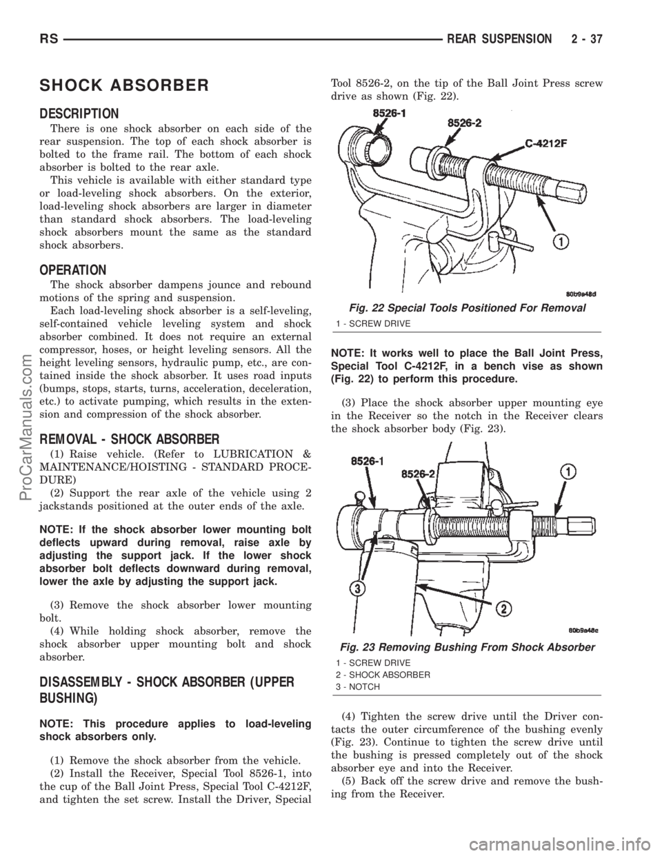
(2) Install the Receiver, Special Tool 8526-1, into
the cup of the Ball Joint Press, Special Tool C-4212F,
and tighten the set screw. Install the Driver, SpecialTool 8526-2, on the tip of the Ball Joint Press screw
drive as shown (Fig. 22).
NOTE: It works well to place the Ball Joint Press,
Special Tool C-4212F, in a bench vise as shown
(Fig. 22) to perform this procedure.
(3) Place the shock absorber upper mounting eye
in the Receiver so the notch in the Receiver clears
the shock absorber body (Fig. 23).
(4) Tighten the screw drive until the Driver con-
tacts the outer circumference of the bushing evenly
(Fig. 23). Continue to tighten the screw drive until
the bushing is pressed completely out of the shock
absorber eye and into the Receiver.
(5) Back off the screw drive and remove the bush-
ing from the Receiver.
Fig. 22 Special Tools Positioned For Removal
1 - SCREW DRIVE
Fig. 23 Removing Bushing From Shock Absorber
1 - SCREW DRIVE
2 - SHOCK ABSORBER
3 - NOTCH
RSREAR SUSPENSION2-37
ProCarManuals.com
Page 255 of 2399
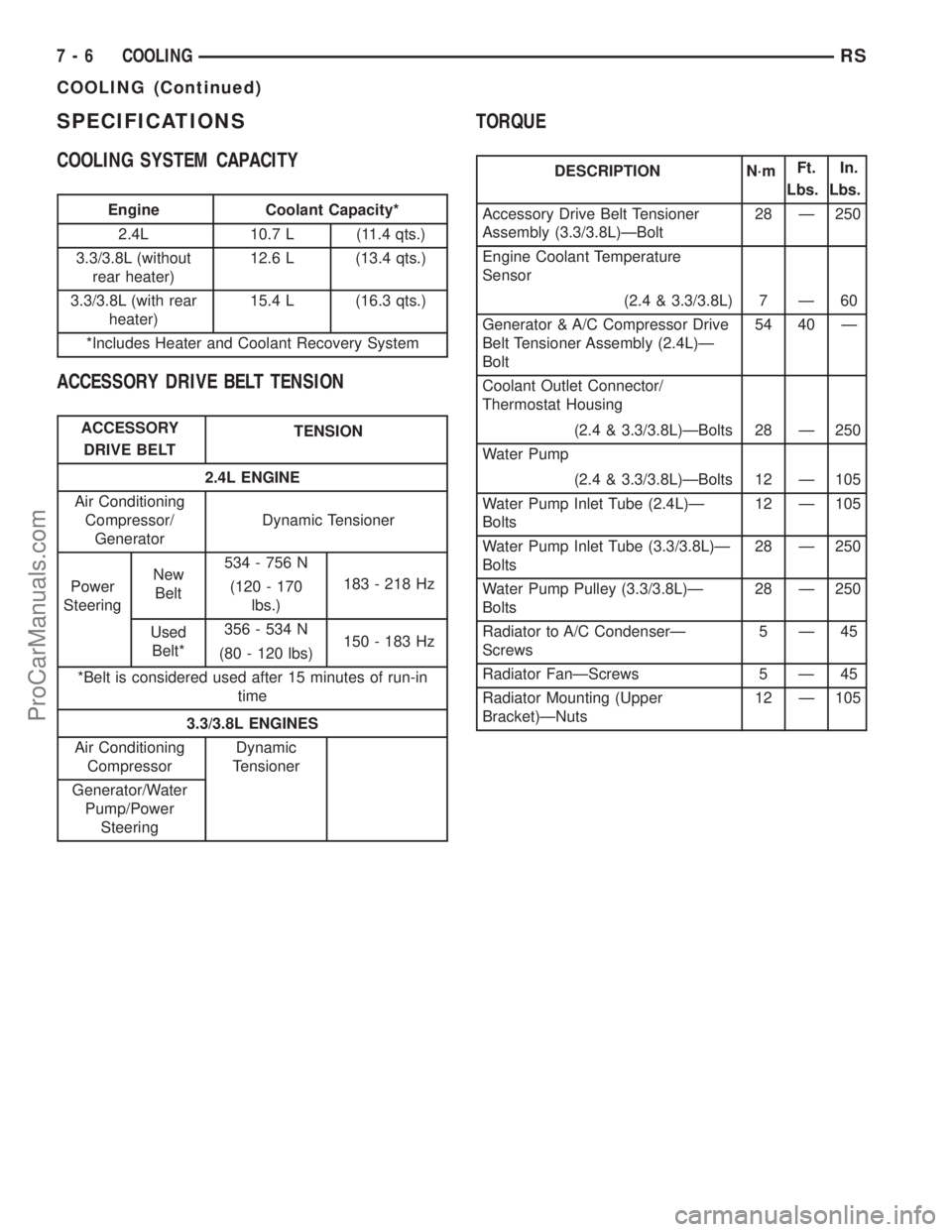
SPECIFICATIONS
COOLING SYSTEM CAPACITY
Engine Coolant Capacity*
2.4L 10.7 L (11.4 qts.)
3.3/3.8L (without
rear heater)12.6 L (13.4 qts.)
3.3/3.8L (with rear
heater)15.4 L (16.3 qts.)
*Includes Heater and Coolant Recovery System
ACCESSORY DRIVE BELT TENSION
ACCESSORY
DRIVE BELTTENSION
2.4L ENGINE
Air Conditioning
Compressor/
GeneratorDynamic Tensioner
Power
SteeringNew
Belt534 - 756 N
183 - 218 Hz
(120 - 170
lbs.)
Used
Belt*356 - 534 N
150 - 183 Hz
(80 - 120 lbs)
*Belt is considered used after 15 minutes of run-in
time
3.3/3.8L ENGINES
Air Conditioning
CompressorDynamic
Tensioner
Generator/Water
Pump/Power
Steering
TORQUE
DESCRIPTION N´mFt.
Lbs.In.
Lbs.
Accessory Drive Belt Tensioner
Assembly (3.3/3.8L)ÐBolt28 Ð 250
Engine Coolant Temperature
Sensor
(2.4 & 3.3/3.8L) 7 Ð 60
Generator & A/C Compressor Drive
Belt Tensioner Assembly (2.4L)Ð
Bolt54 40 Ð
Coolant Outlet Connector/
Thermostat Housing
(2.4 & 3.3/3.8L)ÐBolts 28 Ð 250
Water Pump
(2.4 & 3.3/3.8L)ÐBolts 12 Ð 105
Water Pump Inlet Tube (2.4L)Ð
Bolts12 Ð 105
Water Pump Inlet Tube (3.3/3.8L)Ð
Bolts28 Ð 250
Water Pump Pulley (3.3/3.8L)Ð
Bolts28 Ð 250
Radiator to A/C CondenserÐ
Screws5Ð45
Radiator FanÐScrews 5 Ð 45
Radiator Mounting (Upper
Bracket)ÐNuts12 Ð 105
7 - 6 COOLINGRS
COOLING (Continued)
ProCarManuals.com
Page 257 of 2399
ACCESSORY DRIVE
TABLE OF CONTENTS
page page
BELT TENSIONER - 2.4L
REMOVAL.............................8
INSTALLATION..........................8
BELT TENSIONER - 3.3/3.8L
REMOVAL.............................8
INSTALLATION..........................8
DRIVE BELTS
DESCRIPTION..........................9
OPERATION............................9
DIAGNOSIS AND TESTING - ACCESSORY
DRIVE BELT..........................9
DRIVE BELTS - 2.4L
STANDARD PROCEDURE - CHECKING
POWER STEERING BELT TENSION.......10REMOVAL.............................10
CLEANING............................11
INSPECTION..........................11
INSTALLATION.........................11
ADJUSTMENTS........................12
DRIVE BELTS - 3.3/3.8L
REMOVAL.............................12
CLEANING............................13
INSPECTION..........................13
INSTALLATION.........................13
BELT TENSIONER - 2.4L
REMOVAL
(1) Raise vehicle on hoist.
(2) Remove the drive belt shield.
(3) Remove the generator/A/C drive belt. (Refer to
7 - COOLING/ACCESSORY DRIVE/DRIVE BELTS -
REMOVAL)
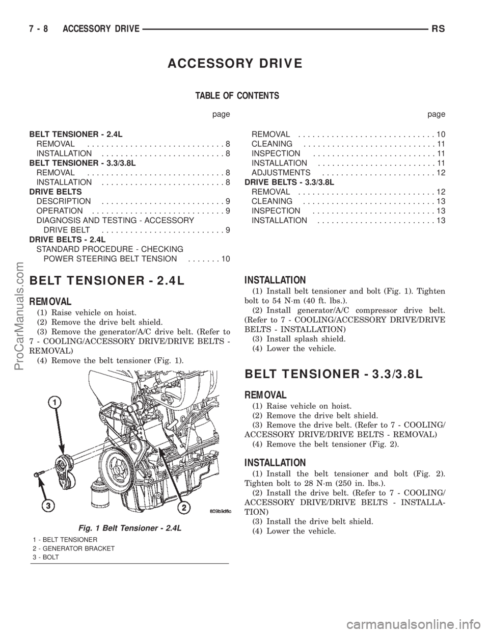
(4) Remove the belt tensioner (Fig. 1).
INSTALLATION
(1) Install belt tensioner and bolt (Fig. 1). Tighten
bolt to 54 N´m (40 ft. lbs.).
(2) Install generator/A/C compressor drive belt.
(Refer to 7 - COOLING/ACCESSORY DRIVE/DRIVE
BELTS - INSTALLATION)
(3) Install splash shield.
(4) Lower the vehicle.
BELT TENSIONER - 3.3/3.8L
REMOVAL
(1) Raise vehicle on hoist.
(2) Remove the drive belt shield.
(3) Remove the drive belt. (Refer to 7 - COOLING/
ACCESSORY DRIVE/DRIVE BELTS - REMOVAL)
(4) Remove the belt tensioner (Fig. 2).
INSTALLATION
(1) Install the belt tensioner and bolt (Fig. 2).
Tighten bolt to 28 N´m (250 in. lbs.).
(2) Install the drive belt. (Refer to 7 - COOLING/
ACCESSORY DRIVE/DRIVE BELTS - INSTALLA-
TION)
(3) Install the drive belt shield.
(4) Lower the vehicle.
Fig. 1 Belt Tensioner - 2.4L
1 - BELT TENSIONER
2 - GENERATOR BRACKET
3 - BOLT
7 - 8 ACCESSORY DRIVERS
ProCarManuals.com
Page 259 of 2399
CONDITION POSSIBLE CAUSES CORRECTIONS
BELT ROLLED OVER IN GROOVE
OR BELT JUMPS OFF1. Broken cord in belt 1. Replace belt
2. Belt too loose, or too tight 2. (a) Replace belt (auto-tensioned
belts.)
(b) Adjust power steering belt
tension (4 cyl. engine)
3. Misaligned pulleys 3. Align accessories
4. Non-uniform groove or eccentric
pulley4. Replace pulley
DRIVE BELTS - 2.4L
STANDARD PROCEDURE - CHECKING POWER
STEERING BELT TENSION
WARNING: DO NOT CHECK BELT TENSION WITH
ENGINE RUNNING.
Accessory drive belt tension can be measured with
Special Tool 8371 ± Belt Tension Gauge Adapter, and
the DRBIIItusing the following procedures:
(1) Connect 8371 to the DRBIIItfollowing the
instructions provided with tool.
(2) Place end of microphone probe approximately
2.54 cm (1 in.) from belt at belt center span location
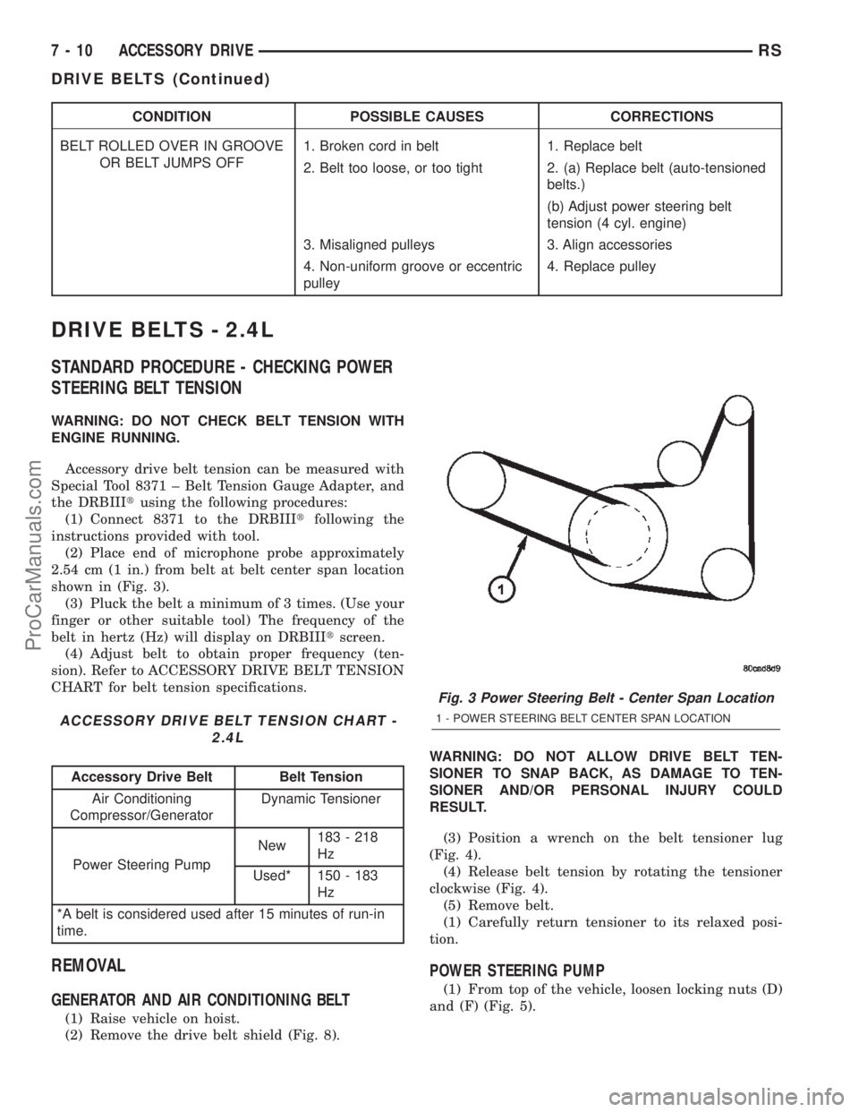
shown in (Fig. 3).
(3) Pluck the belt a minimum of 3 times. (Use your
finger or other suitable tool) The frequency of the
belt in hertz (Hz) will display on DRBIIItscreen.
(4) Adjust belt to obtain proper frequency (ten-
sion). Refer to ACCESSORY DRIVE BELT TENSION
CHART for belt tension specifications.
ACCESSORY DRIVE BELT TENSION CHART -
2.4L
Accessory Drive Belt Belt Tension
Air Conditioning
Compressor/GeneratorDynamic Tensioner
Power Steering PumpNew183 - 218
Hz
Used* 150 - 183
Hz
*A belt is considered used after 15 minutes of run-in
time.
REMOVAL
GENERATOR AND AIR CONDITIONING BELT
(1) Raise vehicle on hoist.
(2) Remove the drive belt shield (Fig. 8).WARNING: DO NOT ALLOW DRIVE BELT TEN-
SIONER TO SNAP BACK, AS DAMAGE TO TEN-
SIONER AND/OR PERSONAL INJURY COULD
RESULT.
(3) Position a wrench on the belt tensioner lug
(Fig. 4).
(4) Release belt tension by rotating the tensioner
clockwise (Fig. 4).
(5) Remove belt.
(1) Carefully return tensioner to its relaxed posi-
tion.
POWER STEERING PUMP
(1) From top of the vehicle, loosen locking nuts (D)
and (F) (Fig. 5).
Fig. 3 Power Steering Belt - Center Span Location
1 - POWER STEERING BELT CENTER SPAN LOCATION
7 - 10 ACCESSORY DRIVERS
DRIVE BELTS (Continued)
ProCarManuals.com
Page 261 of 2399
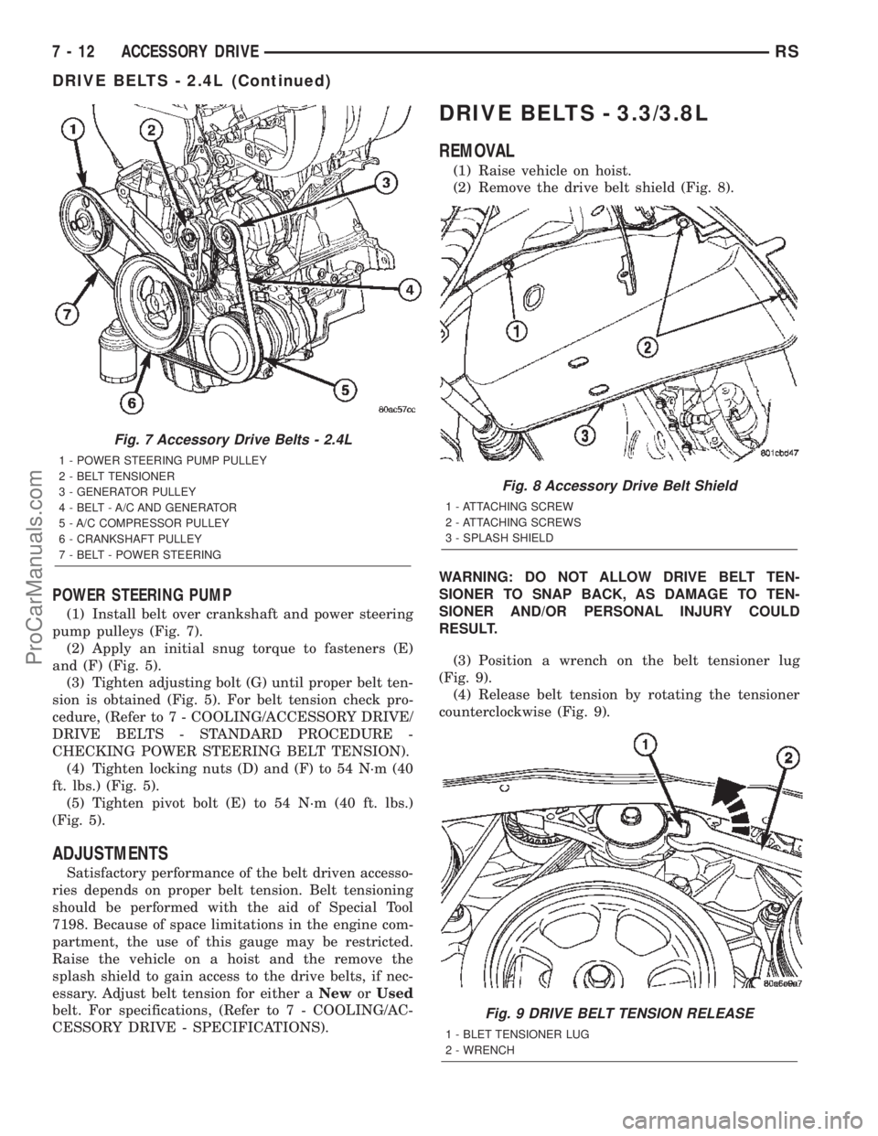
POWER STEERING PUMP
(1) Install belt over crankshaft and power steering
pump pulleys (Fig. 7).
(2) Apply an initial snug torque to fasteners (E)
and (F) (Fig. 5).
(3) Tighten adjusting bolt (G) until proper belt ten-
sion is obtained (Fig. 5). For belt tension check pro-
cedure, (Refer to 7 - COOLING/ACCESSORY DRIVE/
DRIVE BELTS - STANDARD PROCEDURE -
CHECKING POWER STEERING BELT TENSION).
(4) Tighten locking nuts (D) and (F) to 54 N´m (40
ft. lbs.) (Fig. 5).
(5) Tighten pivot bolt (E) to 54 N´m (40 ft. lbs.)
(Fig. 5).
ADJUSTMENTS
Satisfactory performance of the belt driven accesso-
ries depends on proper belt tension. Belt tensioning
should be performed with the aid of Special Tool
7198. Because of space limitations in the engine com-
partment, the use of this gauge may be restricted.
Raise the vehicle on a hoist and the remove the
splash shield to gain access to the drive belts, if nec-
essary. Adjust belt tension for either aNeworUsed
belt. For specifications, (Refer to 7 - COOLING/AC-
CESSORY DRIVE - SPECIFICATIONS).
DRIVE BELTS - 3.3/3.8L
REMOVAL
(1) Raise vehicle on hoist.
(2) Remove the drive belt shield (Fig. 8).
WARNING: DO NOT ALLOW DRIVE BELT TEN-
SIONER TO SNAP BACK, AS DAMAGE TO TEN-
SIONER AND/OR PERSONAL INJURY COULD
RESULT.
(3) Position a wrench on the belt tensioner lug
(Fig. 9).
(4) Release belt tension by rotating the tensioner
counterclockwise (Fig. 9).
Fig. 7 Accessory Drive Belts - 2.4L
1 - POWER STEERING PUMP PULLEY
2 - BELT TENSIONER
3 - GENERATOR PULLEY
4 - BELT - A/C AND GENERATOR
5 - A/C COMPRESSOR PULLEY
6 - CRANKSHAFT PULLEY
7 - BELT - POWER STEERING
Fig. 8 Accessory Drive Belt Shield
1 - ATTACHING SCREW
2 - ATTACHING SCREWS
3 - SPLASH SHIELD
Fig. 9 DRIVE BELT TENSION RELEASE
1 - BLET TENSIONER LUG
2 - WRENCH
7 - 12 ACCESSORY DRIVERS
DRIVE BELTS - 2.4L (Continued)
ProCarManuals.com
Page 262 of 2399
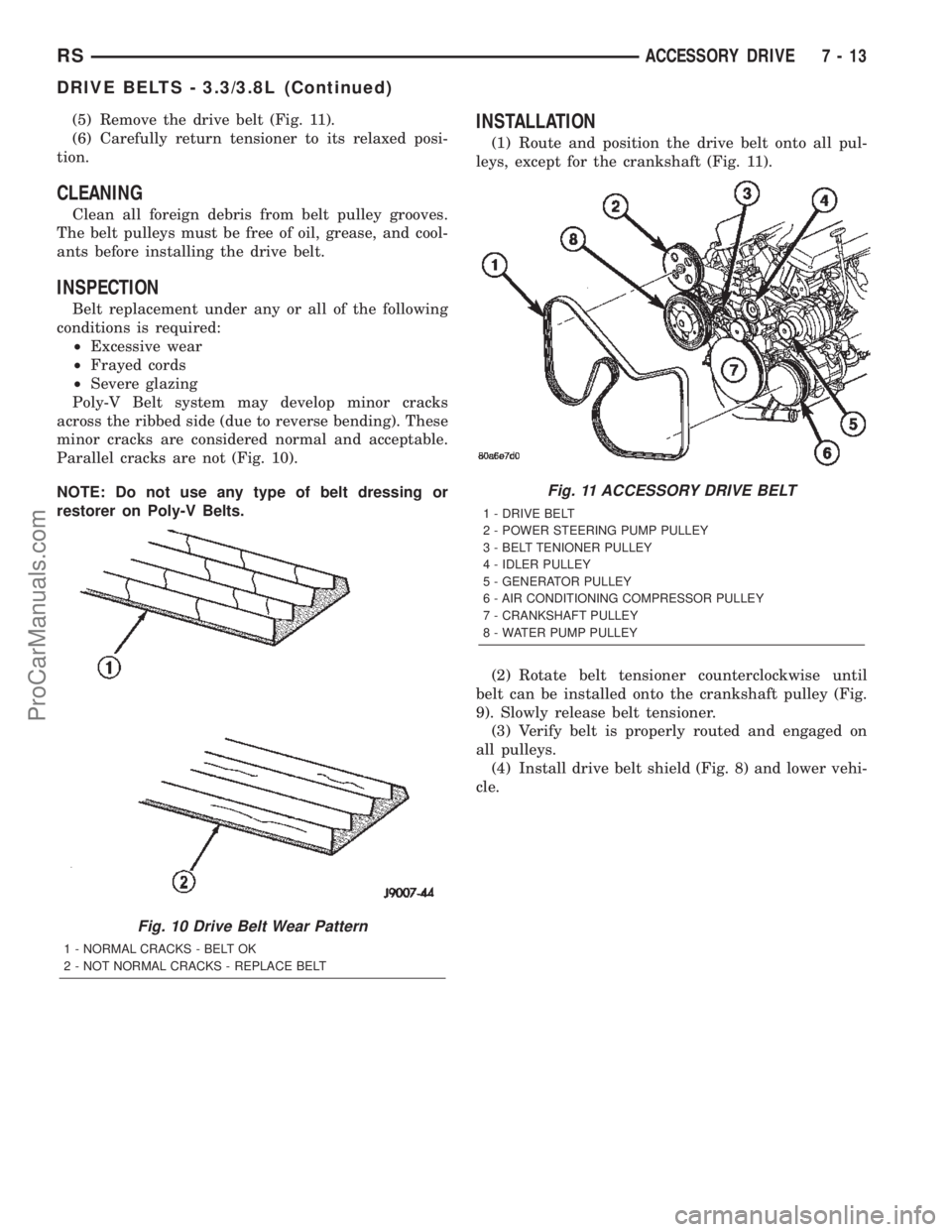
(5) Remove the drive belt (Fig. 11).
(6) Carefully return tensioner to its relaxed posi-
tion.
CLEANING
Clean all foreign debris from belt pulley grooves.
The belt pulleys must be free of oil, grease, and cool-
ants before installing the drive belt.
INSPECTION
Belt replacement under any or all of the following
conditions is required:
²Excessive wear
²Frayed cords
²Severe glazing
Poly-V Belt system may develop minor cracks
across the ribbed side (due to reverse bending). These
minor cracks are considered normal and acceptable.
Parallel cracks are not (Fig. 10).
NOTE: Do not use any type of belt dressing or
restorer on Poly-V Belts.
INSTALLATION
(1) Route and position the drive belt onto all pul-
leys, except for the crankshaft (Fig. 11).
(2) Rotate belt tensioner counterclockwise until
belt can be installed onto the crankshaft pulley (Fig.
9). Slowly release belt tensioner.
(3) Verify belt is properly routed and engaged on
all pulleys.
(4) Install drive belt shield (Fig. 8) and lower vehi-
cle.
Fig. 10 Drive Belt Wear Pattern
1 - NORMAL CRACKS - BELT OK
2 - NOT NORMAL CRACKS - REPLACE BELT
Fig. 11 ACCESSORY DRIVE BELT
1 - DRIVE BELT
2 - POWER STEERING PUMP PULLEY
3 - BELT TENIONER PULLEY
4 - IDLER PULLEY
5 - GENERATOR PULLEY
6 - AIR CONDITIONING COMPRESSOR PULLEY
7 - CRANKSHAFT PULLEY
8 - WATER PUMP PULLEY
RSACCESSORY DRIVE7-13
DRIVE BELTS - 3.3/3.8L (Continued)
ProCarManuals.com