CHRYSLER VOYAGER 2002 Service Manual
Manufacturer: CHRYSLER, Model Year: 2002, Model line: VOYAGER, Model: CHRYSLER VOYAGER 2002Pages: 2399, PDF Size: 57.96 MB
Page 1831 of 2399
(8) Position an appropriate piece of Plastigage
across both pump gears.
(9) Align the Plastigage to a flat area on the reac-
tion shaft support housing.
(10) Install the reaction shaft to the pump hous-
ing. Tighten the bolts to 27 N´m (20 ft. lbs.).
(11) Remove bolts and carefully separate the hous-
ings. Measure the Plastigage following the instruc-
tions supplied.
(12) Clearance between outer gear side and the
reaction shaft support should be 0.020-0.046 mm
(0.0008-0.0018 in.). Clearance between inner gear
side and the reaction shaft support should be 0.020-
0.046 mm (0.0008-0.0018 in.).
ASSEMBLY
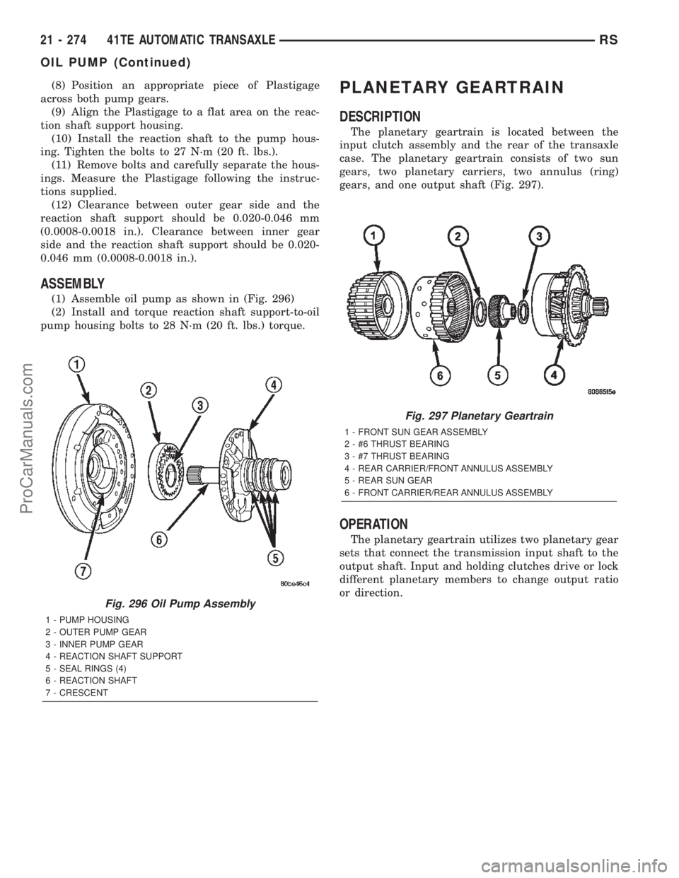
(1) Assemble oil pump as shown in (Fig. 296)
(2) Install and torque reaction shaft support-to-oil
pump housing bolts to 28 N´m (20 ft. lbs.) torque.
PLANETARY GEARTRAIN
DESCRIPTION
The planetary geartrain is located between the
input clutch assembly and the rear of the transaxle
case. The planetary geartrain consists of two sun
gears, two planetary carriers, two annulus (ring)
gears, and one output shaft (Fig. 297).
OPERATION
The planetary geartrain utilizes two planetary gear
sets that connect the transmission input shaft to the
output shaft. Input and holding clutches drive or lock
different planetary members to change output ratio
or direction.
Fig. 296 Oil Pump Assembly
1 - PUMP HOUSING
2 - OUTER PUMP GEAR
3 - INNER PUMP GEAR
4 - REACTION SHAFT SUPPORT
5 - SEAL RINGS (4)
6 - REACTION SHAFT
7 - CRESCENT
Fig. 297 Planetary Geartrain
1 - FRONT SUN GEAR ASSEMBLY
2 - #6 THRUST BEARING
3 - #7 THRUST BEARING
4 - REAR CARRIER/FRONT ANNULUS ASSEMBLY
5 - REAR SUN GEAR
6 - FRONT CARRIER/REAR ANNULUS ASSEMBLY
21 - 274 41TE AUTOMATIC TRANSAXLERS
OIL PUMP (Continued)
ProCarManuals.com
Page 1832 of 2399
SEAL - OIL PUMP
REMOVAL
(1) Remove transaxle from vehicle (Refer to 21 -
TRANSMISSION/TRANSAXLE/AUTOMATIC - 41TE
- REMOVAL).
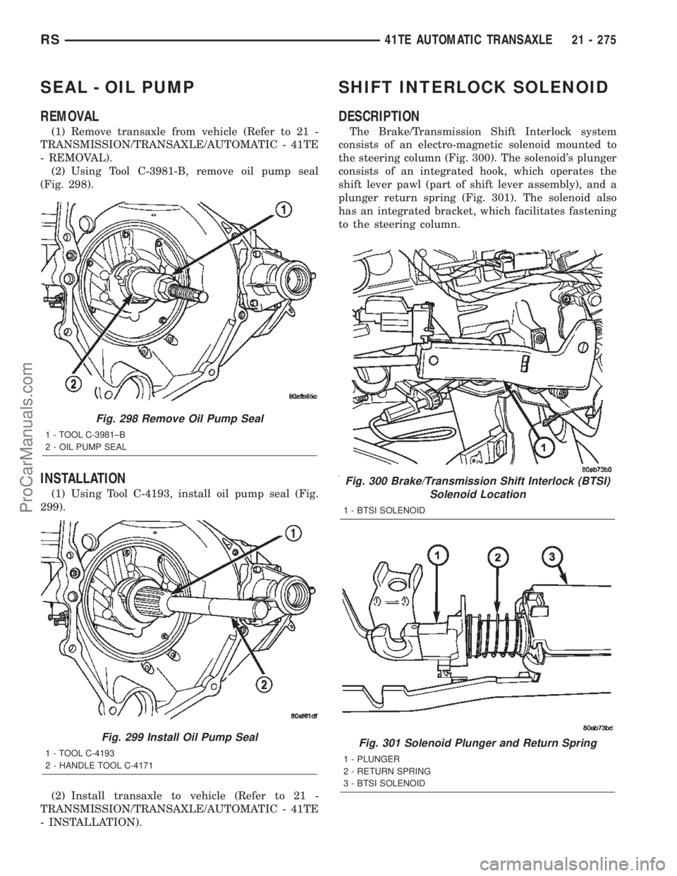
(2) Using Tool C-3981-B, remove oil pump seal
(Fig. 298).
INSTALLATION
(1) Using Tool C-4193, install oil pump seal (Fig.
299).
(2) Install transaxle to vehicle (Refer to 21 -
TRANSMISSION/TRANSAXLE/AUTOMATIC - 41TE
- INSTALLATION).
SHIFT INTERLOCK SOLENOID
DESCRIPTION
The Brake/Transmission Shift Interlock system
consists of an electro-magnetic solenoid mounted to
the steering column (Fig. 300). The solenoid's plunger
consists of an integrated hook, which operates the
shift lever pawl (part of shift lever assembly), and a
plunger return spring (Fig. 301). The solenoid also
has an integrated bracket, which facilitates fastening
to the steering column.
Fig. 298 Remove Oil Pump Seal
1 - TOOL C-3981±B
2 - OIL PUMP SEAL
Fig. 299 Install Oil Pump Seal
1 - TOOL C-4193
2 - HANDLE TOOL C-4171
Fig. 300 Brake/Transmission Shift Interlock (BTSI)
Solenoid Location
1 - BTSI SOLENOID
Fig. 301 Solenoid Plunger and Return Spring
1 - PLUNGER
2 - RETURN SPRING
3 - BTSI SOLENOID
RS41TE AUTOMATIC TRANSAXLE21 - 275
ProCarManuals.com
Page 1833 of 2399
OPERATION
The Brake/Transmission Shift Interlock (BTSI)
Solenoid prevents the transmission shift lever from
being moved out of PARK (P) unless the brake pedal
is applied. The BTSI solenoid is hardwired to and
controlled by the Intelligent Power Module (IPM).
Battery voltage is applied to one side of the solenoid
with the ignition key is in either the OFF, ON/RUN,
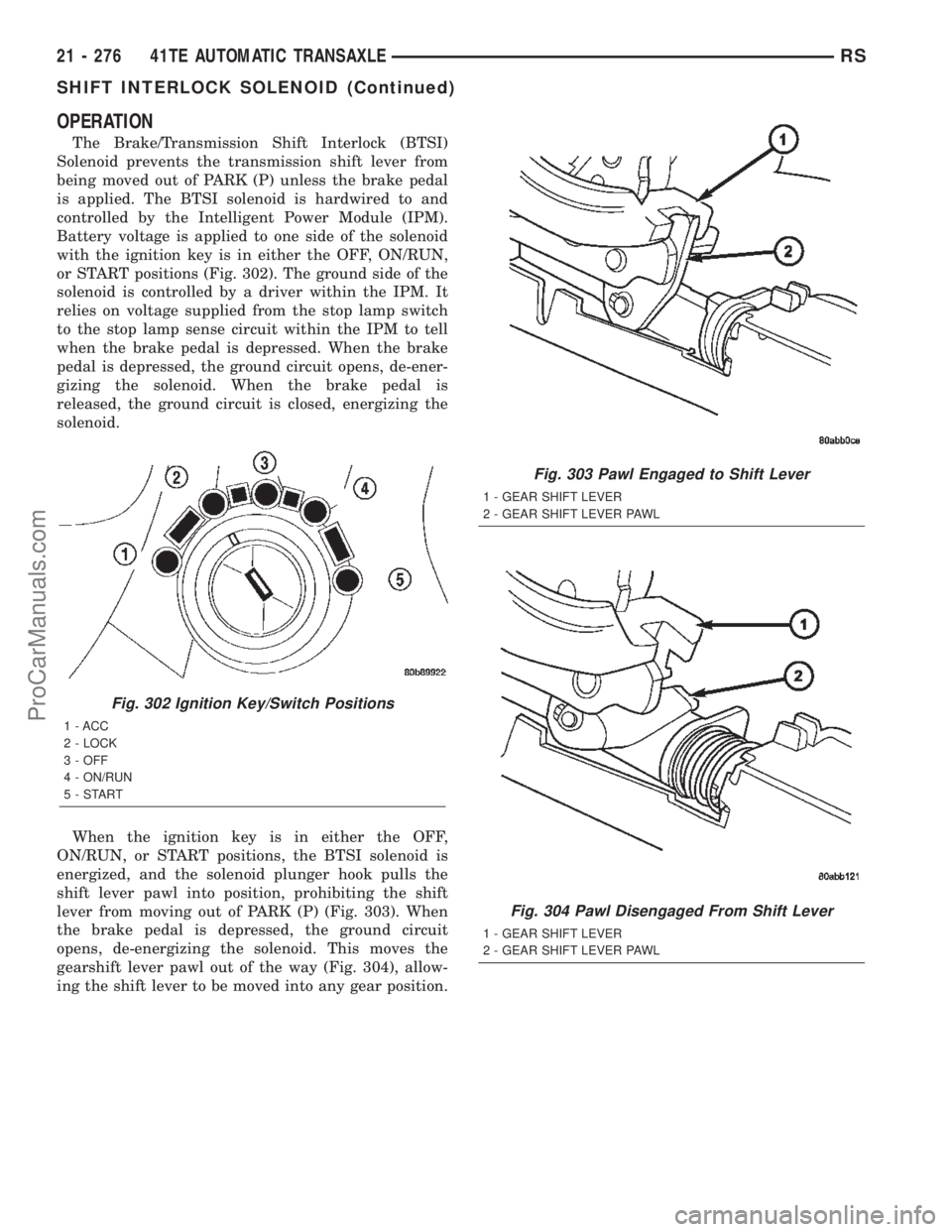
or START positions (Fig. 302). The ground side of the
solenoid is controlled by a driver within the IPM. It
relies on voltage supplied from the stop lamp switch
to the stop lamp sense circuit within the IPM to tell
when the brake pedal is depressed. When the brake
pedal is depressed, the ground circuit opens, de-ener-
gizing the solenoid. When the brake pedal is
released, the ground circuit is closed, energizing the
solenoid.
When the ignition key is in either the OFF,
ON/RUN, or START positions, the BTSI solenoid is
energized, and the solenoid plunger hook pulls the
shift lever pawl into position, prohibiting the shift
lever from moving out of PARK (P) (Fig. 303). When
the brake pedal is depressed, the ground circuit
opens, de-energizing the solenoid. This moves the
gearshift lever pawl out of the way (Fig. 304), allow-
ing the shift lever to be moved into any gear position.
Fig. 302 Ignition Key/Switch Positions
1 - ACC
2 - LOCK
3 - OFF
4 - ON/RUN
5-START
Fig. 303 Pawl Engaged to Shift Lever
1 - GEAR SHIFT LEVER
2 - GEAR SHIFT LEVER PAWL
Fig. 304 Pawl Disengaged From Shift Lever
1 - GEAR SHIFT LEVER
2 - GEAR SHIFT LEVER PAWL
21 - 276 41TE AUTOMATIC TRANSAXLERS
SHIFT INTERLOCK SOLENOID (Continued)
ProCarManuals.com
Page 1834 of 2399
A conventional mechanical interlock system is also
used. This system manually prohibits shifter move-
ment when the ignition switch is in the LOCK or
ACC positions. Solenoid operation is not required in
these key positions.
For intended BTSI system operation, refer to the
following chart:
ACTION EXPECTED RESPONSE
1. Turn key to the9OFF9
position.1. Shifter CAN be shifted
out of park with brake
pedal applied.
2. Turn key to the
9ON/RUN9position.2. Shifter CANNOT be
shifted out of park.
3. Turn key to the
9ON/RUN9position and
depress the brake pedal.3. Shifter CAN be shifted
out of park.
4. Leave shifter in any
gear and try to return key
to the9LOCK9or9ACC9
position.4. Key cannot be
returned to the9LOCK9or
9ACC9position.
5. Return shifter to
9PARK9and try to remove
the key.5. Key can be removed
(after returning to9LOCK9
position).
6. With the key removed,
try to shift out of9PARK9.6. Shifter cannot be
shifted out of9PARK9.
NOTE: Any failure to meet these expected
responses requires system adjustment or repair.
DIAGNOSIS AND TESTING - BRAKE/
TRANSMISSION SHIFT INTERLOCK SOLENOID
For intended BTSI system operation, refer to the
following chart:
ACTION EXPECTED RESPONSE
1. Turn key to the9OFF9
position.1. Shifter CAN be shifted
out of park with brake
pedal applied.
2. Turn key to the
9ON/RUN9position.2. Shifter CANNOT be
shifted out of park.
3. Turn key to the
9ON/RUN9position and
depress the brake pedal.3. Shifter CAN be shifted
out of park.
4. Leave shifter in any
gear and try to return key
to the9LOCK9or9ACC9
position.4. Key cannot be
returned to the9LOCK9or
9ACC9position.
5. Return shifter to
9PARK9and try to remove
the key.5. Key can be removed
(after returning to9LOCK9
position).
ACTION EXPECTED RESPONSE
6. With the key removed,
try to shift out of9PARK9.6. Shifter cannot be
shifted out of9PARK9.
NOTE: Any failure to meet these expected
responses requires system repair. Refer to the
appropriate Diagnostic Information.
REMOVAL
(1) Disconnect battery negative cable.
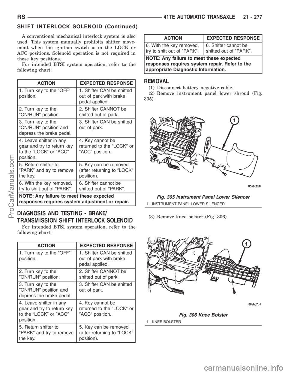
(2) Remove instrument panel lower shroud (Fig.
305).
(3) Remove knee bolster (Fig. 306).
Fig. 305 Instrument Panel Lower Silencer
1 - INSTRUMENT PANEL LOWER SILENCER
Fig. 306 Knee Bolster
1 - KNEE BOLSTER
RS41TE AUTOMATIC TRANSAXLE21 - 277
SHIFT INTERLOCK SOLENOID (Continued)
ProCarManuals.com
Page 1835 of 2399
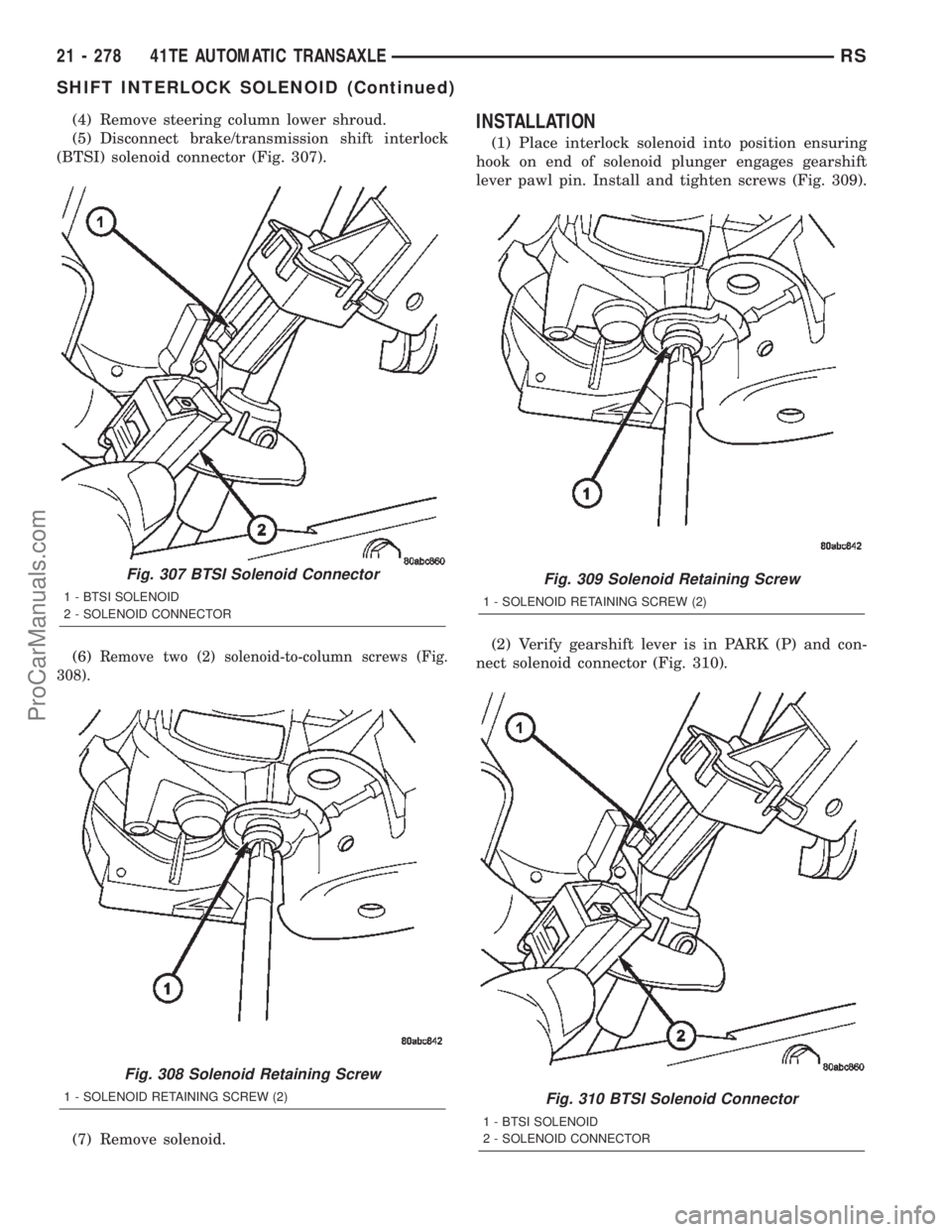
(4) Remove steering column lower shroud.
(5) Disconnect brake/transmission shift interlock
(BTSI) solenoid connector (Fig. 307).
(6)
Remove two (2) solenoid-to-column screws (Fig.
308).
(7) Remove solenoid.
INSTALLATION
(1) Place interlock solenoid into position ensuring
hook on end of solenoid plunger engages gearshift
lever pawl pin. Install and tighten screws (Fig. 309).
(2) Verify gearshift lever is in PARK (P) and con-
nect solenoid connector (Fig. 310).
Fig. 307 BTSI Solenoid Connector
1 - BTSI SOLENOID
2 - SOLENOID CONNECTOR
Fig. 308 Solenoid Retaining Screw
1 - SOLENOID RETAINING SCREW (2)
Fig. 309 Solenoid Retaining Screw
1 - SOLENOID RETAINING SCREW (2)
Fig. 310 BTSI Solenoid Connector
1 - BTSI SOLENOID
2 - SOLENOID CONNECTOR
21 - 278 41TE AUTOMATIC TRANSAXLERS
SHIFT INTERLOCK SOLENOID (Continued)
ProCarManuals.com
Page 1836 of 2399
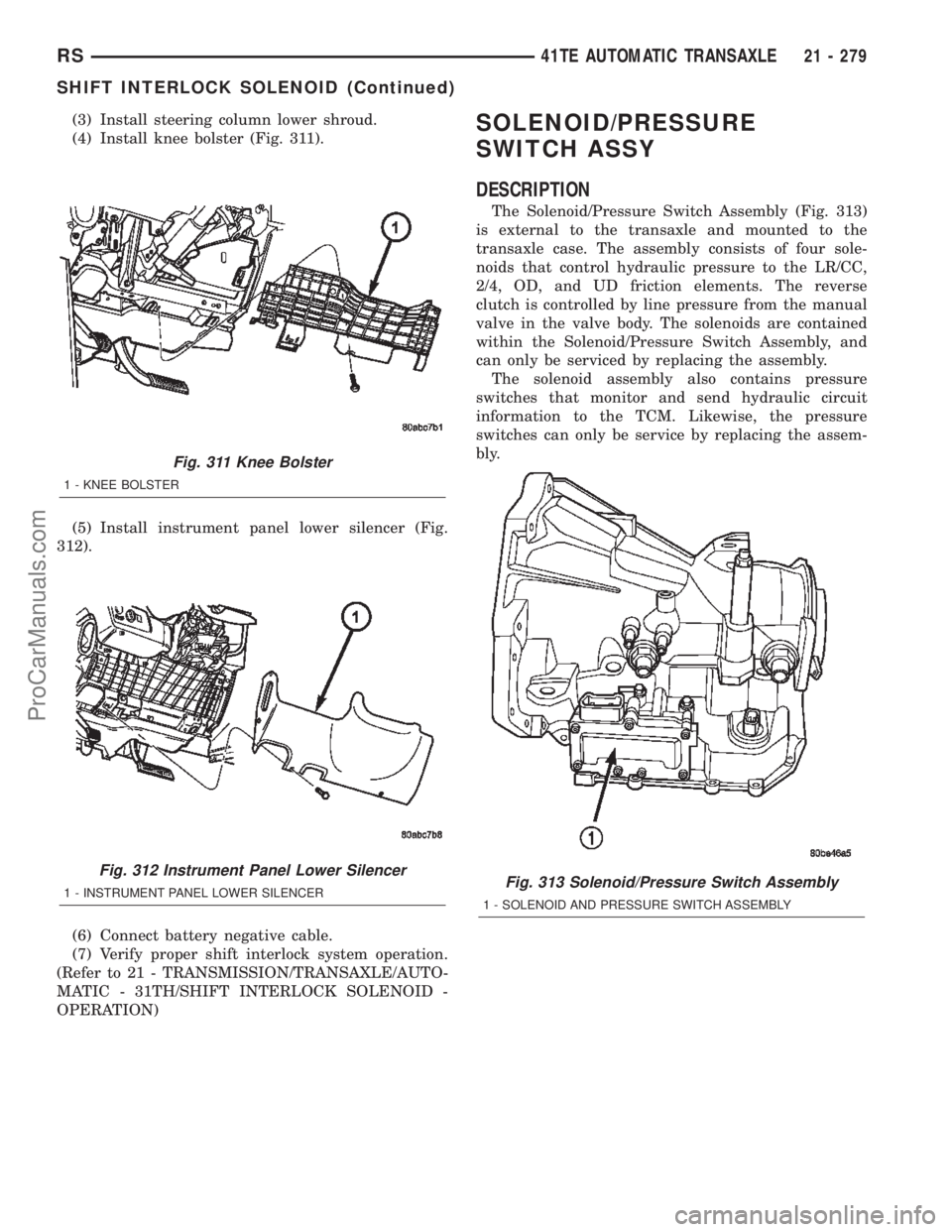
(3) Install steering column lower shroud.
(4) Install knee bolster (Fig. 311).
(5) Install instrument panel lower silencer (Fig.
312).
(6) Connect battery negative cable.
(7) Verify proper shift interlock system operation.
(Refer to 21 - TRANSMISSION/TRANSAXLE/AUTO-
MATIC - 31TH/SHIFT INTERLOCK SOLENOID -
OPERATION)SOLENOID/PRESSURE
SWITCH ASSY
DESCRIPTION
The Solenoid/Pressure Switch Assembly (Fig. 313)
is external to the transaxle and mounted to the
transaxle case. The assembly consists of four sole-
noids that control hydraulic pressure to the LR/CC,
2/4, OD, and UD friction elements. The reverse
clutch is controlled by line pressure from the manual
valve in the valve body. The solenoids are contained
within the Solenoid/Pressure Switch Assembly, and
can only be serviced by replacing the assembly.
The solenoid assembly also contains pressure
switches that monitor and send hydraulic circuit
information to the TCM. Likewise, the pressure
switches can only be service by replacing the assem-
bly.
Fig. 311 Knee Bolster
1 - KNEE BOLSTER
Fig. 312 Instrument Panel Lower Silencer
1 - INSTRUMENT PANEL LOWER SILENCERFig. 313 Solenoid/Pressure Switch Assembly
1 - SOLENOID AND PRESSURE SWITCH ASSEMBLY
RS41TE AUTOMATIC TRANSAXLE21 - 279
SHIFT INTERLOCK SOLENOID (Continued)
ProCarManuals.com
Page 1837 of 2399
OPERATION
SOLENOIDS
The solenoids receive electrical power from the
Transmission Control Relay through a single wire.
The TCM energizes or operates the solenoids individ-
ually by grounding the return wire of the solenoid
needed. When a solenoid is energized, the solenoid
valve shifts, and a fluid passage is opened or closed
(vented or applied), depending on its default operat-
ing state. The result is an apply or release of a fric-
tional element.
The 2/4 and UD solenoids are normally applied,
which by design allow fluid to pass through in their
relaxed or ªoffº state. This allows transaxle limp-in
(P,R,N,2) in the event of an electrical failure.
The continuity of the solenoids and circuits are
periodically tested. Each solenoid is turned on or off
depending on its current state. An inductive spike
should be detected by the TCM during this test. It no
spike is detected, the circuit is tested again to verify
the failure. In addition to the periodic testing, the
solenoid circuits are tested if a speed ratio or pres-
sure switch error occurs.
PRESSURE SWITCHES
The TCM relies on three pressure switches to mon-
itor fluid pressure in the L/R, 2/4, and OD hydraulic
circuits. The primary purpose of these switches is to
help the TCM detect when clutch circuit hydraulic
failures occur. The range for the pressure switch clos-
ing and opening points is 11-23 psi. Typically the
switch opening point will be approximately one psi
lower than the closing point. For example, a switch
may close at 18 psi and open at 17 psi. The switches
are continuously monitored by the TCM for the cor-
rect states (open or closed) in each gear as shown in
the following chart:
PRESSURE SWITCH STATES
GEAR L/R 2/4 OD
ROPOPOP
P/N CL OP OP
1st CL OP OP
2nd OP CL OP
DOPOPCL
OD OP CL CL
OP = OPEN
CL = CLOSED
A Diagnostic Trouble Code (DTC) will set if the
TCM senses any switch open or closed at the wrong
time in a given gear.The TCM also tests the 2/4 and OD pressure
switches when they are normally off (OD and 2/4 are
tested in 1st gear, OD in 2nd gear, and 2/4 in 3rd
gear). The test simply verifies that they are opera-
tional, by looking for a closed state when the corre-
sponding element is applied. Immediately after a
shift into 1st, 2nd, or 3rd gear with the engine speed
above 1000 rpm, the TCM momentarily turns on ele-
ment pressure to the 2/4 and/or OD clutch circuits to
identify that the appropriate switch has closed. If it
doesn't close, it is tested again. If the switch fails to
close the second time, the appropriate Diagnostic
Trouble Code (DTC) will set.
REMOVAL
NOTE: If solenoid/pressure switch assembly is
being replaced, it is necessary to perform the TCM
Quick Learn Procedure. (Refer to 8 - ELECTRICAL/
ELECTRONIC CONTROL MODULES/TRANSMISSION
CONTROL MODULE - STANDARD PROCEDURE)
(1) Disconnect battery negative cable.
(2) Remove air cleaner assembly.
(3) Disconnect solenoid/pressure switch assembly
connector.
(4) Disconnect input speed sensor connector.
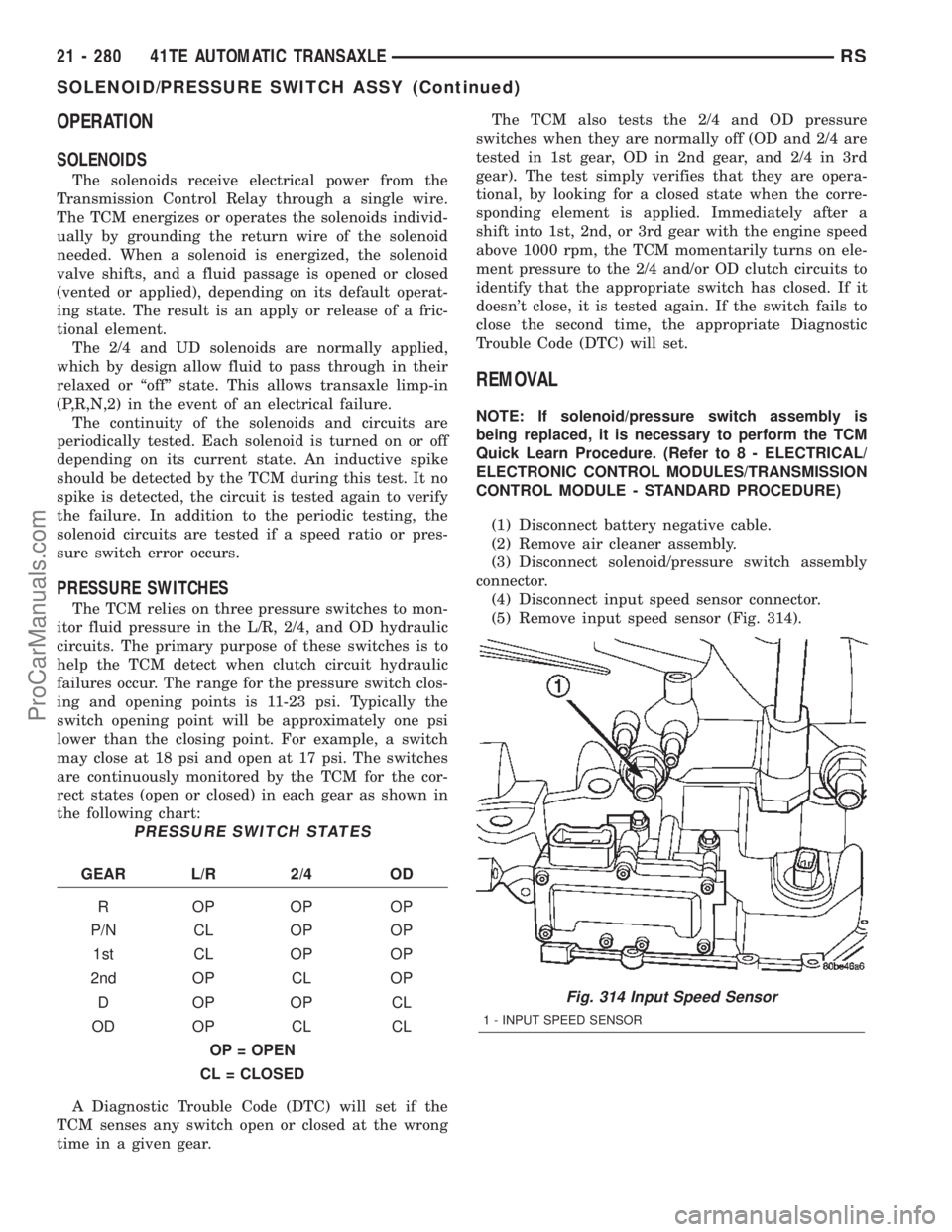
(5) Remove input speed sensor (Fig. 314).
Fig. 314 Input Speed Sensor
1 - INPUT SPEED SENSOR
21 - 280 41TE AUTOMATIC TRANSAXLERS
SOLENOID/PRESSURE SWITCH ASSY (Continued)
ProCarManuals.com
Page 1838 of 2399
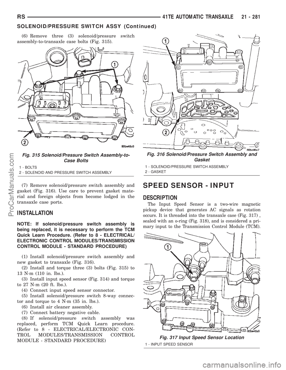
(6) Remove three (3) solenoid/pressure switch
assembly-to-transaxle case bolts (Fig. 315).
(7) Remove solenoid/pressure switch assembly and
gasket (Fig. 316). Use care to prevent gasket mate-
rial and foreign objects from become lodged in the
transaxle case ports.
INSTALLATION
NOTE: If solenoid/pressure switch assembly is
being replaced, it is necessary to perform the TCM
Quick Learn Procedure. (Refer to 8 - ELECTRICAL/
ELECTRONIC CONTROL MODULES/TRANSMISSION
CONTROL MODULE - STANDARD PROCEDURE)
(1) Install solenoid/pressure switch assembly and
new gasket to transaxle (Fig. 316).
(2) Install and torque three (3) bolts (Fig. 315) to
13 N´m (110 in. lbs.).
(3) Install input speed sensor (Fig. 314) and torque
to 27 N´m (20 ft. lbs.).
(4) Connect input speed sensor connector.
(5) Install solenoid/pressure switch 8-way connec-
tor and torque to 4 N´m (35 in. lbs.).
(6) Install air cleaner assembly.
(7) Connect battery negative cable.
(8) If solenoid/pressure switch assembly was
replaced, perform TCM Quick Learn procedure.
(Refer to 8 - ELECTRICAL/ELECTRONIC CON-
TROL MODULES/TRANSMISSION CONTROL
MODULE - STANDARD PROCEDURE)
SPEED SENSOR - INPUT
DESCRIPTION
The Input Speed Sensor is a two-wire magnetic
pickup device that generates AC signals as rotation
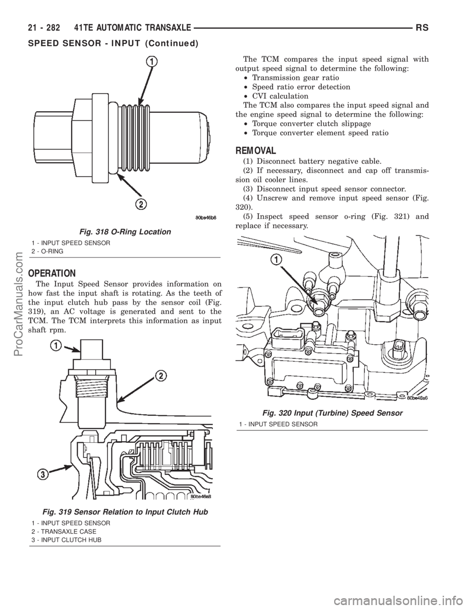
occurs. It is threaded into the transaxle case (Fig. 317) ,
sealed with an o-ring (Fig. 318), and is considered a pri-
mary input to the Transmission Control Module (TCM).
Fig. 315 Solenoid/Pressure Switch Assembly-to-
Case Bolts
1 - BOLTS
2 - SOLENOID AND PRESSURE SWITCH ASSEMBLY
Fig. 316 Solenoid/Pressure Switch Assembly and
Gasket
1 - SOLENOID/PRESSURE SWITCH ASSEMBLY
2 - GASKET
Fig. 317 Input Speed Sensor Location
1 - INPUT SPEED SENSOR
RS41TE AUTOMATIC TRANSAXLE21 - 281
SOLENOID/PRESSURE SWITCH ASSY (Continued)
ProCarManuals.com
Page 1839 of 2399
OPERATION
The Input Speed Sensor provides information on
how fast the input shaft is rotating. As the teeth of
the input clutch hub pass by the sensor coil (Fig.
319), an AC voltage is generated and sent to the
TCM. The TCM interprets this information as input
shaft rpm.The TCM compares the input speed signal with
output speed signal to determine the following:
²Transmission gear ratio
²Speed ratio error detection
²CVI calculation
The TCM also compares the input speed signal and
the engine speed signal to determine the following:
²Torque converter clutch slippage
²Torque converter element speed ratio
REMOVAL
(1) Disconnect battery negative cable.
(2) If necessary, disconnect and cap off transmis-
sion oil cooler lines.
(3) Disconnect input speed sensor connector.
(4) Unscrew and remove input speed sensor (Fig.
320).
(5) Inspect speed sensor o-ring (Fig. 321) and
replace if necessary.
Fig. 318 O-Ring Location
1 - INPUT SPEED SENSOR
2 - O-RING
Fig. 319 Sensor Relation to Input Clutch Hub
1 - INPUT SPEED SENSOR
2 - TRANSAXLE CASE
3 - INPUT CLUTCH HUB
Fig. 320 Input (Turbine) Speed Sensor
1 - INPUT SPEED SENSOR
21 - 282 41TE AUTOMATIC TRANSAXLERS
SPEED SENSOR - INPUT (Continued)
ProCarManuals.com
Page 1840 of 2399
INSTALLATION
(1) Verify o-ring is installed into position.
(2) Install and tighten input speed sensor to 27
N´m (20 ft. lbs.).
(3) Connect speed sensor connector.
(4) Connect battery negative cable.
SPEED SENSOR - OUTPUT
DESCRIPTION
The Output Speed Sensor is a two-wire magnetic
pickup device that generates an AC signal as rotation
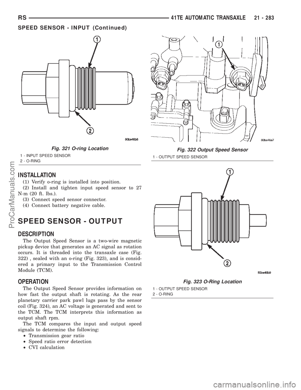
occurs. It is threaded into the transaxle case (Fig.
322) , sealed with an o-ring (Fig. 323), and is consid-
ered a primary input to the Transmission Control
Module (TCM).
OPERATION
The Output Speed Sensor provides information on
how fast the output shaft is rotating. As the rear
planetary carrier park pawl lugs pass by the sensor
coil (Fig. 324), an AC voltage is generated and sent to
the TCM. The TCM interprets this information as
output shaft rpm.
The TCM compares the input and output speed
signals to determine the following:
²Transmission gear ratio
²Speed ratio error detection
²CVI calculation
Fig. 321 O-ring Location
1 - INPUT SPEED SENSOR
2 - O-RING
Fig. 322 Output Speed Sensor
1 - OUTPUT SPEED SENSOR
Fig. 323 O-Ring Location
1 - OUTPUT SPEED SENSOR
2 - O-RING
RS41TE AUTOMATIC TRANSAXLE21 - 283
SPEED SENSOR - INPUT (Continued)
ProCarManuals.com