Vtss CHRYSLER VOYAGER 2002 User Guide
[x] Cancel search | Manufacturer: CHRYSLER, Model Year: 2002, Model line: VOYAGER, Model: CHRYSLER VOYAGER 2002Pages: 2399, PDF Size: 57.96 MB
Page 2002 of 2399

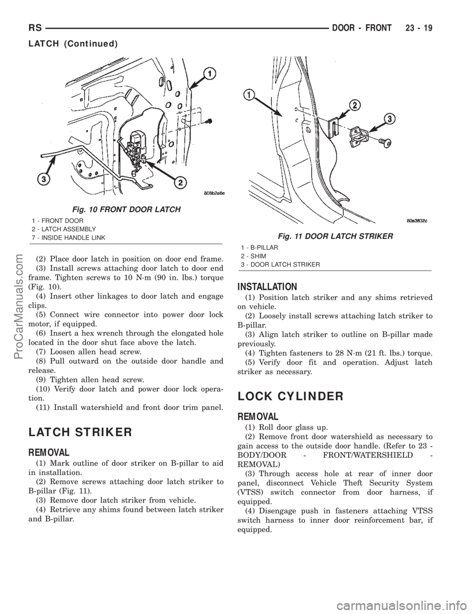
(2) Place door latch in position on door end frame.
(3) Install screws attaching door latch to door end
frame. Tighten screws to 10 N´m (90 in. lbs.) torque
(Fig. 10).
(4) Insert other linkages to door latch and engage
clips.
(5) Connect wire connector into power door lock
motor, if equipped.
(6) Insert a hex wrench through the elongated hole
located in the door shut face above the latch.
(7) Loosen allen head screw.
(8) Pull outward on the outside door handle and
release.
(9) Tighten allen head screw.
(10) Verify door latch and power door lock opera-
tion.
(11) Install watershield and front door trim panel.
LATCH STRIKER
REMOVAL
(1) Mark outline of door striker on B-pillar to aid
in installation.
(2) Remove screws attaching door latch striker to
B-pillar (Fig. 11).
(3) Remove door latch striker from vehicle.
(4) Retrieve any shims found between latch striker
and B-pillar.
INSTALLATION
(1) Position latch striker and any shims retrieved
on vehicle.
(2) Loosely install screws attaching latch striker to
B-pillar.
(3) Align latch striker to outline on B-pillar made
previously.
(4) Tighten fasteners to 28 N´m (21 ft. lbs.) torque.
(5) Verify door fit and operation. Adjust latch
striker as necessary.
LOCK CYLINDER
REMOVAL
(1) Roll door glass up.
(2) Remove front door watershield as necessary to
gain access to the outside door handle. (Refer to 23 -
BODY/DOOR - FRONT/WATERSHIELD -
REMOVAL)
(3) Through access hole at rear of inner door
panel, disconnect Vehicle Theft Security System
(VTSS) switch connector from door harness, if
equipped.
(4) Disengage push in fasteners attaching VTSS
switch harness to inner door reinforcement bar, if
equipped.
Fig. 10 FRONT DOOR LATCH
1 - FRONT DOOR
2 - LATCH ASSEMBLY
7 - INSIDE HANDLE LINK
Fig. 11 DOOR LATCH STRIKER
1 - B-PILLAR
2 - SHIM
3 - DOOR LATCH STRIKER
RSDOOR - FRONT23-19
LATCH (Continued)
ProCarManuals.com
Page 2003 of 2399

(5) Disengage clip holding door latch linkage to
door latch (Fig. 12).
(6) Remove latch linkage from latch.
(7) Disengage clip holding door lock linkage to
door latch.
(8) Remove lock linkage from latch.
(9) Remove nuts attaching outside door handle to
door outer panel.
(10) Remove outside door handle from vehicle.
(11) Disengage clip holding lock cylinder into out-
side handle.
(12) Pull lock cylinder from door handle.
INSTALLATION
(1) Engage clip into outside handle to hold lock
cylinder (Fig. 12).
(2) With link arm toward rear of vehicle, push lock
cylinder into door handle until clip snaps into place.
(3) Insert lock linkage into door latch.
(4) Engage clip to hold door lock linkage to latch.
(5) Insert latch linkage into door latch.
(6) Engage clip to hold door latch linkage to latch.
(7) Install push in fasteners attaching VTSS
switch harness to inner door reinforcement bar, if
equipped.
(8) Connect VTSS switch connector into door har-
ness, if equipped.
(9) Verify door latch operation.(10) Install watershield and door trim panel.
TRIM PANEL
REMOVAL
(1) Remove the plug and remove screw attaching
door pull cup to inner door panel.
(2) Remove switch bezel and disconnect power win-
dow/memory switch.
(3) Remove screws attaching trim panel to door
from below map pocket.
(4) If equipped, remove window crank. (Refer to 23
- BODY/DOOR - FRONT/WINDOW CRANK -
REMOVAL)
(5) Remove screw holding door trim to door panel
from behind inside latch release handle.
(6) Disengage clips attaching door trim to door
frame around perimeter of panel.
(7) Lift trim panel upward to disengage flange
from inner belt molding at top of door.
(8) Tilt top of trim panel away from door to gain
access to latch linkage.
(9) Disengage clip attaching linkage rod to inside
latch release handle (Fig. 13).
(10) Separate linkage rod from latch handle.
(11) Disconnect the power door switch, courtesy
lamp electrical connectors.
Fig. 12 OUTSIDE DOOR HANDLE
1 - CLIP
2 - LOCK CYLINDER
3 - KEY CYLINDER TO LATCH LINK
4 - OUTSIDE HANDLE TO LATCH LINK
5 - LOCK KNOB LINK6 - FRONT DOOR
7 - KEY POSITION SWITCH
8 - OUTSIDE HANDLE
23 - 20 DOOR - FRONTRS
LOCK CYLINDER (Continued)
ProCarManuals.com
Page 2006 of 2399

EXTERIOR HANDLE
REMOVAL
(1) Roll door glass up.
(2) Remove the watershield. (Refer to 23 - BODY/
DOOR - FRONT/WATERSHIELD - REMOVAL)
(3) Through access hole at rear of inner door
panel, disconnect Vehicle Theft Security System
(VTSS) switch connector from door harness, if
equipped.
(4) Disengage push in fasteners attaching VTSS
switch harness to inner door reinforcement bar, if
equipped.
(5) Disengage clip holding door latch linkage to
door latch (Fig. 12).
(6) Remove latch linkage from latch.
(7) Disengage clip holding door lock linkage to
door latch.
(8) Remove lock linkage from latch.
(9) Remove nuts holding outside door handle to
door outer panel.(10) Remove outside door handle from vehicle.
INSTALLATION
If outside door handle replacement is necessary,
transfer lock cylinder from the original handle to the
new one.
(1) Place outside door handle in position on vehi-
cle.
(2) Install nuts attaching outside door handle to
door outer panel (Fig. 12). Tighten nuts to 6 N´m (50
in. lbs.).
(3) Insert lock linkage into door latch.
(4) Engage clip to hold door lock linkage to latch.
(5) Insert latch linkage into door latch.
(6) Engage clip to hold door latch linkage to latch.
(7) Install push-in fasteners to hold VTSS switch
harness to inner door reinforcement bar, if equipped.
(8) Connect VTSS switch connector into door har-
ness, if equipped.
(9) Verify door latch operation.
(10) Install sound shield and door trim panel.
RSDOOR - FRONT23-23
ProCarManuals.com
Page 2022 of 2399

DECKLID/HATCH/LIFTGATE/TAILGATE
TABLE OF CONTENTS
page page
EXTERIOR HANDLE
REMOVAL.............................39
INSTALLATION.........................39
HINGE
REMOVAL.............................39
INSTALLATION.........................39
LATCH
REMOVAL.............................40
INSTALLATION.........................40
LATCH STRIKER
REMOVAL.............................40
INSTALLATION.........................40
LIFTGATE
REMOVAL.............................40
INSTALLATION.........................41
LIFTGATE SPOILER
REMOVAL.............................41INSTALLATION.........................41
LOCK CYLINDER
REMOVAL.............................42
INSTALLATION.........................42
SUPPORT CYLINDER
REMOVAL.............................42
INSTALLATION.........................42
TRIM PANEL
REMOVAL.............................42
INSTALLATION.........................43
SLAM BUMPER
REMOVAL
REMOVAL...........................43
REMOVAL - LIFTGATE SIDE.............43
INSTALLATION
INSTALLATION.......................43
INSTALLATION - LIFTGATE SIDE.........43
EXTERIOR HANDLE
REMOVAL
(1) Remove liftgate trim panel. (Refer to 23 -
BODY/DECKLID/HATCH/LIFTGATE/TAILGATE/
TRIM PANEL - REMOVAL)
(2) Disconnect the exterior handle electrical con-
nectors.
(3) Remove the two outer screws and the two inner
screws.
(4) Remove the exterior handle/license plate light
assembly.
INSTALLATION
(1) Route the exterior handle electrical connector
through the door and position handle.
(2) Install the two out screws and tighten to 20
N´m (15 ft. lbs.).
(3) Install the two inner bolts and tighten to 40
N´m (30 ft. lbs.).
(4) Connect the electrical connector.
(5) Install the trim panel. (Refer to 23 - BODY/
DECKLID/HATCH/LIFTGATE/TAILGATE/TRIM
PANEL - INSTALLATION)
HINGE
REMOVAL
(1) Release liftgate latch and open liftgate.
(2) Support liftgate on a suitable lifting device in
the full open position.
(3) Apply several layers of duct tape on the outside
of to roof across the gap to the lift gate to hold the
liftgate in position.
(4) Remove bolts attaching liftgate hinge to roof
header.
(5) Disconnect VTSS switch from the body har-
ness.
(6) Remove bolts attaching hinge to liftgate (Fig.
1).
(7) Remove hinge from vehicle.
INSTALLATION
(1) If necessary, paint replacement hinge before
installation.
(2) Place hinge in position on vehicle.
(3) Align hinge to marks on liftgate.
(4) Install bolts attaching hinge to liftgate (Fig. 1)
. Tighten bolts to 33 N´m (24 ft. lbs.) torque.
RSDECKLID/HATCH/LIFTGATE/TAILGATE23-39
ProCarManuals.com