diagram CHRYSLER VOYAGER 2002 User Guide
[x] Cancel search | Manufacturer: CHRYSLER, Model Year: 2002, Model line: VOYAGER, Model: CHRYSLER VOYAGER 2002Pages: 2399, PDF Size: 57.96 MB
Page 330 of 2399
REMOTE SWITCHES
DESCRIPTION
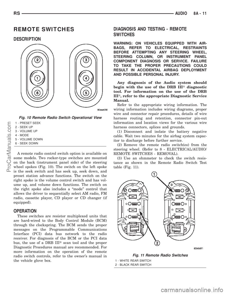
A remote radio control switch option is available on
some models. Two rocker-type switches are mounted
on the back (instrument panel side) of the steering
wheel spokes (Fig. 10). The switch on the left spoke
is the seek switch and has seek up, seek down, and
preset station advance functions. The switch on the
right spoke is the volume control switch and has vol-
ume up, and volume down functions. The switch on
the right spoke also includes a ªmodeº control that
allows the driver to sequentially select AM radio, FM
radio, cassette player, CD player or CD changer (if
equipped).
OPERATION
These switches are resistor multiplexed units that
are hard-wired to the Body Control Module (BCM)
through the clockspring. The BCM sends the proper
messages on the Programmable Communications
Interface (PCI) data bus network to the radio
receiver. For diagnosis of the BCM or the PCI data
bus, the use of a DRB IIItscan tool and the proper
Diagnostic Procedures manual are recommended. For
more information on the operation of the remote
radio switch controls, refer to the owner's manual in
the vehicle glove box.
DIAGNOSIS AND TESTING - REMOTE
SWITCHES
WARNING: ON VEHICLES EQUIPPED WITH AIR-
BAGS, REFER TO ELECTRICAL, RESTRAINTS
BEFORE ATTEMPTING ANY STEERING WHEEL,
STEERING COLUMN, OR INSTRUMENT PANEL
COMPONENT DIAGNOSIS OR SERVICE. FAILURE
TO TAKE THE PROPER PRECAUTIONS COULD
RESULT IN ACCIDENTAL AIRBAG DEPLOYMENT
AND POSSIBLE PERSONAL INJURY.
Any diagnosis of the Audio system should
begin with the use of the DRB IIItdiagnostic
tool. For information on the use of the DRB
IIIt, refer to the appropriate Diagnostic Service
Manual.
Refer to the appropriate wiring information. The
wiring information includes wiring diagrams, proper
wire and connector repair procedures, details of wire
harness routing and retention, connector pin-out
information and location views for the various wire
harness connectors, splices and grounds.
(1) Disconnect and isolate the battery negative
cable. Wait two minutes for the airbag system capac-
itor to discharge before further service.
(2) Remove the remote radio switch(es) from the
steering wheel. (Refer to 8 - ELECTRICAL/AUDIO/
REMOTE SWITCHES - REMOVAL).
(3) Use an ohmmeter to check the switch resis-
tance as shown in the Remote Radio Switch Test
table (Fig. 11).
Fig. 10 Remote Radio Switch Operational View
1 - PRESET SEEK
2 - SEEK UP
3 - VOLUME UP
4 - MODE
5 - VOLUME DOWN
6 - SEEK DOWN
Fig. 11 Remote Radio Switches
1 - WHITE REAR SWITCH
2 - BLACK REAR SWITCH
RSAUDIO8A-11
ProCarManuals.com
Page 332 of 2399
Any diagnosis of the Audio system should
begin with the use of the DRB IIItdiagnostic
tool. For information on the use of the DRB
IIIt, refer to the appropriate Diagnostic Service
Manual.
Refer to the appropriate wiring information. The
wiring information includes wiring diagrams, proper
wire and connector repair procedures, details of wire
harness routing and retention, connector pin-out
information and location views for the various wire
harness connectors, splices and grounds.
CAUTION: The speaker output of the radio is a
ªfloating groundº system. Do not allow any speaker
lead to short to ground, as damage to the radio
may result.
(1) If all speakers are inoperative, check the radio
fuses in the junction block. If OK, go to Step 2. If not
OK, repair the shorted circuit or component as
required and replace the faulty fuse.
(2) Turn the ignition switch to the ON position.
Turn the radio receiver ON. Adjust the balance and
fader control controls to check the performance of
each individual speaker. Note the speaker locations
that are not performing correctly. Go to Step 3.
(3) Turn the radio receiver OFF. Turn the ignition
OFF. Disconnect and isolate the battery negative
cable. Remove the radio receiver.
(4) Check both the speaker feed (+) circuit and
return (-) circuit cavities for the inoperative speaker
at the radio receiver wire harness connector for con-
tinuity to ground. There should be no continuity. If
OK, go to Step 5. If not OK, repair the shorted
speaker feed (+) and/or return (-) circuits(s) to the
speaker as required.
(5) Disconnect wire harness connector at the inop-
erative speaker. Check for continuity between the
speaker feed (+) circuit cavities of the radio receiver
wire harness connector. Repeat the check between
the speaker return (-) circuit cavities of the radio
receiver wire harness connector and the speaker wire
harness connector. In each case, there should be con-
tinuity. If OK, replace the faulty speaker. If not OK,
repair the open speaker feed (+) and/or return (-) cir-
cuits(s) as required.
REMOVAL
D-PILLAR SPEAKER
(1)Disconnect and isolate the battery negative cable.
(2) Remove rear header trim (right side speaker).
(3) Remove jack cover (left side speaker).
(4) Remove liftgate scuff plate.
(5) Remove upper seat belt bolt. (Refer to 8 -
ELECTRICAL/RESTRAINTS/SEAT BELT OUT-
BOARD FRONT - REMOVAL).(6) Partially remove quarter trim panel to access
the D-pillar speaker.
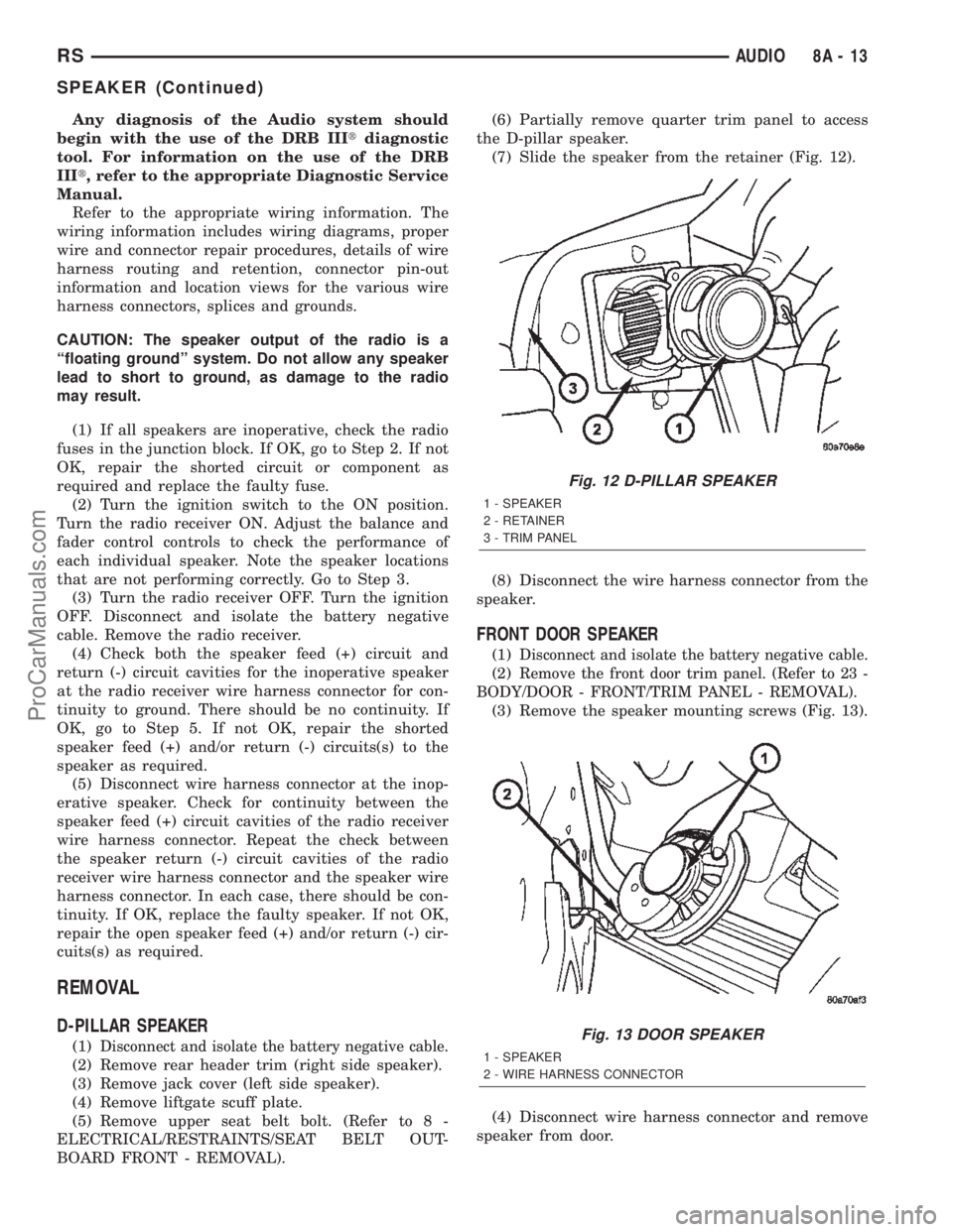
(7) Slide the speaker from the retainer (Fig. 12).
(8) Disconnect the wire harness connector from the
speaker.
FRONT DOOR SPEAKER
(1)Disconnect and isolate the battery negative cable.
(2)Remove the front door trim panel. (Refer to 23 -
BODY/DOOR - FRONT/TRIM PANEL - REMOVAL).
(3) Remove the speaker mounting screws (Fig. 13).
(4) Disconnect wire harness connector and remove
speaker from door.
Fig. 12 D-PILLAR SPEAKER
1 - SPEAKER
2 - RETAINER
3 - TRIM PANEL
Fig. 13 DOOR SPEAKER
1 - SPEAKER
2 - WIRE HARNESS CONNECTOR
RSAUDIO8A-13
SPEAKER (Continued)
ProCarManuals.com
Page 335 of 2399
(a) BCM has two battery feeds at pin 1 and pin
5 of the 6±way connector.
(b) Pin 5 of the (BX2) 32 way connector of the
BCM for ignition feed.
(c) Check voltage (PX2) connector, pin 34 for 12v.
(d) If voltage OK, go to step Step 3
(e) If NO voltage repair as necessary. Refer to
the appropriate wiring information. The wiring
information includes wiring diagrams, proper wire
and connector repair procedures, further details on
wire harness routing and retention, as well as pin-
out and location views for the various wire harness
connectors, splices and grounds.
(3) Check driver's seat belt buckle switch input
(form ORC) for a closed circuit when not buckled. If
input not seen, look for open in wiring or switch. The
switch is grounded when belt is not buckled.
(4) Verify PCI data bus communication between
ORC and BCM.
NO FASTEN SEAT BELT LAMP WHEN IGNITION
SWITCH IS TURNED ON.
(1) Check for burned out lamp.
(2) Using a voltmeter check for voltage at the clus-
ter conncctor:
(a) Pin 2 of the mechanical instrument cluster
for battery feed.
(b) Pin 11 of the mechanical instrument cluster
for ignition voltage.
(3) Repair as necessary.
FASTEN SEAT BELT LAMP OR TONE CONTINUES
FOR MORE THAN 10 SECONDS AFTER SEAT
BELTS ARE FASTENED AND DRIVER'S DOOR IS
CLOSED.
Refer to the proper Body Diagnostic Procedures
manual.
NO TONE WHEN PARK OR HEADLAMPS ARE ON
AND DRIVER'S DOOR IS OPEN.
Make sure ignition is in lock position with the key
removed.
(1) Check the BCM DTC's and BCM sensors to
verify the door is open. Repair as necessary.
(2) Actuate Chime (BCM actuates).
(3) Inspect BCM connectors and wires for proper
connection.
(4) Measure with a voltmeter the voltage (12v) on
BCM connector (PX2) pin 34 with harness connected.
DIAGNOSIS AND TESTING - DOME LAMP ON
CHIME
The dome lamp on chime will warn the driver that
the dome lamps have been left on.When the ignition is OFF and the key is out of the
ignition:
²Driver's door OPEN (door ajar switch is closed to
ground) and
²Dome lamps are ON (dome lamp switch is closed
to ground),
The chime will sound continuously until the driv-
ers door is closed, dome lamps turned OFF or until
the battery protection time out of 15 minutes has
expired. Chime rate: 168 to 192 chimes per minute.
DIAGNOSIS AND TESTING - ENGINE
TEMPERATURE CRITICAL CHIME
The engine temperature critical chime will warn
the driver that the vehicle's engine is overheating.
While monitoring the coolant temperature, the Pow-
ertrain Control Module (PCM) will send on the PCI
data bus as engine temperature every 1.376 seconds
to the cluster. The MIC calculates engine tempera-
ture and determines if a warning should occur. This
feature is functional only with the Ignition Switch in
the Run/Start position.
When the engine temperature reaches 122ÉC
(252ÉF) the MIC requests a chime from the BCM and
the engine temperature lamp comes ON. The MIC
turns OFF the lamp when the engine temperature
reaches 117ÉC (242ÉF). The MIC will chime continu-
ously (request from the BCM). The chime will turn
OFF after four minutes or when the temperature
reaches 117ÉC (242ÉF), which ever occurs first.
DIAGNOSIS AND TESTING - EXTERIOR LAMPS
ON CHIME
The exterior lamp on chime will warn the driver
that the exterior lights have been left on.
With the ignition switch OFF/key out of ignition:
²Driver's door is open (door ajar switch is closed
to ground)
²Parking lamps or headlamps ON (parking lamp
switch is closed to ground)
The chime will sound until lights are turned OFF,
driver's door closed or until the battery protection
time out of 3 minutes has expired.
Chime rate: 168 to 192 chimes per minute.
To test the exterior lamps left on function:
²Turn ignition off
²Remove ignition key
²Turn exterior lamps on with driver's door open.
Chime should sound until lamps are turned off or
driver's door is closed.
DIAGNOSIS AND TESTING - KEY-IN IGNITION
CHIME
The key-in ignition chime will act as a warning to
the driver that the ignition key has been left in the
8B - 2 CHIME/BUZZERRS
CHIME/BUZZER (Continued)
ProCarManuals.com
Page 347 of 2399
seat switch. Refer toDiagnosis and Testing
Heated Seat Switchin Heated Seats for heated
seat switch diagnosis and testing procedures. If the
heated seat switch checks OK, proceed as follows.
(1) Check the heated seat element (Refer to 8 -
ELECTRICAL/HEATED SEATS/HEATED SEAT
ELEMENT - DIAGNOSIS AND TESTING).
(2) Check the heated seat sensor (Refer to 8 -
ELECTRICAL/HEATED SEATS/HEATED SEAT
SENSOR - DIAGNOSIS AND TESTING).
(3) Check the heated seat switch (Refer to 8 -
ELECTRICAL/HEATED SEATS/DRIVER HEATED
SEAT SWITCH - DIAGNOSIS AND TESTING).
NOTE: Refer to Wiring for the location of complete
heated seat system wiring diagrams and connector
pin-out information.
(4) Using a voltmeter, backprobe the appropriate
heated seat module connector, do not disconnect.
Check for voltage at the appropriate pin cavities. 12v
should be present. If OK go to Step 5, if Not, Repair
the open or shorted voltage supply circuit as
required.
(5) Using a ohmmeter, backprobe the appropriate
heated seat module connector, do not disconnect.
Check for proper continuity to ground on the ground
pin cavities. Continuity should be present. If OK
replace the heated seat module with a known good
unit and retest system, if Not OK, Repair the open or
shorted ground circuit as required.
REMOVAL
(1) Disconnect and isolate the negative battery
cable.
(2) Remove the appropriate front seat from the
vehicle (Refer to 23 - BODY/SEATS/SEAT - REMOV-
AL).
(3) Unsnap the module from the seat cushion pan.
(4) Disconnect the module wire harness connec-
tors.
INSTALLATION
(1) Connect the module wire harness connectors.
(2) Snap the module on the seat cushion pan.
(3) Install the appropriate front seat in the vehicle
(Refer to 23 - BODY/SEATS/SEAT - INSTALLA-
TION).
(4) Connect and isolate the negative battery cable.
POWER LIFTGATE MODULE
DESCRIPTION
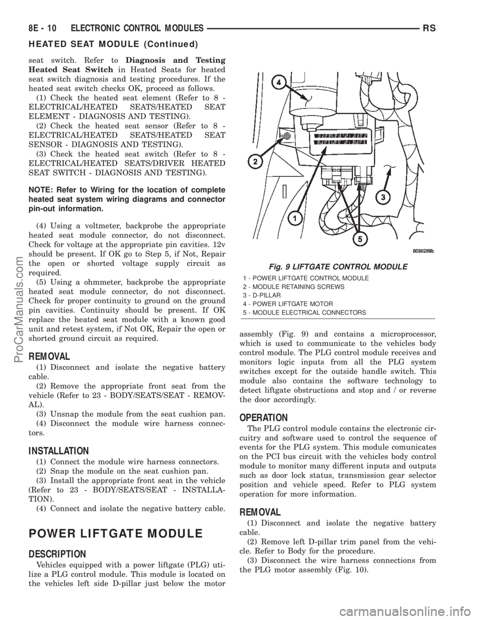
Vehicles equipped with a power liftgate (PLG) uti-
lize a PLG control module. This module is located on
the vehicles left side D-pillar just below the motorassembly (Fig. 9) and contains a microprocessor,
which is used to communicate to the vehicles body
control module. The PLG control module receives and
monitors logic inputs from all the PLG system
switches except for the outside handle switch. This
module also contains the software technology to
detect liftgate obstructions and stop and / or reverse
the door accordingly.
OPERATION
The PLG control module contains the electronic cir-
cuitry and software used to control the sequence of
events for the PLG system. This module comunicates
on the PCI bus circuit with the vehicles body control
module to monitor many different inputs and outputs
such as door lock status, transmission gear selector
position and vehicle speed. Refer to PLG system
operation for more information.
REMOVAL
(1) Disconnect and isolate the negative battery
cable.
(2) Remove left D-pillar trim panel from the vehi-
cle. Refer to Body for the procedure.
(3) Disconnect the wire harness connections from
the PLG motor assembly (Fig. 10).
Fig. 9 LIFTGATE CONTROL MODULE
1 - POWER LIFTGATE CONTROL MODULE
2 - MODULE RETAINING SCREWS
3 - D-PILLAR
4 - POWER LIFTGATE MOTOR
5 - MODULE ELECTRICAL CONNECTORS
8E - 10 ELECTRONIC CONTROL MODULESRS
HEATED SEAT MODULE (Continued)
ProCarManuals.com
Page 370 of 2399

MEMORY SEAT/MIRROR
MODULE
DESCRIPTION
Vehicles equipped with the memory seat/mirror
option, utilize a memory module located under the
drivers front seat. This module is basically wired in-
line between the power seat switch and the power
seat track/adjuster motors, or in-line between the
power mirror switch and the power side view mir-
ror(s) motor(s). The MSMM contains a central pro-
cessing unit that communicates with other modules
on the Programmable Communications Interface
(PCI) data bus network.
The Memory Seat/Mirror Module (MSMM) receives
hard wired inputs from the driver power seat switch
and the potentiometers on each of the driver side
power seat track motors, or from the power mirror
switch and the potentiometers on the side view mir-
ror. The MSMM receives messages over the PCI data
bus from the Body Control Module (BCM) (memory
switch status), the Powertrain Control Module (PCM)
(vehicle speed status). The MSMM will prevent the
seat memory recall function from being initiated if
the driver side seat belt is buckled, if the transmis-
sion gear selector lever is not in the Park or Neutral
positions, or if the vehicle is moving.
For diagnosis of the MSMM or the PCI data bus, a
DRB IIItscan tool and the proper Diagnostic Proce-
dures manual are recommended. The MSMM cannot
be repaired and, if faulty or damaged, it must be
replaced. Refer toMemory Systemin the Power
Seat or Power Mirror section of this manual for more
information on the memory system option.
OPERATION
When memory system operation is requested
(depressing of the memory switch), a resistor multi-
plexed signal is sent from the memory switch to the
body control module (BCM). The body control module
will then send the appropriate signals out to the
memory/mirror seat module, the memory/mirror seat
module then applies the voltage supply to the power
seat track or side-view mirror if the proper require-
ments are met. The vehicle speed must equal zero
and the transmission must be in park or neutral in
order for the memory system to function.
DIAGNOSIS AND TESTING - MEMORY
SEAT/MIRROR MODULE
Visually inspect the related wiring harness connec-
tors. Look for broken, bent, pushed out, or corroded
terminals. If any of the above conditions are present,
repair as necessary. If not, use a DRB IIItscan tool
and the proper Diagnostic Procedures Manual to testthe memory/mirror seat module. For complete circuit
diagrams, refer toWiring Diagrams.
REMOVAL
(1) Disconnect and isolate the battery negative
cable.
(2) Remove the driver side front bucket seat
retaining nuts from under the vehicle (Refer to 23 -
BODY/SEATS/SEAT - REMOVAL).
(3) Lift the drivers seat up and out of the mount-
ing holes in the floor pan and lay the seat rearward
to access the module located under the seat. It is not
necessary to disconnect the seat electrical, just use
care not to damage the wiring by over-extending.
(4) Disconnect the memory/mirror seat module
electrical connectors. Depress the retaining tab and
pull straight apart.
(5) Remove the module retaining bolts and remove
the module from the bracket.
INSTALLATION
(1) Position and install the module retaining bolts.
(2) Connect the memory/mirror seat module elec-
trical connectors.
(3) Position the drivers seat in the mounting holes
in the floor pan.
(4) Install the driver side front bucket seat retain-
ing nuts from under the vehicle (Refer to 23 - BODY/
SEATS/SEAT - INSTALLATION).
(5) Connect the battery negative cable.
SLIDING DOOR CONTROL
MODULE
DESCRIPTION
Vehicles equipped with a power sliding door utilize
a sliding door control module. The sliding door con-
trol module is located behind the sliding door trim
panel in the center of the door, just above the sliding
door motor (Fig. 20). This module controls the opera-
tion of the door through the Programmable Commu-
nication Interface (PCI) J1850 data bus circuit and
the Body Control Module. The sliding door control
module contains software technology which enables it
to detect resistance to door travel and to reverse door
travel in order to avoid damage to the door or to
avoid possible personal injury if the obstruction is a
person. This feature functions in both the opening
and closing cycles. If the power sliding door system
develops any problems the control module will store
and recall Diagnostic Trouble Codes (DTC). The use
of a diagnostic scan tool, such as the DRB IIItis
required to read and troubleshoot these trouble
codes. The sliding door control module can be
RSELECTRONIC CONTROL MODULES8E-33
ProCarManuals.com
Page 373 of 2399
these sensor inputs to adjust fuel quantity and fuel
injector timing.
Limp-In Mode
If there is a fault detected with the accelerator
pedal position sensor, the ECM will set the engine
speed at 1100 RPM.
Overspeed Detection Mode
If the ECM detects engine RPM that exceeds 5200
RPM, the ECM will set a DTC in memory and illu-
minate the MIL until the DTC is cleared.
After-Run Mode
The ECM transfers RAM information to ROM and
performs an Input/Output state check.
MONITORED CIRCUITS
The ECM is able to monitor and identify most
driveability related trouble conditions. Some circuits
are directly monitored through ECM feedback cir-
cuitry. In addition, the ECM monitors the voltage
state of some circuits and compares those states with
expected values. Other systems are monitored indi-
rectly when the ECM conducts a rationality test to
identify problems. Although most subsytems of the
engine control module are either directly or indirectly
monitored, there may be occasions when diagnostic
trouble codes are not immediately identified. For a
trouble code to set, a specific set of conditions must
occur and unless these conditions occur, a DTC will
not set.
DIAGNOSTIC TROUBLE CODES
Each diagnostic trouble code (DTC) is diagnosed by
following a specific procedure. The diagnostic test
procedure contains step-by-step instruction for deter-
mining the cause of the DTC as well as no trouble
code problems. Refer to the appropriate Diesel Pow-
ertrain Diagnostic Manual for more information.
HARD CODE
A DTC that comes back within one cycle of the
ignition key is a hard code. This means that the
problem is current every time the ECM/SKIM checks
that circuit or function. Procedures in this manual
verify if the DTC is a hard code at the beginning of
each test. When the fault is not a hard code, an
intermittent test must be performed. NOTE: If the
DRBIIItdisplays faults for multiple components (i.e.
ECT, VSS, IAT sensors) identify and check the
shared circuits for possible problems before continu-
ing (i.e. sensor grounds or 5-volt supply circuits).
Refer to the appropriate schematic to identify shared
circuits. Refer to the appropriate Diesel Powertrain
Diagnostic Manual for more information.INTERMITTENT CODE
A DTC that is not current every time the ECM/
SKIM checks the circuit or function is an intermit-
tent code. Most intermittent DTCs are caused by
wiring or connector problems. Problems that come
and go like this are the most difficult to diagnose;
they must be looked for under specific conditions that
cause them.NOTE: Electromagnetic (radio)
interference can cause an intermittent system
malfunction.This interference can interrupt com-
munication between the ignition key transponder and
the SKIM. The following checks may assist you in
identifying a possible intermittent problem:
²Visually inspect the related wire harness connec-
tors. Look for broken, bent, pushed out or corroded
terminals.
²Visually inspect the related wire harness. Look
for chafed, pierced or partially broken wire.
²Refer to hotlines or technical service bulletins
that may apply. Refer to the appropriate Diesel Pow-
ertrain Diagnostic Manual for more information.
ECM DIAGNOSTIC TROUBLE CODES
IMPORTANT NOTE: Before replacing the ECM for
a failed driver, control circuit or ground circuit, be
sure to check the related component/circuit integrity
for failures not detected due to a double fault in the
circuit. Most ECM driver/control circuit failures are
caused by internal failures to components (i.e. relays
and solenoids) and shorted circuits (i.e. sensor pull-
ups, drivers and ground circuits). These faults are
difficult to detect when a double fault has occurred
and only one DTC has set. If the DRBIIItdisplays
faults for multiple components (i.e.VSS, ECT, Batt
Temp, etc.) identify and check the shared circuits for
possible problems before continuing (i.e. sensor
grounds or 5-volt supply circuits). Refer to the appro-
priate wiring diagrams to identify shared circuits.
Refer to the appropriate Diesel Powertrain Diagnos-
tic Manual for more information.
STANDARD PROCEDURE - PCM/ECM/SKIM
PROGRAMMING - DIESEL
NOTE: Before replacing the PCM/ECM for a failed
driver, control circuit or ground circuit, be sure to
check the related component/circuit integrity for
failures not detected due to a double fault in the cir-
cuit. Most PCM/ECM driver/control circuit failures
are caused by internal component failures (i.e. relay
and solenoids) and shorted circuits (i.e. pull-ups,
drivers and switched circuits). These failures are
difficult to detect when a double fault has occurred
and only one DTC has set.
8Ea - 2 ELECTRONIC CONTROL MODULESRG
ENGINE CONTROL MODULE (Continued)
ProCarManuals.com
Page 391 of 2399
(1) Turn the ignition switch to the Off position. Be
certain that all electrical accessories are turned off.
(2) Remove the nut with washer that secures the
battery hold down bracket to the battery tray and
support unit.
(3) Remove the battery hold down bracket from
the battery tray and support unit.
INSTALLATION
(1) Install the battery hold down bracket in the
battery tray and support unit.
(2) Install the nut with washer that secures the
battery hold down bracket to the battery tray and
support unit. Torque to 20 N´m (180 in. lbs.).
BATTERY CABLES
DESCRIPTION
The battery cables are large gauge, stranded cop-
per wires sheathed within a heavy plastic or syn-
thetic rubber insulating jacket. The wire used in the
battery cables combines excellent flexibility and reli-
ability with high electrical current carrying capacity.
Refer toWiring Diagramsin the index of this ser-
vice manual for the location of the proper battery
cable wire gauge information.
A clamping type female battery terminal made of
stamped metal is attached to one end of the battery
cable wire. A square headed pinch-bolt and hex nut
are installed at the open end of the female battery
terminal clamp. Large eyelet type terminals are
crimped onto the opposite end of the battery cable
wire and then solder-dipped. The battery positive
cable wires have a red insulating jacket to provide
visual identification and feature a larger female bat-
tery terminal clamp to allow connection to the larger
battery positive terminal post. The battery negative
cable wires have a black insulating jacket and a
smaller female battery terminal clamp.
The battery cables cannot be repaired and, if dam-
aged or faulty they must be replaced. Both the bat-
tery positive and negative cables are available for
service replacement only as a unit with the battery
wire harness, which may include portions of the wir-
ing circuits for the generator and other components
on some models. Refer toWiring Diagramsin the
index of this service manual for the location of more
information on the various wiring circuits included in
the battery wire harness for the vehicle being ser-
viced.
OPERATION
The battery cables connect the battery terminal
posts to the vehicle electrical system. These cables
also provide a path back to the battery for electricalcurrent generated by the charging system for restor-
ing the voltage potential of the battery. The female
battery terminal clamps on the ends of the battery
cable wires provide a strong and reliable connection
of the battery cable to the battery terminal posts.
The terminal pinch bolts allow the female terminal
clamps to be tightened around the male terminal
posts on the top of the battery. The eyelet terminals
secured to the opposite ends of the battery cable
wires from the female battery terminal clamps pro-
vide secure and reliable connection of the battery
cables to the vehicle electrical system.
The battery positive cable terminal clamp is
attached to the ends of two wires. One wire has an
eyelet terminal that connects the battery positive
cable to the B(+) terminal stud of the Integrated
Power Module (IPM), and the other wire has an eye-
let terminal that connects the battery positive cable
to the B(+) terminal stud of the engine starter motor
solenoid. The battery negative cable terminal clamp
is also attached to the ends of two wires. One wire
has an eyelet terminal that connects the battery neg-
ative cable to the vehicle powertrain through a stud
on the left side of the engine cylinder block. The
other wire has an eyelet terminal that connects the
battery negative cable to the vehicle body through a
ground screw on the left front fender inner shield,
near the battery.
DIAGNOSIS AND TESTING - BATTERY CABLE
A voltage drop test will determine if there is exces-
sive resistance in the battery cable terminal connec-
tions or the battery cable. If excessive resistance is
found in the battery cable connections, the connec-
tion point should be disassembled, cleaned of all cor-
rosion or foreign material, then reassembled.
Following reassembly, check the voltage drop for the
battery cable connection and the battery cable again
to confirm repair.
When performing the voltage drop test, it is impor-
tant to remember that the voltage drop is giving an
indication of the resistance between the two points at
which the voltmeter probes are attached.EXAM-
PLE:When testing the resistance of the battery pos-
itive cable, touch the voltmeter leads to the battery
positive cable terminal clamp and to the battery pos-
itive cable eyelet terminal at the starter solenoid
B(+) terminal stud. If you probe the battery positive
terminal post and the battery positive cable eyelet
terminal at the starter solenoid B(+) terminal stud,
you are reading the combined voltage drop in the
battery positive cable terminal clamp-to-terminal
post connection and the battery positive cable.
8F - 16 BATTERY SYSTEMRS
BATTERY HOLDDOWN (Continued)
ProCarManuals.com
Page 403 of 2399
STARTING
TABLE OF CONTENTS
page page
STARTING
DESCRIPTION.........................28
OPERATION...........................28
DIAGNOSIS AND TESTING
DIAGNOSIS AND TESTING - STARTING
SYSTEM TEST.......................28
DIAGNOSIS AND TESTING - CONTROL
CIRCUIT TEST........................31
DIAGNOSIS AND TESTING - FEED CIRCUIT
RESISTANCE TEST....................33
DIAGNOSIS AND TESTING - FEED CIRCUIT
TEST...............................33SPECIFICATIONS
STARTER ...........................34
Torques.............................34
STARTER MOTOR
REMOVAL
REMOVAL - 2.4L......................35
REMOVAL - 3.3/3.8L...................36
INSTALLATION
INSTALLATION - 2.4L..................36
INSTALLATION - 3.3/3.8L................36
STARTING
DESCRIPTION
The starting system has (Fig. 1):
²Ignition switch
²Starter relay
²Transmission Range Sensor or Park/Neutral
Switch
²Wiring harness
²Battery
²Starter motor with an integral solenoid
²Powertrain Control Module (PCM)
OPERATION
These components form two separate circuits. A
high amperage circuit that feeds the starter motor up
to 300+ amps, and a control circuit that operates on
less than 20 amps.
The PCM controls a double start over-ride safety
that does not allow the starter to be engaged if the
engine is already running.
DIAGNOSIS AND TESTING
DIAGNOSIS AND TESTING - STARTING
SYSTEM TEST
For circuit descriptions and diagrams, refer to the
Wiring Diagrams.WARNING: ON VEHICLES EQUIPPED WITH AIR-
BAGS, REFER TO THE PASSIVE RESTRAINT SYS-
TEMS BEFORE ATTEMPTING STEERING WHEEL,
STEERING COLUMN, OR INSTRUMENT PANEL
COMPONENT DIAGNOSIS OR SERVICE. FAILURE
TO TAKE THE PROPER PRECAUTIONS COULD
RESULT IN ACCIDENTAL AIRBAG DEPLOYMENT
AND POSSIBLE PERSONAL INJURY.
INSPECTION
Before removing any unit from the starting system
for repair or diagnosis, perform the following inspec-
tions:
²Battery- Visually inspect the battery for indi-
cations of physical damage and loose or corroded
cable connections. Determine the state-of-charge and
cranking capacity of the battery. Charge or replace
the battery, if required. Refer to the Battery section
for more information.
²Ignition Switch- Visually inspect the ignition
switch for indications of physical damage and loose
or corroded wire harness connections.
²Transmission Range Sensor- Visually inspect
the transmission range sensor for indications of phys-
ical damage and loose or corroded wire harness con-
nections.
²Starter Relay- Visually inspect the starter
relay for indications of physical damage and loose or
corroded wire harness connections.
8F - 28 STARTINGRS
ProCarManuals.com
Page 405 of 2399

STARTING SYSTEM DIAGNOSIS
CONDITION POSSIBLE CAUSE CORRECTION
STARTER FAILS
TO ENGAGE.1. BATTERY
DISCHARGED OR
FAULTY.1. REFER TO THE BATTERY SECTION FOR MORE
INFORMATION. CHARGE OR REPLACE BATTERY, IF
REQUIRED.
2. STARTING CIRCUIT
WIRING FAULTY.2. REFER TO FEED CIRCUIT RESISTANCE TEST AND FEED
CIRCUIT TEST IN THIS SECTION.
3. STARTER RELAY
FAULTY.3. REFER TO RELAY TEST, IN THIS SECTION. REPLACE
RELAY, IF NECESSARY.
4. IGNITION SWITCH
FAULTY.4. REFER TO IGNITION SWITCH TEST, IN THE STEERING
SECTION OR 8 WIRING DIAGRAMS. REPLACE SWITCH, IF
NECESSARY.
5. PARK/NEUTRAL
POSITION SWITCH
(AUTO TRANS) FAULTY
OR MIS-ADJUSTED.5. REFER PARK/NEUTRAL POSITION SWITCH TEST, IN THE
TRANSAXLE. SECTION FOR MORE INFORMATION. REPLACE
SWITCH, IF NECESSARY.
6. CLUTCH PEDAL
POSITION SWITCH
(MAN TRANS) FAULTY.6. REFER TO CLUTCH PEDAL POSITION SWITCH TEST, IN
THE CLUTCH. SECTION. REPLACE SWITCH, IF NECESSARY.
7. STARTER SOLENOID
FAULTY.7. REFER TO SOLENOID TEST, IN THIS SECTION. REPLACE
STARTER ASSEMBLY, IF NECESSARY.
8. STARTER ASSEMBLY
FAULTY.8. IF ALL OTHER STARTING SYSTEM COMPONENTS AND
CIRCUITS CHECK OK, REPLACE STARTER ASSEMBLY.
9. FAULTY TEETH ON
RING GEAR.9. ROTATE FLYWHEEL 360É, AND INSPECT TEETH AND RING
GEAR REPLACED IF DAMAGED.
10. PCM DOUBLE
START OVERRIDE
OUTPUT FAILURE.10. REFER TO PCM DIAGNOSTIC. CHECK FOR CONTINUITY
BETWEEN PCM AND TERMINAL 85. REPAIR OPEN CIRCUIT
AS REQUIRED. IF OK, PCM MAY BE DEFECTIVE.
STARTER
ENGAGES,
FAILS TO TURN
ENGINE.1. BATTERY
DISCHARGED OR
FAULTY.1. REFER TO THE BATTERY SECTION FOR MORE
INFORMATION. CHARGE OR REPLACE BATTERY AS
NECESSARY.
2. STARTING CIRCUIT
WIRING FAULTY.2. REFER TO THE FEED CIRCUIT RESISTANCE TEST AND
THE FEED CIRCUIT TEST IN THIS SECTION. REPAIR AS
NECESSARY.
3. STARTER ASSEMBLY
FAULTY.3. IF ALL OTHER STARTING SYSTEM COMPONENTS AND
CIRCUITS CHECK OK, REPLACE STARTER ASSEMBLY.
4. ENGINE SEIZED. 4. REFER TO THE ENGINE SECTION, FOR DIAGNOSTIC AND
SERVICE PROCEDURES.
5. LOOSE
CONNECTION AT
BATTERY, PDC,
STARTER, OR ENGINE
GROUND.5. INSPECT FOR LOOSE CONNECTIONS.
6. FAULTY TEETH ON
RING GEAR.6. ROTATE FLYWHEEL 360É, AND INSPECT TEETH AND RING
GEAR REPLACED IF DAMAGED.
8F - 30 STARTINGRS
STARTING (Continued)
ProCarManuals.com
Page 408 of 2399

tion. If that checks OK check for continuity between
PCM and the terminal 85. Repair open circuit as
required. If OK, the PCM may be defective.
SAFETY SWITCHES
For diagnostics of the Transmission Range Sensor,
refer to the Transaxle section for more information.
If equipped with Clutch Interlock/Upstop Switch,
refer to Diagnosis and Testing in the Clutch section.
IGNITION SWITCH
After testing starter solenoid and relay, test igni-
tion switch and wiring. Refer to the Ignition Section
or Wiring Diagrams for more information. Check all
wiring for opens or shorts, and all connectors for
being loose or corroded.
BATTERY
For battery diagnosis and testing, refer to the Bat-
tery section for procedures.
ALL RELATED WIRING AND CONNECTORS
Refer to Wiring Diagrams for more information.
DIAGNOSIS AND TESTING - FEED CIRCUIT
RESISTANCE TEST
Before proceeding with this operation, review Diag-
nostic Preparation and Starter Feed Circuit Tests.
The following operation will require a voltmeter,
accurate to 1/10 of a volt.
CAUTION: Ignition and Fuel systems must be dis-
abled to prevent engine start while performing the
following tests.
(1) To disable the Ignition and Fuel systems, dis-
connect the Automatic Shutdown Relay (ASD). The
ASD relay is located in the Power Distribution Cen-
ter (PDC). Refer to the PDC cover for proper relay
location.
(2) Gain access to battery terminals.
(3) With all wiring harnesses and components
properly connected, perform the following:
(a) Connect the negative lead of the voltmeter to
the battery negative post, and positive lead to the
battery negative cable clamp. Rotate and hold the
ignition switch in the START position. Observe the
voltmeter. If voltage is detected, correct poor con-
tact between cable clamp and post.
(b) Connect positive lead of the voltmeter to the
battery positive post, and negative lead to the bat-
tery positive cable clamp. Rotate and hold the igni-
tion switch key in the START position. Observe the
voltmeter. If voltage is detected, correct poor con-
tact between the cable clamp and post.(c) Connect negative lead of voltmeter to battery
negative terminal, and positive lead to engine
block near the battery cable attaching point.
Rotate and hold the ignition switch in the START
position. If voltage reads above 0.2 volt, correct
poor contact at ground cable attaching point. If
voltage reading is still above 0.2 volt after correct-
ing poor contacts, replace ground cable.
(4) Connect positive voltmeter lead to the starter
motor housing and the negative lead to the battery
negative terminal. Hold the ignition switch key in
the START position. If voltage reads above 0.2 volt,
correct poor starter to engine ground.
(a) Connect the positive voltmeter lead to the
battery positive terminal, and negative lead to bat-
tery cable terminal on starter solenoid. Rotate and
hold the ignition switch in the START position. If
voltage reads above 0.2 volt, correct poor contact at
battery cable to solenoid connection. If reading is
still above 0.2 volt after correcting poor contacts,
replace battery positive cable.
(b) If resistance tests do not detect feed circuit
failures, replace the starter motor.
DIAGNOSIS AND TESTING - FEED CIRCUIT
TEST
NOTE: The following results are based upon the
vehicle being at room temperature.
The following procedure will require a suitable
volt-ampere tester (Fig. 3).
CAUTION: Before performing any starter tests, the
ignition and fuel systems must be disabled.
(1) Check battery before performing this test. Bat-
tery must be fully charged.
(2) Connect a volt-ampere tester to the battery ter-
minals. Refer to the operating instructions provided
with the tester being used.
Fig. 3 Volt Ampere Tester
RSSTARTING8F-33
STARTING (Continued)
ProCarManuals.com