service CHRYSLER VOYAGER 2002 Service Manual
[x] Cancel search | Manufacturer: CHRYSLER, Model Year: 2002, Model line: VOYAGER, Model: CHRYSLER VOYAGER 2002Pages: 2399, PDF Size: 57.96 MB
Page 1596 of 2399
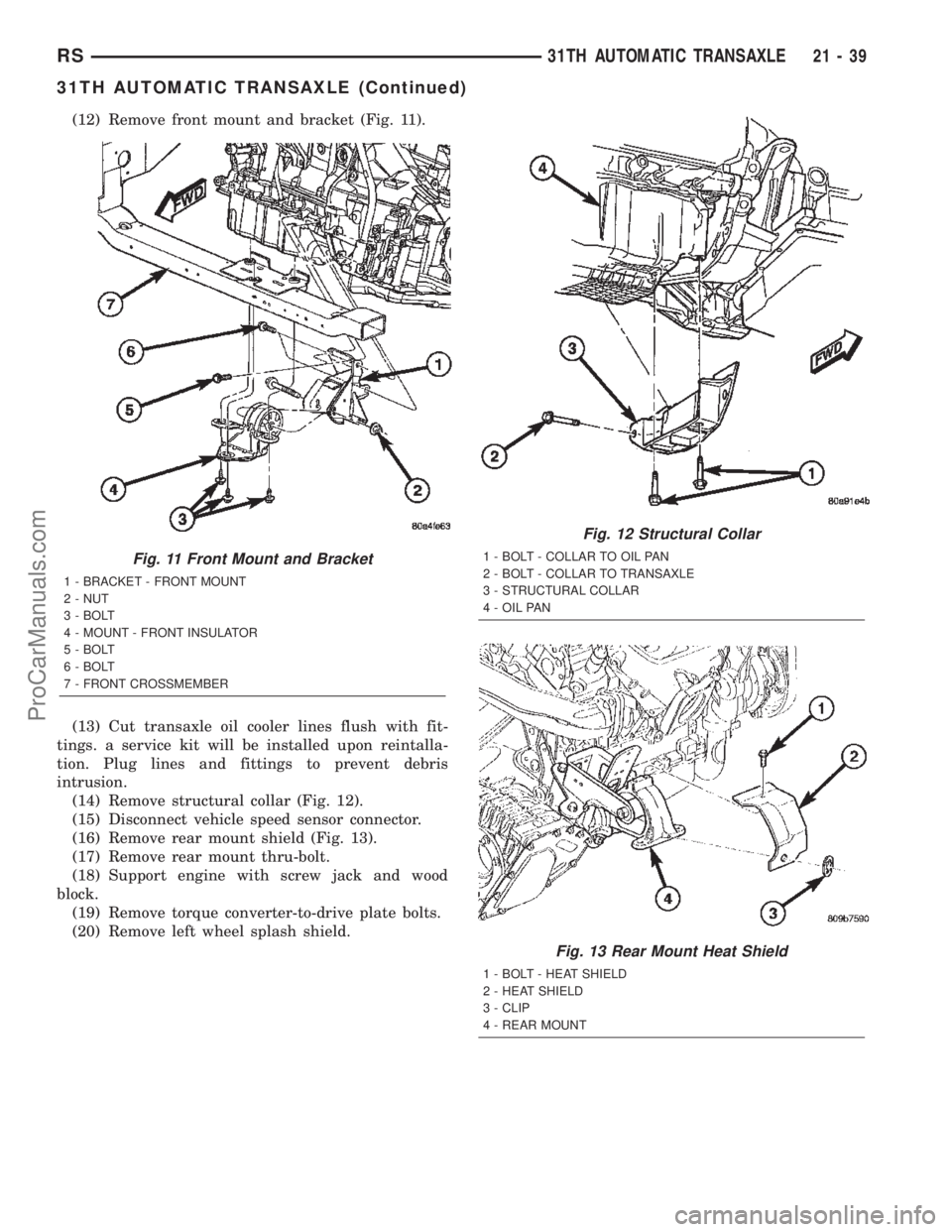
(12) Remove front mount and bracket (Fig. 11).
(13) Cut transaxle oil cooler lines flush with fit-
tings. a service kit will be installed upon reintalla-
tion. Plug lines and fittings to prevent debris
intrusion.
(14) Remove structural collar (Fig. 12).
(15) Disconnect vehicle speed sensor connector.
(16) Remove rear mount shield (Fig. 13).
(17) Remove rear mount thru-bolt.
(18) Support engine with screw jack and wood
block.
(19) Remove torque converter-to-drive plate bolts.
(20) Remove left wheel splash shield.
Fig. 11 Front Mount and Bracket
1 - BRACKET - FRONT MOUNT
2 - NUT
3 - BOLT
4 - MOUNT - FRONT INSULATOR
5 - BOLT
6 - BOLT
7 - FRONT CROSSMEMBER
Fig. 12 Structural Collar
1 - BOLT - COLLAR TO OIL PAN
2 - BOLT - COLLAR TO TRANSAXLE
3 - STRUCTURAL COLLAR
4 - OIL PAN
Fig. 13 Rear Mount Heat Shield
1 - BOLT - HEAT SHIELD
2 - HEAT SHIELD
3 - CLIP
4 - REAR MOUNT
RS31TH AUTOMATIC TRANSAXLE21-39
31TH AUTOMATIC TRANSAXLE (Continued)
ProCarManuals.com
Page 1619 of 2399
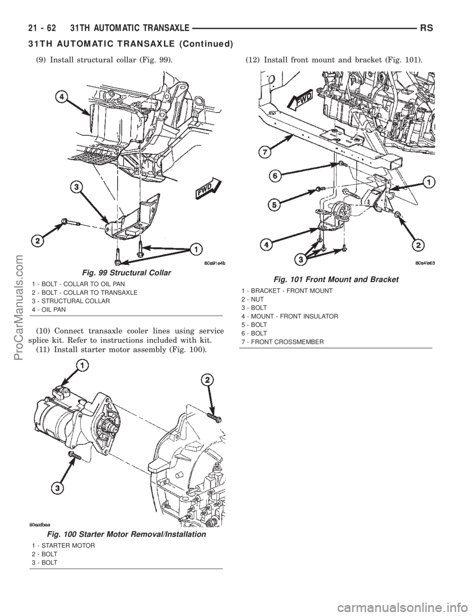
(9) Install structural collar (Fig. 99).
(10) Connect transaxle cooler lines using service
splice kit. Refer to instructions included with kit.
(11) Install starter motor assembly (Fig. 100).(12) Install front mount and bracket (Fig. 101).
Fig. 99 Structural Collar
1 - BOLT - COLLAR TO OIL PAN
2 - BOLT - COLLAR TO TRANSAXLE
3 - STRUCTURAL COLLAR
4 - OIL PAN
Fig. 100 Starter Motor Removal/Installation
1 - STARTER MOTOR
2 - BOLT
3 - BOLT
Fig. 101 Front Mount and Bracket
1 - BRACKET - FRONT MOUNT
2 - NUT
3 - BOLT
4 - MOUNT - FRONT INSULATOR
5 - BOLT
6 - BOLT
7 - FRONT CROSSMEMBER
21 - 62 31TH AUTOMATIC TRANSAXLERS
31TH AUTOMATIC TRANSAXLE (Continued)
ProCarManuals.com
Page 1648 of 2399
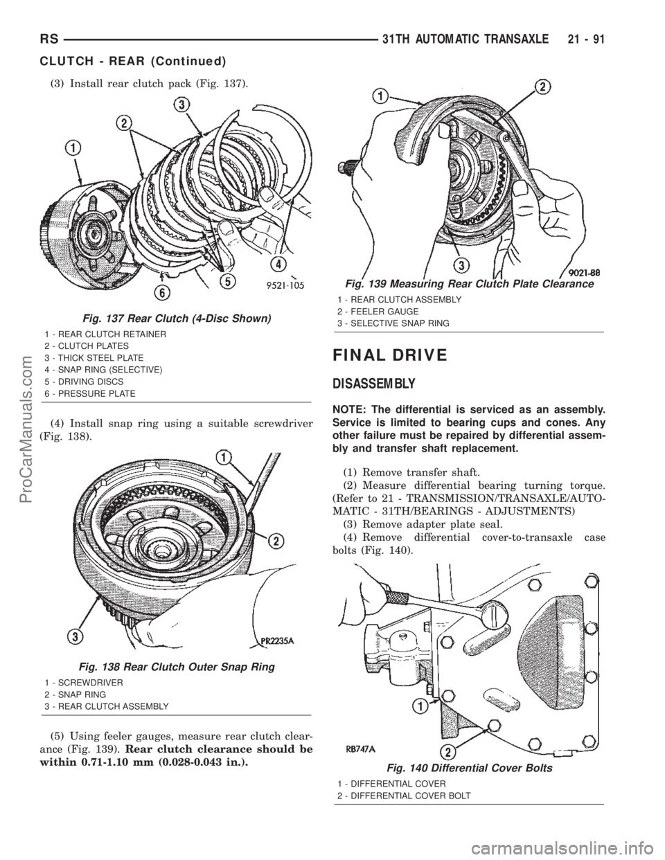
(3) Install rear clutch pack (Fig. 137).
(4) Install snap ring using a suitable screwdriver
(Fig. 138).
(5) Using feeler gauges, measure rear clutch clear-
ance (Fig. 139).Rear clutch clearance should be
within 0.71-1.10 mm (0.028-0.043 in.).
FINAL DRIVE
DISASSEMBLY
NOTE: The differential is serviced as an assembly.
Service is limited to bearing cups and cones. Any
other failure must be repaired by differential assem-
bly and transfer shaft replacement.
(1) Remove transfer shaft.
(2) Measure differential bearing turning torque.
(Refer to 21 - TRANSMISSION/TRANSAXLE/AUTO-
MATIC - 31TH/BEARINGS - ADJUSTMENTS)
(3) Remove adapter plate seal.
(4) Remove differential cover-to-transaxle case
bolts (Fig. 140).
Fig. 137 Rear Clutch (4-Disc Shown)
1 - REAR CLUTCH RETAINER
2 - CLUTCH PLATES
3 - THICK STEEL PLATE
4 - SNAP RING (SELECTIVE)
5 - DRIVING DISCS
6 - PRESSURE PLATE
Fig. 138 Rear Clutch Outer Snap Ring
1 - SCREWDRIVER
2 - SNAP RING
3 - REAR CLUTCH ASSEMBLY
Fig. 139 Measuring Rear Clutch Plate Clearance
1 - REAR CLUTCH ASSEMBLY
2 - FEELER GAUGE
3 - SELECTIVE SNAP RING
Fig. 140 Differential Cover Bolts
1 - DIFFERENTIAL COVER
2 - DIFFERENTIAL COVER BOLT
RS31TH AUTOMATIC TRANSAXLE21-91
CLUTCH - REAR (Continued)
ProCarManuals.com
Page 1651 of 2399

(14) Remove differential bearing cone (Fig. 149).
(15) Remove bearing retainer bearing cup using
Tool 6062A (Fig. 150) (Fig. 151). Remove shim and oil
baffle.
ASSEMBLY
NOTE: The differential is serviced as an assembly.
Service is limited to bearing cups and cones. Any
other failure must be repaired by differential assem-
bly and transfer shaft replacement.(1) Install shim and bearing cup using Tool 5052
and driver handle C-4171 (Fig. 152). Install bearing
cup into extension housing using Tool 6536 and
driver handle C-4171.
Fig. 149 Remove Differential Bearing Cone
1 - SPECIAL TOOL 5048
2 - RING GEAR
Fig. 150 Position Bearing Cup Remover Tool in
Retainer
1 - SPECIAL TOOL 6062A
2 - DIFFERENTIAL BEARING RETAINER
Fig. 151 Remove Bearing Cup using 6062A
1 - SPECIAL TOOL 6062A
2 - DIFFERENTIAL BEARING RETAINER
Fig. 152 Bearing Retainer Bearing Cup Installation
1 - SPECIAL TOOL C-4171
2 - SPECIAL TOOL 5052
3 - DIFFERENTIAL BEARING RETAINER
21 - 94 31TH AUTOMATIC TRANSAXLERS
FINAL DRIVE (Continued)
ProCarManuals.com
Page 1656 of 2399
FLUID
STANDARD PROCEDURE
STANDARD PROCEDURE - FLUID LEVEL AND
CONDITION CHECK
NOTE: The transmission and differential sump have
a common oil sump with a communicating opening
between the two.
FLUID LEVEL CHECK
The torque converter fills in both the P Park and N
Neutral positions. Place the selector lever in P Park
to be sure that the fluid level check is accurate.The
engine should be running at idle speed for at
least one minute, with the vehicle on level
ground. This will assure complete oil level sta-
bilization between differential and transmis-
sion.The fluid should be at normal operating
temperature (approximately 82 C. or 180 F.). The
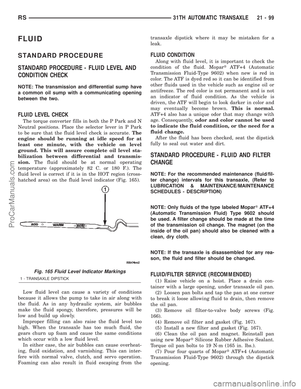
fluid level is correct if it is in the HOT region (cross-
hatched area) on the fluid level indicator (Fig. 165).
Low fluid level can cause a variety of conditions
because it allows the pump to take in air along with
the fluid. As in any hydraulic system, air bubbles
make the fluid spongy, therefore, pressures will be
low and build up slowly.
Improper filling can also raise the fluid level too
high. When the transaxle has too much fluid, the
gears churn up foam and cause the same conditions
which occur with a low fluid level.
In either case, the air bubbles can cause overheat-
ing, fluid oxidation, and varnishing. This can inter-
fere with normal valve, clutch, and servo operation.
Foaming can also result in fluid escaping from thetransaxle dipstick where it may be mistaken for a
leak.
FLUID CONDITION
Along with fluid level, it is important to check the
condition of the fluid. MopartATF+4 (Automatic
Transmission Fluid-Type 9602) when new is red in
color. The ATF is dyed red so it can be identified from
other fluids used in the vehicle such as engine oil or
antifreeze. The red color is not permanent and is not
an indicator of fluid condition. As the vehicle is
driven, the ATF will begin to look darker in color and
may eventually become brown.This is normal.
ATF+4 also has a unique odor that may change with
age. Consequently,odor and color cannot be used
to indicate the fluid condition, or the need for a
fluid change.
After the fluid has been checked, seat the dipstick
fully to seal out water and dirt.
STANDARD PROCEDURE - FLUID AND FILTER
CHANGE
NOTE: For the recommended maintenance (fluid/fil-
ter change) intervals for this transaxle, (Refer to
LUBRICATION & MAINTENANCE/MAINTENANCE
SCHEDULES - DESCRIPTION)
NOTE: Only fluids of the type labeled MoparTATF+4
(Automatic Transmission Fluid) Type 9602 should
be used. A filter change should be made at the time
of the transmission oil change. The magnet (on the
inside of the oil pan) should also be cleaned with a
clean, dry cloth.
NOTE: If the transaxle is disassembled for any rea-
son, the fluid and filter should be changed.
FLUID/FILTER SERVICE (RECOMMENDED)
(1) Raise vehicle on a hoist. Place a drain con-
tainer with a large opening, under transaxle oil pan.
(2) Loosen pan bolts and tap the pan at one corner
to break it loose allowing fluid to drain, then remove
the oil pan.
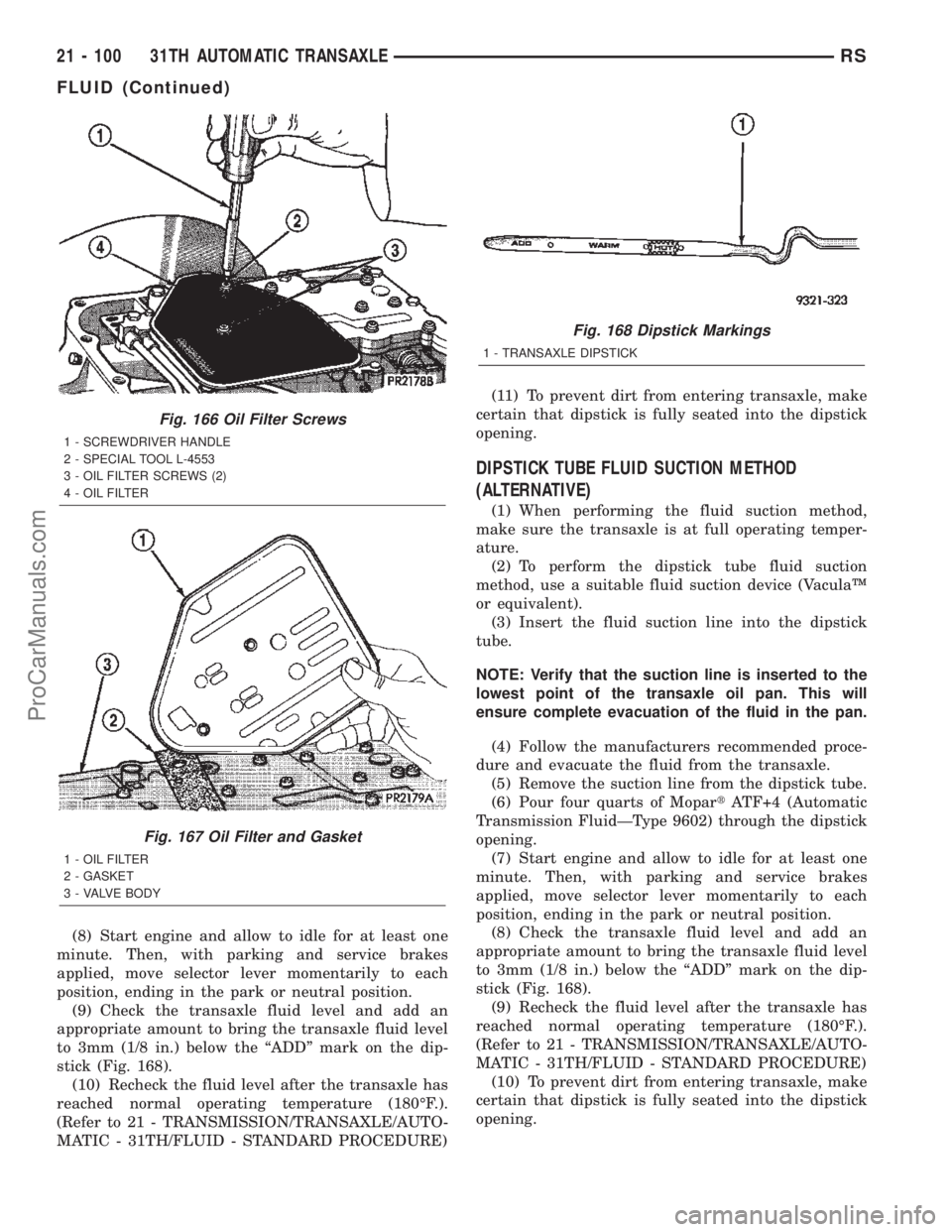
(3) Remove oil filter-to-valve body screws (Fig.
166).
(4) Remove oil filter and gasket (Fig. 167).
(5) Install a new filter and gasket (Fig. 167).
(6) Clean the oil pan and magnet. Reinstall pan
using new MopartSilicone Rubber Adhesive Sealant.
Torque oil pan bolts to 19 N´m (165 in. lbs.).
(7) Pour four quarts of MopartATF+4 (Automatic
Transmission Fluid-Type 9602) through the dipstick
opening.
Fig. 165 Fluid Level Indicator Markings
1 - TRANSAXLE DIPSTICK
RS31TH AUTOMATIC TRANSAXLE21-99
ProCarManuals.com
Page 1657 of 2399
(8) Start engine and allow to idle for at least one
minute. Then, with parking and service brakes
applied, move selector lever momentarily to each
position, ending in the park or neutral position.
(9) Check the transaxle fluid level and add an
appropriate amount to bring the transaxle fluid level
to 3mm (1/8 in.) below the ªADDº mark on the dip-
stick (Fig. 168).
(10) Recheck the fluid level after the transaxle has
reached normal operating temperature (180ÉF.).
(Refer to 21 - TRANSMISSION/TRANSAXLE/AUTO-
MATIC - 31TH/FLUID - STANDARD PROCEDURE)(11) To prevent dirt from entering transaxle, make
certain that dipstick is fully seated into the dipstick
opening.
DIPSTICK TUBE FLUID SUCTION METHOD
(ALTERNATIVE)
(1) When performing the fluid suction method,
make sure the transaxle is at full operating temper-
ature.
(2) To perform the dipstick tube fluid suction
method, use a suitable fluid suction device (VaculaŸ
or equivalent).
(3) Insert the fluid suction line into the dipstick
tube.
NOTE: Verify that the suction line is inserted to the
lowest point of the transaxle oil pan. This will
ensure complete evacuation of the fluid in the pan.
(4) Follow the manufacturers recommended proce-
dure and evacuate the fluid from the transaxle.
(5) Remove the suction line from the dipstick tube.
(6) Pour four quarts of MopartATF+4 (Automatic
Transmission FluidÐType 9602) through the dipstick
opening.
(7) Start engine and allow to idle for at least one
minute. Then, with parking and service brakes
applied, move selector lever momentarily to each
position, ending in the park or neutral position.
(8) Check the transaxle fluid level and add an
appropriate amount to bring the transaxle fluid level
to 3mm (1/8 in.) below the ªADDº mark on the dip-
stick (Fig. 168).
(9) Recheck the fluid level after the transaxle has
reached normal operating temperature (180ÉF.).
(Refer to 21 - TRANSMISSION/TRANSAXLE/AUTO-
MATIC - 31TH/FLUID - STANDARD PROCEDURE)
(10) To prevent dirt from entering transaxle, make
certain that dipstick is fully seated into the dipstick
opening.
Fig. 166 Oil Filter Screws
1 - SCREWDRIVER HANDLE
2 - SPECIAL TOOL L-4553
3 - OIL FILTER SCREWS (2)
4 - OIL FILTER
Fig. 167 Oil Filter and Gasket
1 - OIL FILTER
2 - GASKET
3 - VALVE BODY
Fig. 168 Dipstick Markings
1 - TRANSAXLE DIPSTICK
21 - 100 31TH AUTOMATIC TRANSAXLERS
FLUID (Continued)
ProCarManuals.com
Page 1663 of 2399

mittent, or it takes more than 20 seconds to collect
one quart of fluid, (Refer to 21 - TRANSMISSION/
TRANSAXLE/AUTOMATIC - 31TH - DIAGNOSIS
AND TESTING) for further diagnosis.
(4) Re-connect theTo coolerline to the transmis-
sion cooler inlet using a service splice kit. Refer to
instructions included with the kit.
(5) Refill the transmission to proper level. (Refer
to 21 - TRANSMISSION/TRANSAXLE/AUTOMATIC
- 31TH/FLUID - STANDARD PROCEDURE)
DISASSEMBLY
(1) Remove reaction shaft support-to-pump body
bolts.
(2) Remove reaction shaft support, and the inner
and outer pump gears (Fig. 183).
CLEANING
Clean pump and support components with solvent
and dry them with compressed air.
INSPECTION
(1) Check condition of the seal rings and thrust
washer on the reaction shaft support. The seal rings
do not need to be replaced unless cracked, broken, or
severely worn.
(2) Visually inspect the pump and support compo-
nents. Replace the pump assembly if the seal ring
grooves or machined surfaces are worn, scored, pit-
ted, or damaged. Replace the pump assembly if the
gears if pitted, worn chipped, or damaged.
(3) Inspect the pump bushing. Then check the
reaction shaft support bushing. Replace the pump
assembly if either bushing is heavily worn, scored or
damaged.
(4) Clearance between outer gear and reaction
shaft housing should be 0.010 to 0.063 mm (0.0004 to
0.0025 in.). Clearance between inner gear and reac-
tion shaft housing should be 0.010 to 0.063 mm
(0.0004 to 0.0025 in.). Both clearances can be mea-
sured at the same time by installing the gears in the
pump body and measure pump component clearances
as follows:
Fig. 183 Oil Pump Assembly
1 - REACTION SHAFT SUPPORT
2 - INNER GEAR
3 - PUMP BODY4 - PUMP BUSHING
5 - OUTER GEAR
21 - 106 31TH AUTOMATIC TRANSAXLERS
OIL PUMP (Continued)
ProCarManuals.com
Page 1679 of 2399

ADJUSTMENTS
THROTTLE VALVE LINKAGE ADJUSTMENT
The throttle valve linkage adjustment is very
important to proper transaxle operation. This adjust-
ment positions a valve which controls shift speed,
shift quality, and part throttle downshift sensitivity.
If the setting is too short, early shifts and slippage
between shifts may occur. If the setting is too long,
shifts may be delayed and part throttle downshifts
may be very sensitive.
LINKAGE ADJUSTMENT PROCEDURE
(1) Perform transaxle throttle valve linkage
adjustment while engine is at normal operating tem-
perature.
(2) Using small screwdriver, disengage adjustment
lock at transaxle.
(3) Rotate lever at transaxle all the way to the left
side of vehicle against stop.
(4) Slide cable adjuster until cable core end
touches clip at throttle valve lever.
(5) Press adjuster lock (Fig. 228) to retain setting.
TORQUE CONVERTER
DESCRIPTION
The torque converter (Fig. 229) is a hydraulic
device that couples the engine crankshaft to the
transmission. The torque converter consists of an
outer shell with an internal turbine, a stator, an
overrunning clutch, an impeller and an electronically
applied converter clutch. The converter clutch pro-
vides reduced engine speed and greater fuel economy
when engaged. Clutch engagement also provides
reduced transmission fluid temperatures. The con-
verter clutch engages in third gear. The torque con-
verter hub drives the transmission oil (fluid) pump.
The torque converter is a sealed, welded unit that
is not repairable and is serviced as an assembly.
CAUTION: The torque converter must be replaced if
a transmission failure resulted in large amounts of
metal or fiber contamination in the fluid. If the fluid
is contaminated, flush the fluid cooler and lines.
Fig. 228 Throttle Valve Cable Adjustment Lock
1 - ADJUSTER LOCK
Fig. 229 Torque Converter Assembly
1 - TURBINE
2 - IMPELLER
3 - HUB
4-STATOR
5 - CONVERTER CLUTCH DISC
6 - DRIVE PLATE
21 - 122 31TH AUTOMATIC TRANSAXLERS
THROTTLE VALVE CABLE (Continued)
ProCarManuals.com
Page 1685 of 2399

(8) Install the transmission in the vehicle. (Refer
to 21 - TRANSMISSION/TRANSAXLE/AUTOMATIC
- 31TH - INSTALLATION)
(9) Fill the transmission with the recommended
fluid.
TRANSFER SYSTEM - OUTPUT
SHAFT/GEAR/BEARING
REMOVAL
NOTE: Transfer Gear should be removed for repair
of output shaft, to obtain an accurate output shaft
turning torque measurement upon reassembly.
(Refer to 21 - TRANSMISSION/TRANSAXLE/AUTO-
MATIC - 31TH/TRANSFER SYSTEM - REMOVAL)
NOTE: Transaxle geartrain must be removed to gain
access to and service output shaft. (Refer to 21 -
TRANSMISSION/TRANSAXLE/AUTOMATIC - 31TH -
DISASSEMBLY)
(1) Using a suitable punch, bend retaining strap
tabs flat to facilitate bolt removal (Fig. 238).
(2) Remove retaining strap and stirrup-to-gear
bolts (Fig. 239).
Fig. 237 Checking Torque Converter Seating
1 - SCALE
2 - STRAIGHTEDGE
Fig. 238 Bend Strap Tabs Flat
1 - RETAINING TABS
2 - STRAP
Fig. 239 Remove Strap Bolts
1 - RETAINING BOLTS
2 - STIRRUP
3 - STRAP
21 - 128 31TH AUTOMATIC TRANSAXLERS
TORQUE CONVERTER (Continued)
ProCarManuals.com
Page 1718 of 2399
41TE AUTOMATIC TRANSAXLE
TABLE OF CONTENTS
page page
41TE AUTOMATIC TRANSAXLE
DESCRIPTION........................162
OPERATION..........................164
DIAGNOSIS AND TESTING
DIAGNOSIS AND TESTING - 41TE
TRANSAXLE GENERAL DIAGNOSIS......164
DIAGNOSIS AND TESTING - ROAD TEST . . 165
DIAGNOSIS AND TESTING - HYDRAULIC
PRESSURE TESTS...................165
DIAGNOSIS AND TESTING - CLUTCH AIR
PRESSURE TESTS...................168
DIAGNOSIS AND TESTING - TORQUE
CONVERTER HOUSING FLUID LEAKAGE . . 168
REMOVAL............................169
DISASSEMBLY........................171
ASSEMBLY...........................190
INSTALLATION........................213
SCHEMATICS AND DIAGRAMS
41TE TRANSAXLE HYDRAULIC
SCHEMATICS.......................216
SPECIFICATIONS - 41TE TRANSAXLE......228
SPECIAL TOOLS
41TE AUTOMATIC TRANSAXLE.........230
ACCUMULATOR
DESCRIPTION........................236
OPERATION..........................236
AUTOSTICK SWITCH
DESCRIPTION........................237
OPERATION..........................237
DRIVING CLUTCHES
DESCRIPTION........................237
OPERATION..........................238
FINAL DRIVE
DISASSEMBLY........................238
ASSEMBLY...........................243
ADJUSTMENTS
ADJUSTMENT - DIFFERENTIAL BEARING
PRELOAD..........................246
FLUID
STANDARD PROCEDURE
FLUID LEVEL AND CONDITION CHECK . . . 249
STANDARD PROCEDURE - FLUID AND
FILTER SERVICE.....................250
GEAR SHIFT CABLE
REMOVAL............................251
INSTALLATION........................253
ADJUSTMENTS
GEARSHIFT CABLE ADJUSTMENT.......254
HOLDING CLUTCHES
DESCRIPTION........................255OPERATION..........................255
INPUT CLUTCH ASSEMBLY
DISASSEMBLY........................255
ASSEMBLY...........................263
OIL PUMP
DESCRIPTION........................272
OPERATION..........................272
STANDARD PROCEDURE - OIL PUMP
VOLUME CHECK.....................272
DISASSEMBLY........................273
ASSEMBLY...........................274
PLANETARY GEARTRAIN
DESCRIPTION........................274
OPERATION..........................274
SEAL - OIL PUMP
REMOVAL............................275
INSTALLATION........................275
SHIFT INTERLOCK SOLENOID
DESCRIPTION........................275
OPERATION..........................276
DIAGNOSIS AND TESTING - BRAKE/
TRANSMISSION SHIFT INTERLOCK
SOLENOID..........................277
REMOVAL............................277
INSTALLATION........................278
SOLENOID/PRESSURE SWITCH ASSY
DESCRIPTION........................279
OPERATION..........................280
REMOVAL............................280
INSTALLATION........................281
SPEED SENSOR - INPUT
DESCRIPTION........................281
OPERATION..........................282
REMOVAL............................282
INSTALLATION........................283
SPEED SENSOR - OUTPUT
DESCRIPTION........................283
OPERATION..........................283
REMOVAL............................284
INSTALLATION........................284
TORQUE CONVERTER
DESCRIPTION........................285
OPERATION..........................289
REMOVAL............................290
INSTALLATION........................290
TRANSMISSION CONTROL RELAY
DESCRIPTION........................291
OPERATION..........................291
TRANSMISSION RANGE SENSOR
DESCRIPTION........................291
RS41TE AUTOMATIC TRANSAXLE21 - 161
ProCarManuals.com