sensor CHRYSLER VOYAGER 2002 Service Manual
[x] Cancel search | Manufacturer: CHRYSLER, Model Year: 2002, Model line: VOYAGER, Model: CHRYSLER VOYAGER 2002Pages: 2399, PDF Size: 57.96 MB
Page 1483 of 2399

stream sensor begins to match the upstream sensor
input except for a slight time delay. By comparing
the downstream heated oxygen sensor input to the
input from the upstream sensor, the PCM calculates
catalytic convertor efficiency. Also used to establish
the upstream O2 goal voltage (switching point).
REMOVAL
REMOVAL - UPSTREAM 1/1 - 2.4L
(1) Disconnect the negative battery cable.
(2) Raise and support the vehicle.
(3) Disconnect the electrical connector (Fig. 21).
(4) Use a socket such as the Snap-OntYA8875 or
equivalent to remove the sensor
(5) When the sensor is removed, the threads must
be cleaned with an 18 mm X 1.5 + 6E tap. If using
the original sensor, coat the threads with Loctite
771±64 anti-seize compound or equivalent.
REMOVAL - UPSTREAM 1/1 - 3.3/3.8L
(1) Remove battery, refer to the Battery section for
more information.
(2) Remove the battery tray, refer to the Battery
section for more information.
(3) Disconnect the speed control vacuum harness
from servo.
(4) Disconnect the electrical connector from servo.
(5) Remove the speed control servo and bracket
and reposition.
(6) Use a socket such as the Snap-OntYA8875 or
equivalent to remove the sensor (Fig. 23).(7) When the sensor is removed, the threads must
be cleaned with an 18 mm X 1.5 + 6E tap. If using
the original sensor, coat the threads with Loctite
771±64 anti-seize compound or equivalent.
REMOVAL - DOWNSTREAM 1/2 - 2.4/3.3/3.8L
(1) Disconnect the negative battery cable.
(2) Raise and support the vehicle.
(3) Disconnect the electrical connector (Fig. 24).
(4) Use a socket such as the Snap-OntYA8875 or
equivalent to remove the sensor (Fig. 25).
(5) When the sensor is removed, the threads must
be cleaned with an 18 mm X 1.5 + 6E tap. If using
the original sensor, coat the threads with Loctite
771±64 anti-seize compound or equivalent.
INSTALLATION
INSTALLATION - UPSTREAM 1/1 - 2.4L
The engines uses two heated oxygen sensors.
(1) After removing the sensor, the exhaust mani-
fold threads must be cleaned with an 18 mm X 1.5 +
6E tap. If reusing the original sensor, coat the sensor
threads with an anti-seize compound such as Loctite
771- 64 or equivalent. New sensors have compound
on the threads and do not require an additional coat-
ing.
(2) Install sensor and tighten to 27 N´m (20 ft.
lbs.) (Fig. 21).
(3) Connect the electrical connector for the O2 sen-
sor and install onto bracket.
(4) Lower vehicle.
(5) Connect the negative battery cable.
Fig. 23 O2 SENSOR 1/1
Fig. 24 Downstream Oxygen Sensor (1/2)
1 - OXYGEN SENSOR CONNECTOR
2 - CATALYTIC CONVERTER
3 - DOWNSTREAM OXYGEN SENSOR
4 - ENGINE HARNESS CONNECTOR
14 - 32 FUEL INJECTIONRS
O2 SENSOR (Continued)
ProCarManuals.com
Page 1484 of 2399

INSTALLATION - UPSTREAM 1/1 - 3.3/3.8L
The engines uses two heated oxygen sensors.
(1) After removing the sensor, the exhaust mani-
fold threads must be cleaned with an 18 mm X 1.5 +
6E tap. If reusing the original sensor, coat the sensor
threads with an anti-seize compound such as Loctite
771- 64 or equivalent. New sensors have compound
on the threads and do not require an additional coat-
ing.
(2) Install sensor and tighten to 27 N´m (20 ft.
lbs.).
(3) Connect the electrical connector for the O2 sen-
sor and install onto bracket.
(4) Connect the electrical connector for the speed
control servo.
(5) Install the speed control servo and bracket
refer to the Speed Control Servo for more informa-
tion.
(6) Connect the speed control vacuum harness to
servo.
(7) Install the battery tray, refer to the Battery
section for more information.
(8) Install battery, refer to the Battery section for
more information.
INSTALLATION DOWNSTREAM 2/1 -
2.4/3.3/3.8L
The O2S is located on the side of the catalytic con-
verter.
Threads of new oxygen sensors are factory coated
with anti-seize compound to aid in removal.DONOT add any additional anti-seize compound to
the threads of a new oxygen sensor.
(1) Install sensor and tighten to 27 N´m (20 ft.
lbs.).
(2) Connect the electrical connector.
(3) Lower vehicle.
(4) Install the negative battery cable.
THROTTLE BODY
DESCRIPTION
The throttle body is located on the intake manifold
(Fig. 26) or (Fig. 27). Fuel does not enter the intake
manifold through the throttle body. Fuel is sprayed
into the manifold by the fuel injectors.
OPERATION
Filtered air from the air cleaner enters the intake
manifold through the throttle body. The throttle body
contains an air control passage controlled by an Idle
Air Control (IAC) motor. The air control passage is
used to supply air for idle conditions. A throttle valve
(plate) is used to supply air for above idle conditions.
Certain sensors are attached to the throttle body.
The accelerator pedal cable, speed control cable and
transmission control cable (when equipped) are con-
nected to the throttle body linkage arm.
A (factory adjusted) set screw is used to mechani-
cally limit the position of the throttle body throttle
plate.Never attempt to adjust the engine idle
speed using this screw.All idle speed functions are
controlled by the PCM.
Fig. 25 DOWNSTREAM 2/1 O2 SENSOR
Fig. 26 IAC MOTOR 2.4L
1 - Idle Air Control Motor
2 - Throttle Position Sensor
RSFUEL INJECTION14-33
O2 SENSOR (Continued)
ProCarManuals.com
Page 1485 of 2399
REMOVAL
(1) Disconnect negative cable from battery cable.
(2) Remove air inlet to throttle body hose clamp.
(3) Remove throttle and the speed control (if
equipped) cables from lever and bracket.
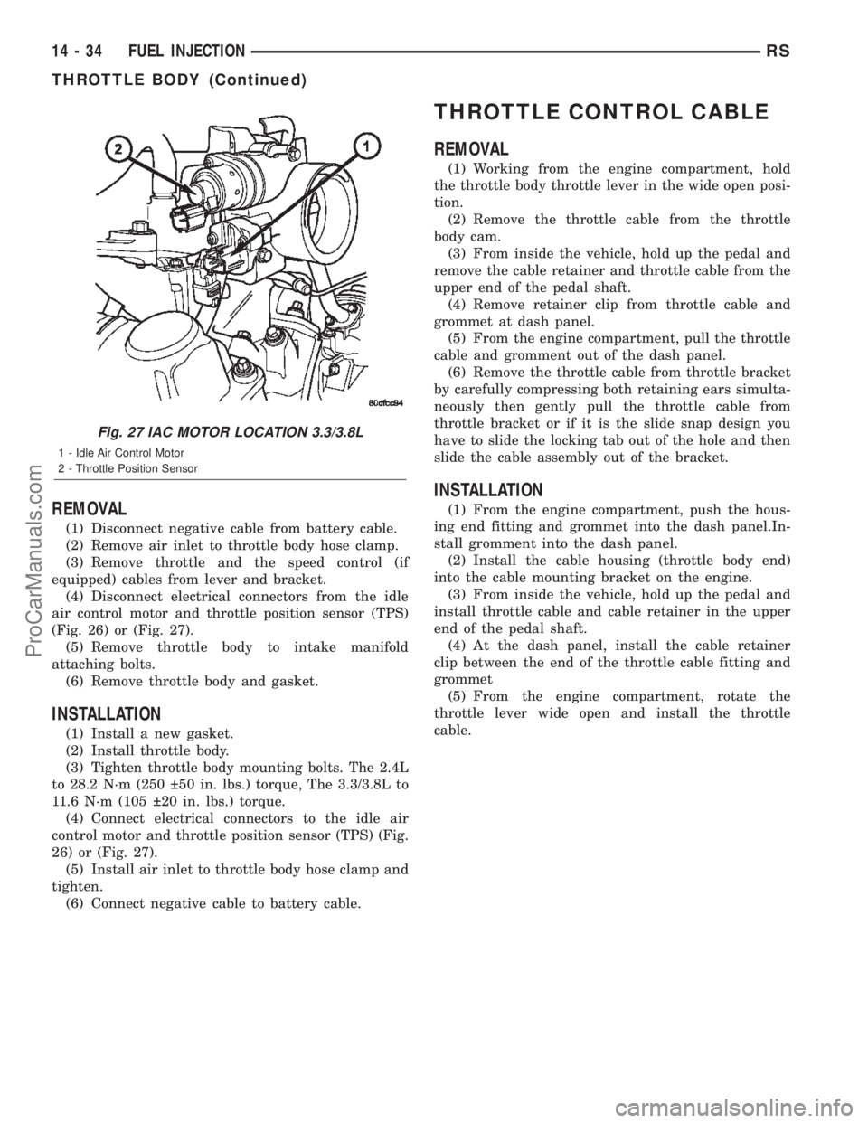
(4) Disconnect electrical connectors from the idle
air control motor and throttle position sensor (TPS)
(Fig. 26) or (Fig. 27).
(5) Remove throttle body to intake manifold
attaching bolts.
(6) Remove throttle body and gasket.
INSTALLATION
(1) Install a new gasket.
(2) Install throttle body.
(3) Tighten throttle body mounting bolts. The 2.4L
to 28.2 N´m (250 50 in. lbs.) torque, The 3.3/3.8L to
11.6 N´m (105 20 in. lbs.) torque.
(4) Connect electrical connectors to the idle air
control motor and throttle position sensor (TPS) (Fig.
26) or (Fig. 27).
(5) Install air inlet to throttle body hose clamp and
tighten.
(6) Connect negative cable to battery cable.
THROTTLE CONTROL CABLE
REMOVAL
(1) Working from the engine compartment, hold
the throttle body throttle lever in the wide open posi-
tion.
(2) Remove the throttle cable from the throttle
body cam.
(3) From inside the vehicle, hold up the pedal and
remove the cable retainer and throttle cable from the
upper end of the pedal shaft.
(4) Remove retainer clip from throttle cable and
grommet at dash panel.
(5) From the engine compartment, pull the throttle
cable and gromment out of the dash panel.
(6) Remove the throttle cable from throttle bracket
by carefully compressing both retaining ears simulta-
neously then gently pull the throttle cable from
throttle bracket or if it is the slide snap design you
have to slide the locking tab out of the hole and then
slide the cable assembly out of the bracket.
INSTALLATION
(1) From the engine compartment, push the hous-
ing end fitting and grommet into the dash panel.In-
stall gromment into the dash panel.
(2) Install the cable housing (throttle body end)
into the cable mounting bracket on the engine.
(3) From inside the vehicle, hold up the pedal and
install throttle cable and cable retainer in the upper
end of the pedal shaft.
(4) At the dash panel, install the cable retainer
clip between the end of the throttle cable fitting and
grommet
(5) From the engine compartment, rotate the
throttle lever wide open and install the throttle
cable.
Fig. 27 IAC MOTOR LOCATION 3.3/3.8L
1 - Idle Air Control Motor
2 - Throttle Position Sensor
14 - 34 FUEL INJECTIONRS
THROTTLE BODY (Continued)
ProCarManuals.com
Page 1486 of 2399
THROTTLE POSITION SENSOR
DESCRIPTION
The throttle position sensor mounts to the side of
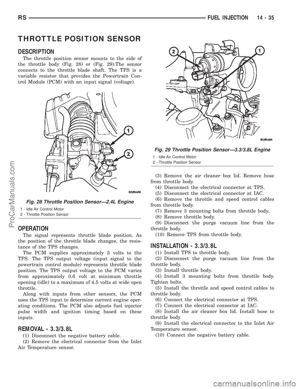
the throttle body (Fig. 28) or (Fig. 29).The sensor
connects to the throttle blade shaft. The TPS is a
variable resistor that provides the Powertrain Con-
trol Module (PCM) with an input signal (voltage).
OPERATION
The signal represents throttle blade position. As
the position of the throttle blade changes, the resis-
tance of the TPS changes.
The PCM supplies approximately 5 volts to the
TPS. The TPS output voltage (input signal to the
powertrain control module) represents throttle blade
position. The TPS output voltage to the PCM varies
from approximately 0.6 volt at minimum throttle
opening (idle) to a maximum of 4.5 volts at wide open
throttle.
Along with inputs from other sensors, the PCM
uses the TPS input to determine current engine oper-
ating conditions. The PCM also adjusts fuel injector
pulse width and ignition timing based on these
inputs.
REMOVAL - 3.3/3.8L
(1) Disconnect the negative battery cable.
(2) Remove the electrical connector from the Inlet
Air Temperature sensor.(3) Remove the air cleaner box lid. Remove hose
from throttle body.
(4) Disconnect the electrical connector at TPS.
(5) Disconnect the electrical connector at IAC.
(6) Remove the throttle and speed control cables
from throttle body.
(7) Remove 3 mounting bolts from throttle body.
(8) Remove throttle body.
(9) Disconnect the purge vacuum line from the
throttle body.
(10) Remove TPS from throttle body.
INSTALLATION - 3.3/3.8L
(1) Install TPS to throttle body.
(2) Disconnect the purge vacuum line from the
throttle body.
(3) Install throttle body.
(4) Install 3 mounting bolts from throttle body.
Tighten bolts.
(5) Install the throttle and speed control cables to
throttle body.
(6) Connect the electrical connector at TPS.
(7) Connect the electrical connector at IAC.
(8) Install the air cleaner box lid. Install hose to
throttle body.
(9) Install the electrical connector to the Inlet Air
Temperature sensor.
(10) Connect the negative battery cable.
Fig. 28 Throttle Position SensorÐ2.4L Engine
1 - Idle Air Control Motor
2 - Throttle Position Sensor
Fig. 29 Throttle Position SensorÐ3.3/3.8L Engine
1 - Idle Air Control Motor
2 - Throttle Position Sensor
RSFUEL INJECTION14-35
ProCarManuals.com
Page 1488 of 2399
FUEL SYSTEM
TABLE OF CONTENTS
page page
FUEL SYSTEM 2.5L TURBO DIESEL
DESCRIPTION - DIESEL FUEL DELIVERY
SYSTEM.............................1
WARNING - HIGH FUEL SYSTEM PRESSURE . . 1
DIAGNOSIS AND TESTING
DIAGNOSIS AND TESTING - AIR IN FUEL
SYSTEM.............................1
DIAGNOSIS AND TESTING - FUEL SUPPLY
RESTRICTIONS........................1
STANDARD PROCEDURE
STANDARD PROCEDURES - DRAINING
WATER FROM FUEL FILTER..............2STANDARD PROCEDURE - FUEL SYSTEM
AIR PURGE...........................2
STANDARD PROCEDURES - CLEANING
FUEL SYSTEM COMPONENTS............2
SPECIFICATIONS - TORQUE...............3
FUEL DELIVERY..........................4
FUEL INJECTION........................11
FUEL SYSTEM 2.5L TURBO
DIESEL
DESCRIPTION - DIESEL FUEL DELIVERY
SYSTEM
The fuel system on the 2.5L Common Rail Diesel
Engine uses a fuel injection pump and an Electronic
Control Module (ECM).
The fuel delivery system consists of the:
²Accelerator pedal
²Air cleaner housing/element
²Fuel filter/water separator
²Fuel heater
²Fuel heater relay
²Fuel transfer (lift) pump
²Fuel injection pump
²Fuel injectors
²Fuel tank
²Fuel tank filler/vent tube assembly
²Fuel tank filler tube cap
²Fuel tank module containing the rollover valve
and a fuel gauge sending unit (fuel level sensor).
²Fuel tubes/lines/hoses
²High-pressure fuel injector lines
²Low-pressure fuel supply lines
²Low-pressure fuel return line
²Overflow valve
²Quick-connect fittings
²Water draining
WARNING - HIGH FUEL SYSTEM PRESSURE
WARNING:: THE INJECTION PUMP SUPPLIES HIGH-
PRESSURE FUEL TO EACH INDIVIDUAL INJECTOR
THROUGH HIGH-PRESSURE LINES. FUEL UNDERTHIS AMOUNT OF PRESSURE CAN PENETRATE
SKIN AND CAUSE PERSONAL INJURY. WEAR
SAFETY GOGGLES AND ADEQUATE PROTECTIVE
CLOTHING. AVOID CONTACT WITH FUEL SPRAY
WHEN BLEEDING HIGH-PRESSURE FUEL LINES.
DIAGNOSIS AND TESTING
DIAGNOSIS AND TESTING - AIR IN FUEL
SYSTEM
Air will enter the fuel system whenever fuel supply
lines, separator filters, injection pump, high-pressure
lines or injectors are removed or disconnected. Air
trapped in the fuel system can result in hard start-
ing, a rough running engine, engine misfire, low
power, excessive smoke and fuel knock. After service
is performed, air must be bled from the system
before starting the engine.
Inspect the fuel system from the fuel tank to the
injectors for loose connections. Leaking fuel is an
indicator of loose connections or defective seals. Air
can also enter the fuel system between the fuel tank
and the transfer pump. Inspect the fuel tank and fuel
lines for damage that might allow air into the sys-
tem.
DIAGNOSIS AND TESTING - FUEL SUPPLY
RESTRICTIONS
LOW-PRESSURE LINES
Fuel supply line restrictions or a defective fuel
transfer pump can cause starting problems and pre-
vent engine from accelerating. The starting problems
include; low power and/or white fog like exhaust.
RGFUEL SYSTEM14a-1
ProCarManuals.com
Page 1490 of 2399
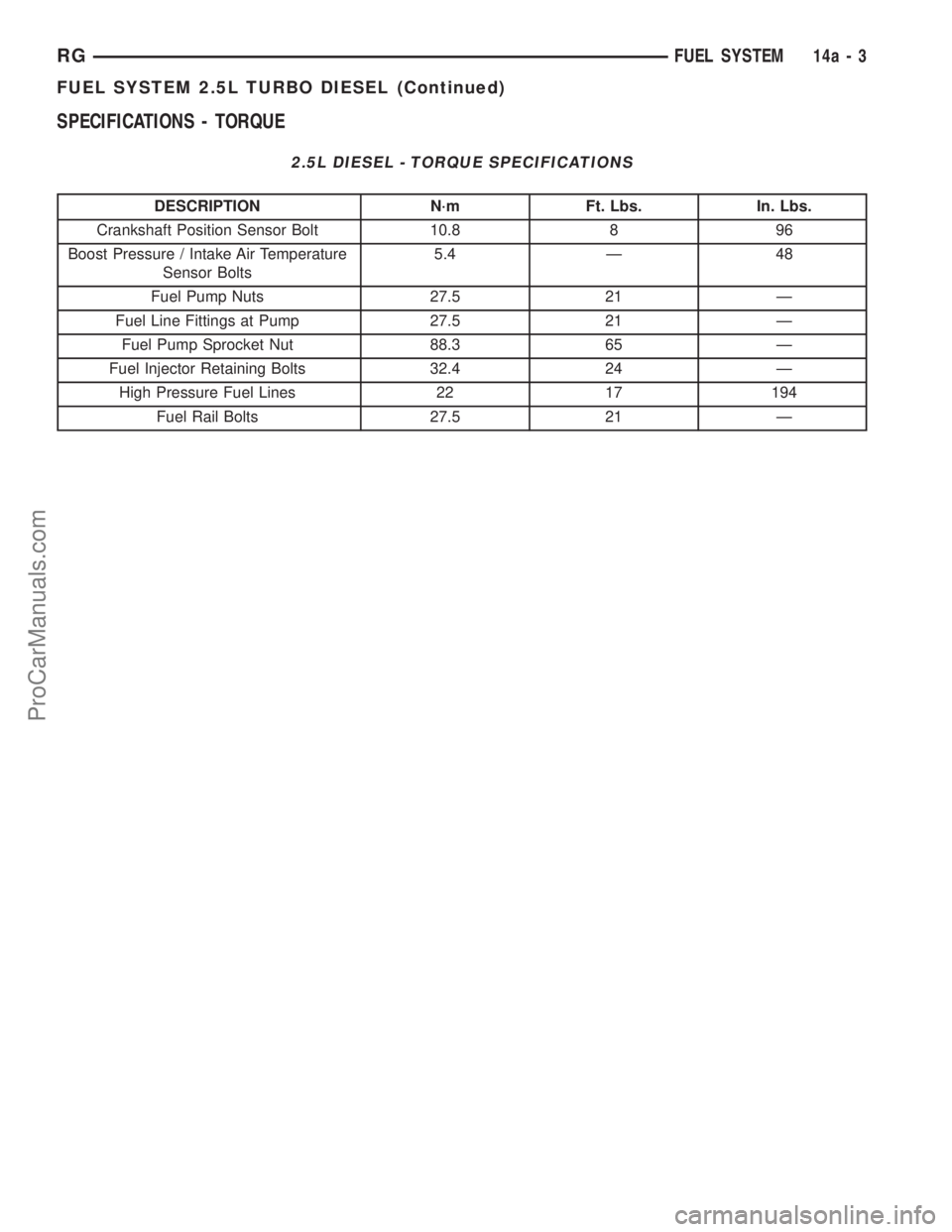
SPECIFICATIONS - TORQUE
2.5L DIESEL - TORQUE SPECIFICATIONS
DESCRIPTION N´m Ft. Lbs. In. Lbs.
Crankshaft Position Sensor Bolt 10.8 8 96
Boost Pressure / Intake Air Temperature
Sensor Bolts5.4 Ð 48
Fuel Pump Nuts 27.5 21 Ð
Fuel Line Fittings at Pump 27.5 21 Ð
Fuel Pump Sprocket Nut 88.3 65 Ð
Fuel Injector Retaining Bolts 32.4 24 Ð
High Pressure Fuel Lines 22 17 194
Fuel Rail Bolts 27.5 21 Ð
RGFUEL SYSTEM14a-3
FUEL SYSTEM 2.5L TURBO DIESEL (Continued)
ProCarManuals.com
Page 1491 of 2399

FUEL DELIVERY
TABLE OF CONTENTS
page page
FUEL RAIL
DESCRIPTION..........................4
OPERATION............................4
REMOVAL - FUEL RAIL...................4
INSTALLATION - FUEL RAIL................5
FUEL FILTER / WATER SEPARATOR
DESCRIPTION..........................5
OPERATION............................5
FUEL LINES
DESCRIPTION
DESCRIPTION........................6
DESCRIPTION - HIGH PRESSURE FUEL
LINES...............................6OPERATION - HIGH PRESSURE FUEL LINES . . 6
DIAGNOSIS AND TESTING - HIGH
PRESSURE FUEL LINES.................6
FUEL TRANSFER PUMP
DESCRIPTION..........................7
OPERATION............................7
FUEL INJECTION PUMP
DESCRIPTION..........................7
REMOVAL.............................7
INSTALLATION..........................9
WATER IN FUEL SENSOR
DESCRIPTION.........................10
OPERATION...........................10
FUEL RAIL
DESCRIPTION
The fuel rail is mounted to the cylinder head cover/
intake manifold (Fig. 1).
OPERATION
The fuel rail stores the fuel for the injectors at
high pressure. At the same time, the pressure oscil-
lations which are generated due to the high-pressure
pump delivery and the injection of fuel are dampened
by the rail volume.
The fuel rail is common to all cylinders, hence it's
name ªcommon railº. Even when large quantities of
fuel are extracted, the fuel rail maintains a constant
inner pressure. This ensures that the injection pres-
sure remains constant from the moment the injector
opens.
REMOVAL - FUEL RAIL
(1) Disconnect negative battery cable.
(2) Remove engine cover (Refer to 9 - ENGINE -
REMOVAL).
(3) Disconnect fuel injector high pressure lines.
(4) Disconnect fuel rail supply line. (Fig. 2)
(5) Disconnect fuel rail return line. (Fig. 2)
(6) Disconnect fuel rail high pressure sensor con-
nector. (Fig. 2)
(7) Remove engine electrical harness retainers
from the fuel rail retaining bolts/studs. (Fig. 2)
(8) Remove fuel rail retaining bolts and remove
fuel rail (Fig. 2).Fig. 1 ENGINE COMPONENT LOCATIONS
1 - FUEL INJECTOR RETURN LINE
2 - FUEL INJECTOR HIGH PRESSURE LINE
3 - OIL SEPARATOR
4 - FUEL INJECTOR
5 - CAMSHAFT POSITION SENSOR
6 - BOOST PRESSURE/INTAKE AIR TEMPERATURE SENSOR
7 - EGR SOLENOID
8 - FUEL PRESSURE SENSOR
9 - CYLINDER HEAD COVER/INTAKE MANIFOLD
10 - FUEL RAIL
14a - 4 FUEL DELIVERYRG
ProCarManuals.com
Page 1492 of 2399
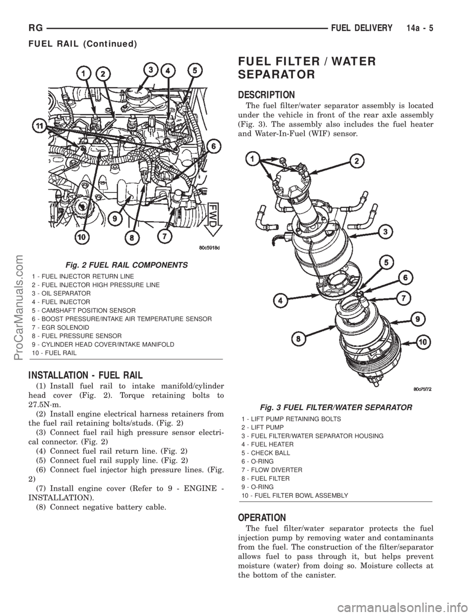
INSTALLATION - FUEL RAIL
(1) Install fuel rail to intake manifold/cylinder
head cover (Fig. 2). Torque retaining bolts to
27.5N´m.
(2) Install engine electrical harness retainers from
the fuel rail retaining bolts/studs. (Fig. 2)
(3) Connect fuel rail high pressure sensor electri-
cal connector. (Fig. 2)
(4) Connect fuel rail return line. (Fig. 2)
(5) Connect fuel rail supply line. (Fig. 2)
(6) Connect fuel injector high pressure lines. (Fig.
2)
(7) Install engine cover (Refer to 9 - ENGINE -
INSTALLATION).
(8) Connect negative battery cable.
FUEL FILTER / WATER
SEPARATOR
DESCRIPTION
The fuel filter/water separator assembly is located
under the vehicle in front of the rear axle assembly
(Fig. 3). The assembly also includes the fuel heater
and Water-In-Fuel (WIF) sensor.
OPERATION
The fuel filter/water separator protects the fuel
injection pump by removing water and contaminants
from the fuel. The construction of the filter/separator
allows fuel to pass through it, but helps prevent
moisture (water) from doing so. Moisture collects at
the bottom of the canister.
Fig. 2 FUEL RAIL COMPONENTS
1 - FUEL INJECTOR RETURN LINE
2 - FUEL INJECTOR HIGH PRESSURE LINE
3 - OIL SEPARATOR
4 - FUEL INJECTOR
5 - CAMSHAFT POSITION SENSOR
6 - BOOST PRESSURE/INTAKE AIR TEMPERATURE SENSOR
7 - EGR SOLENOID
8 - FUEL PRESSURE SENSOR
9 - CYLINDER HEAD COVER/INTAKE MANIFOLD
10 - FUEL RAIL
Fig. 3 FUEL FILTER/WATER SEPARATOR
1 - LIFT PUMP RETAINING BOLTS
2 - LIFT PUMP
3 - FUEL FILTER/WATER SEPARATOR HOUSING
4 - FUEL HEATER
5 - CHECK BALL
6 - O-RING
7 - FLOW DIVERTER
8 - FUEL FILTER
9 - O-RING
10 - FUEL FILTER BOWL ASSEMBLY
RGFUEL DELIVERY14a-5
FUEL RAIL (Continued)
ProCarManuals.com
Page 1493 of 2399

Refer to the maintenance schedules for the recom-
mended fuel filter replacement intervals.
For draining of water from canister, refer to Fuel
Filter/Water Separator Removal/Installation section.
A Water-In-Fuel (WIF) sensor is part of the fuel fil-
ter cap. Refer to Water-In-Fuel Sensor Description/
Operation.
The fuel heater is installed into the filter/separator
housing above the fuel filter. Refer to Fuel Heater
Description/Operation.
FUEL LINES
DESCRIPTION
DESCRIPTION
All fuel lines up to the fuel injection pump are con-
sidered low-pressure. This includes the fuel lines
from: the fuel tank to the fuel transfer pump, and
the fuel transfer pump to the fuel injection pump.
The fuel return lines and the fuel drain lines are also
considered low-pressure lines. High-pressure lines
are used between the fuel injection pump and the
fuel injectors. Also refer to High-Pressure Fuel Lines
Description/Operation.
DESCRIPTION - HIGH PRESSURE FUEL LINES
The high-pressure fuel lines are the 4 lines located
between the fuel injection pump and the fuel injec-
torsctor tubes. All other fuel lines are considered low-
pressure lines.
OPERATION - HIGH PRESSURE FUEL LINES
CAUTION: The high-pressure fuel lines cannot con-
tact each other or other components. Do not
attempt to weld high-pressure fuel lines or to repair
lines that are damaged. If lines are ever kinked or
bent, they must be replaced. Use only the recom-
mended lines when replacement of high-pressure
fuel line is necessary.
High-pressure fuel lines deliver fuel under
extremely high pressure from the injection pump to
the fuel injectors. The lines expand and contract from
the high-pressure fuel pulses generated during the
injection process. All high-pressure fuel lines are of
the same length and inside diameter. Correct high-
pressure fuel line usage and installation is critical to
smooth engine operation.
WARNING: USE EXTREME CAUTION WHEN
INSPECTING FOR HIGH-PRESSURE FUEL LEAKS.
INSPECT FOR HIGH-PRESSURE FUEL LEAKS WITH
A SHEET OF CARDBOARD. HIGH FUEL INJECTIONPRESSURE CAN CAUSE PERSONAL INJURY IF
CONTACT IS MADE WITH THE SKIN.
DIAGNOSIS AND TESTING - HIGH PRESSURE
FUEL LINES
High-pressure fuel line leaks can cause starting
problems and poor engine performance.
WARNING: DUE TO EXTREME FUEL PRESSURES,
USE EXTREME CAUTION WHEN INSPECTING FOR
HIGH-PRESSURE FUEL LEAKS. DO NOT GET YOUR
HAND NEAR A SUSPECTED LEAK. INSPECT FOR
HIGH-PRESSURE FUEL LEAKS WITH A SHEET OF
CARDBOARD. HIGH FUEL INJECTION PRESSURE
CAN CAUSE PERSONAL INJURY IF CONTACT IS
MADE WITH THE SKIN.
Start the engine. Move the cardboard over the
high-pressure fuel lines and check for fuel spray onto
the cardboard (Fig. 4). If a high-pressure line connec-
tion is leaking, bleed the system and tighten the con-
nection. Refer to the Air Bleed Procedure in this
group for procedures. Replace damaged, restricted or
leaking high-pressure fuel lines with the correct
replacement line.
Fig. 4 Typical Test for Leaks with Cardboard
1 - HIGH-PRESSURE LINE
2 - CARDBOARD
3 - FITTING
14a - 6 FUEL DELIVERYRG
FUEL FILTER / WATER SEPARATOR (Continued)
ProCarManuals.com
Page 1497 of 2399
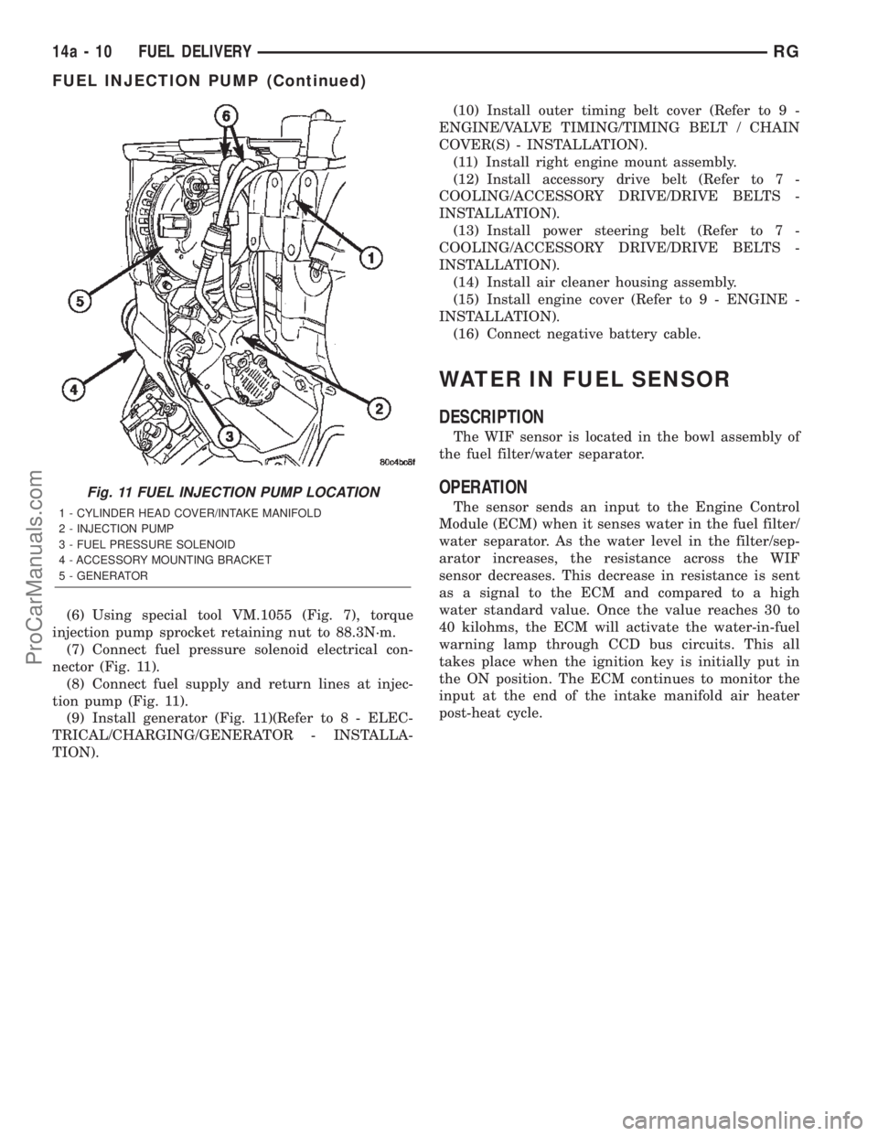
(6) Using special tool VM.1055 (Fig. 7), torque
injection pump sprocket retaining nut to 88.3N´m.
(7) Connect fuel pressure solenoid electrical con-
nector (Fig. 11).
(8) Connect fuel supply and return lines at injec-
tion pump (Fig. 11).
(9) Install generator (Fig. 11)(Refer to 8 - ELEC-
TRICAL/CHARGING/GENERATOR - INSTALLA-
TION).(10) Install outer timing belt cover (Refer to 9 -
ENGINE/VALVE TIMING/TIMING BELT / CHAIN
COVER(S) - INSTALLATION).
(11) Install right engine mount assembly.
(12) Install accessory drive belt (Refer to 7 -
COOLING/ACCESSORY DRIVE/DRIVE BELTS -
INSTALLATION).
(13) Install power steering belt (Refer to 7 -
COOLING/ACCESSORY DRIVE/DRIVE BELTS -
INSTALLATION).
(14) Install air cleaner housing assembly.
(15) Install engine cover (Refer to 9 - ENGINE -
INSTALLATION).
(16) Connect negative battery cable.
WATER IN FUEL SENSOR
DESCRIPTION
The WIF sensor is located in the bowl assembly of
the fuel filter/water separator.
OPERATION
The sensor sends an input to the Engine Control
Module (ECM) when it senses water in the fuel filter/
water separator. As the water level in the filter/sep-
arator increases, the resistance across the WIF
sensor decreases. This decrease in resistance is sent
as a signal to the ECM and compared to a high
water standard value. Once the value reaches 30 to
40 kilohms, the ECM will activate the water-in-fuel
warning lamp through CCD bus circuits. This all
takes place when the ignition key is initially put in
the ON position. The ECM continues to monitor the
input at the end of the intake manifold air heater
post-heat cycle.
Fig. 11 FUEL INJECTION PUMP LOCATION
1 - CYLINDER HEAD COVER/INTAKE MANIFOLD
2 - INJECTION PUMP
3 - FUEL PRESSURE SOLENOID
4 - ACCESSORY MOUNTING BRACKET
5 - GENERATOR
14a - 10 FUEL DELIVERYRG
FUEL INJECTION PUMP (Continued)
ProCarManuals.com