Starter CHRYSLER VOYAGER 2002 Workshop Manual
[x] Cancel search | Manufacturer: CHRYSLER, Model Year: 2002, Model line: VOYAGER, Model: CHRYSLER VOYAGER 2002Pages: 2399, PDF Size: 57.96 MB
Page 786 of 2399

8W-30 FUEL/IGNITION SYSTEM
Component Page
A/C Compressor Clutch............... 8W-30-18
A/C Compressor Clutch Relay........ 8W-30-3, 18
A/C Pressure Sensor............ 8W-30-9, 15, 25
Accelerator Pedal Position Sensor....... 8W-30-32
Adjustable Pedals Module............. 8W-30-17
Adjustable Pedals Switch............. 8W-30-17
Auto Shut Down Relay.... 8W-30-2, 5, 7, 8, 12, 13
Battery...................... 8W-30-2, 18, 26
Battery Temperature Sensor........... 8W-30-25
Body Control Module.............. 8W-30-4, 19
Boost Pressure Sensor................ 8W-30-25
Brake Lamp Switch............. 8W-30-6, 21, 31
Cabin Heater Assist................. 8W-30-22
Camshaft Position Sensor........ 8W-30-7, 13, 24
Clockspring...................... 8W-30-3, 23
Clutch Pedal Upstop Switch........... 8W-30-30
Crank Case Ventilation Heater......... 8W-30-19
Crankshaft Position Sensor....... 8W-30-7, 13, 24
Data Link Connector............... 8W-30-4, 22
Diagnostic Junction Port......... 8W-30-4, 23, 17
Dosing Pump....................... 8W-30-22
ECM/PCM Relay........ 8W-30-18, 20, 24, 26, 28
EGR Solenoid.................... 8W-30-5, 28
Engine Control Module . . . 8W-30-18, 19, 20, 21, 22,
23, 24, 25, 26, 27, 28, 29, 30, 31, 32
Engine Coolant Temp Sensor...... 8W-30-9, 15, 25
Engine Oil Pressure Sensor........... 8W-30-21
Engine Oil Pressure Switch............ 8W-30-6
Engine Oil Temperature Sensor........ 8W-30-24
Evap/Purge Solenoid.................. 8W-30-3
Front Control Module...... 8W-30-3, 4, 17, 22, 30
Fuel Heater........................ 8W-30-29
Fuel Heater Relay................ 8W-30-19, 29
Fuel Injector No. 1............. 8W-30-8, 12, 27
Fuel Injector No. 2............. 8W-30-8, 12, 27
Fuel Injector No. 3............. 8W-30-8, 12, 27
Fuel Injector No. 4............. 8W-30-8, 12, 27
Fuel Injector No. 5.................. 8W-30-12
Fuel Injector No. 6.................. 8W-30-12
Fuel Pressure Sensor................ 8W-30-31
Fuel Pressure Solenoid............... 8W-30-20
Fuel Pump Module................ 8W-30-4, 19
Fuel Pump Relay.................... 8W-30-4
Fuse 14........................... 8W-30-17
Fuse 15........................ 8W-30-22, 29
Fuse 16 . . 8W-30-2, 5, 7, 8, 12, 13, 18, 20, 24, 26, 28
Fuse 17.................... 8W-30-2, 4, 19, 29Component Page
Fuse 18........................ 8W-30-18, 17
Fuse 26........................... 8W-30-31
Fuselink.......................... 8W-30-26
G100.............................. 8W-30-2
G101........................... 8W-30-2, 18
G103................... 8W-30-5, 6, 18, 19, 22
G300..................... 8W-30-6, 17, 21, 30
G302........................ 8W-30-4, 19, 29
Generator....................... 8W-30-2, 19
Glow Plug No. 1.................... 8W-30-26
Glow Plug No. 2.................... 8W-30-26
Glow Plug No. 3.................... 8W-30-26
Glow Plug No. 4.................... 8W-30-26
Glow Plug Relay.................... 8W-30-26
Idle Air Control Motor............. 8W-30-11, 14
Ignition Coil..................... 8W-30-7, 13
Ignition Switch..................... 8W-30-16
Inlet Air Temperature Sensor....... 8W-30-10, 14
Integrated Power
Module.......... 8W-30-2, 3, 4, 5, 7, 8, 12, 13,
18, 19, 20, 22, 24, 26, 28, 29, 30, 31
Knock Sensor.................... 8W-30-9, 15
Leak Detection Pump................ 8W-30-16
Left Speed Control Switch........... 8W-30-3, 23
Lift Pump Motor.................... 8W-30-29
Lift Pump Relay.................... 8W-30-29
Manifold Absolute Pressure Sensor.... 8W-30-9, 15
Mass Air Flow Sensor................ 8W-30-20
Oxygen Sensor 1/1 Upstream........... 8W-30-5
Oxygen Sensor 1/2 Downstream......... 8W-30-5
Park/Neutral Position Switch.......... 8W-30-11
Power Mirror Switch................. 8W-30-17
Powertrain Control Module . 8W-30-2, 3, 4, 5, 6, 10,
11, 7, 8, 9, 12, 13, 14, 15, 16
Radiator Fan Relay................... 8W-30-3
Radiator Fan Relay No. 1............. 8W-30-31
Radiator Fan Relay No. 2............. 8W-30-31
Radiator Fan Relay No. 3............. 8W-30-31
Right Speed Control Switch......... 8W-30-3, 23
Speed Control Servo.................. 8W-30-6
Starter Motor Relay............... 8W-30-4, 19
Throttle Position Sensor........... 8W-30-10, 14
Torque Converter Clutch Solenoid....... 8W-30-16
Transmission Control Module . . 8W-30-7, 10, 11, 14
Transmission Range Sensor......... 8W-30-11, 14
Vehicle Speed Sensor............ 8W-30-7, 11, 28
Water In Fuel Sensor................ 8W-30-30
RS8W-30 FUEL/IGNITION SYSTEM8W-30-1
ProCarManuals.com
Page 1087 of 2399

ENGINE CONTROL MODULE C1 (DIESEL) - BLACK 81 WAY
CAV CIRCUIT FUNCTION
55 N7 20DB/OR VEHICLE SPEED SENSOR SIGNAL
56 C918 20BK/LB A/C PRESSURE SENSOR GROUND
57 - -
58 K4 20BK/LB LOW IDLE POSITION SWITCH GROUND
59 - -
60 K9 20LB FUEL PRESSURE SENSOR 5 VOLT SUPPLY
61 K51 20BR/WT ECM/PCM RELAY CONTROL
62 - -
63 D21 20WT/BR SCI TRANSMIT
64 K151 20WT LOW IDLE POSITION SWITCH SENSE
65 - -
66 K936 20BR/YL ENGINE OIL PRESSURE SENSOR GROUND
67 - -
68 - -
69 C13 20LB/OR A/C COMPRESSOR CLUTCH RELAY CONTROL
70 N210 20DB/DG LOW SPEED RADIATOR FAN RELAY CONTROL
71 - -
72 N21 20DB/TN LIFT PUMP RELAY CONTROL
73 - -
74 T752 20DG/OR ENGINE STARTER MOTOR RELAY CONTROL
75 - -
76 - -
77 K152 20DB/WT GLOW PLUG RELAY CONTROL
78 N122 20DB/YL HIGH SPEED RADIATOR FAN DUAL RELAY CONTROL
79 - -
80 K87 20BR FUEL PRESSURE SOLENOID CONTROL
81 K87 20BR FUEL PRESSURE SOLENOID CONTROL
8W - 80 - 56 8W-80 CONNECTOR PIN-OUTSRS
ProCarManuals.com
Page 1099 of 2399

INTEGRATED POWER MODULE C3 (DIESEL) - YELLOW/RED 20 WAY
CAV CIRCUIT FUNCTION
1 N21 20DB/TN LIFT PUMP RELAY CONTROL
2- -
3 T751 20YL FUSED IGNITION SWITCH OUTPUT (START)
4 T2 18DG/WT TRS REVERSE SENSE
5 N2 18DB/YL LIFT PUMP RELAY OUTPUT
6 F202 18PK/GY FUSED IGNITION SWITCH OUTPUT (RUN-START)
7 C3 18DB/YL A/C COMPRESSOR CLUTCH RELAY OUTPUT
8 Z114 18BK/LG GROUND
9 C13 20LB/OR A/C COMPRESSOR CLUTCH RELAY CONTROL
10 A119 16RD/OR FUSED B(+)
11 C41 20LB/DG CABIN HEATER ASSIST CONTROL
12 T753 20DG/YL FUSED IGNITION SWITCH OUTPUT (START)
13 - -
14 T752 20DG/OR ENGINE STARTER MOTOR RELAY CONTROL
15 Z116 18BK/VT GROUND
16 K51 20BR/WT ECM/PCM RELAY CONTROL
17 F202 18PK/GY FUSED IGNITION SWITCH OUTPUT (RUN-START)
18 - -
19 K342 16BR/WT ECM/PCM RELAY OUTPUT
20 - -
INTEGRATED POWER MODULE C3 (GAS) - NATURAL/RED 20 WAY
CAV CIRCUIT FUNCTION
1 Z115 20BK/OR (EATX) (3.3L/3.8L) GROUND
1 Z115 18BK/OR (EATX) (2.4L) GROUND
2 F1 18PK/WT (EATX) FCM OUTPUT (UNLOCK-RUN-START)
3 T751 18YL (EATX) FUSED IGNITION SWITCH OUTPUT (START)
4 T2 18DG/WT TRS REVERSE SENSE
5 T16 18YL/OR (EATX) TRANSMISSION CONTROL RELAY OUTPUT
6 T15 18YL/BR (EATX) TRANSMISSION CONTROL RELAY CONTROL
7 C3 18DB/YL A/C COMPRESSOR CLUTCH RELAY OUTPUT
8 K31 18BR FUEL PUMP RELAY CONTROL
9 C13 18LB/OR A/C COMPRESSOR CLUTCH RELAY CONTROL
10 A104 18YL/RD (EATX) FUSED B(+)
11 - -
12 - -
13 D25 18WT/VT (EATX) PCI BUS (EATX)
14 T752 18DG/OR ENGINE STARTER MOTOR RELAY CONTROL
15 Z116 18BK/VT GROUND
16 K51 18BR/WT AUTOMATIC SHUT DOWN RELAY CONTROL
17 F202 18PK/GY FUSED IGNITION SWITCH OUTPUT (RUN-START)
18 K173 18BR/VT RADIATOR FAN RELAY CONTROL
19 F202 18PK/GY FUSED IGNITION SWITCH OUTPUT (RUN-START)
20 A109 18OR/RD FUSED B(+)
8W - 80 - 68 8W-80 CONNECTOR PIN-OUTSRS
ProCarManuals.com
Page 1100 of 2399

INTEGRATED POWER MODULE C4 - BLUE 10 WAY
CAV CIRCUIT FUNCTION
1 Z127 12BK/DG (GAS) GROUND
2 T750 12YL/GY ENGINE STARTER MOTOR RELAY OUTPUT
3 K342 16BR/WT (DIESEL) ECM/PCM RELAY OUTPUT
3 K342 16BR/WT (GAS) AUTOMATIC SHUT DOWN RELAY OUTPUT
4 F500 16DG/PK (EXCEPT MTX) FUSED IGNITION SWITCH OUTPUT (RUN)
5- -
6 D25 16WT/VT (ANTILOCK BRAKES) PCI BUS
7 A107 12TN/RD (ANTILOCK BRAKES) FUSED B(+)
8 A111 12DG/RD (ANTILOCK BRAKES) FUSED B(+)
9 A710 14RD/BR (DIESEL) B(+) (HAZARD FEED)
9 A701 14BR/RD (GAS) B(+) (HAZARD FEED)
10 - -
INTEGRATED POWER MODULE C5 - BLACK 4 WAY
CAV CIRCUIT FUNCTION
1 A1 4RD B(+)
2- -
3- -
4- -
INTEGRATED POWER MODULE C6 - NATURAL 10 WAY
CAV CIRCUIT FUNCTION
1 A101 12VT/RD FUSED B(+)
2 Z117 16BK/WT GROUND
3 Z118 16BK/YL GROUND
4 A110 12OR/RD (POWER SEAT) FUSED B(+)
5- -
6- -
7 C7 12DB FUSED FRONT BLOWER MOTOR RELAY OUTPUT
8 F307 16LB/PK (ACCESSORY RELAY
POSITION)FUSED ACCESSORY RELAY OUTPUT
8 F307 16LB/PK (BATTERY POSITION) FUSED B(+)
9 A113 12WT/RD (POWER SLIDING
DOOR)FUSED B(+)
10 - -
RS8W-80 CONNECTOR PIN-OUTS8W-80-69
ProCarManuals.com
Page 1125 of 2399
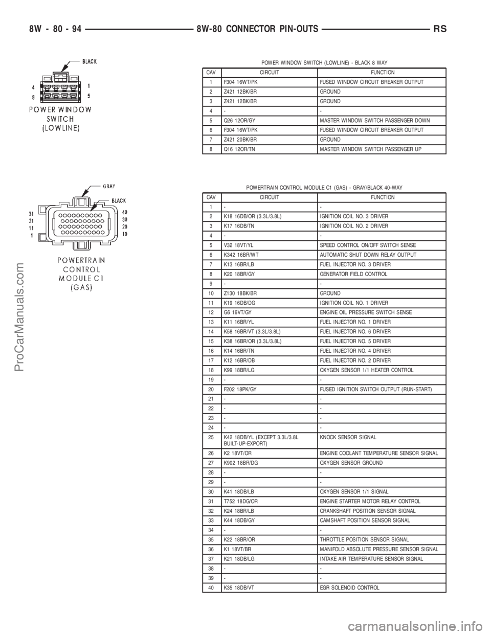
POWER WINDOW SWITCH (LOWLINE) - BLACK 8 WAY
CAV CIRCUIT FUNCTION
1 F304 16WT/PK FUSED WINDOW CIRCUIT BREAKER OUTPUT
2 Z421 12BK/BR GROUND
3 Z421 12BK/BR GROUND
4- -
5 Q26 12OR/GY MASTER WINDOW SWITCH PASSENGER DOWN
6 F304 16WT/PK FUSED WINDOW CIRCUIT BREAKER OUTPUT
7 Z421 20BK/BR GROUND
8 Q16 12OR/TN MASTER WINDOW SWITCH PASSENGER UP
POWERTRAIN CONTROL MODULE C1 (GAS) - GRAY/BLACK 40-WAY
CAV CIRCUIT FUNCTION
1- -
2 K18 16DB/OR (3.3L/3.8L) IGNITION COIL NO. 3 DRIVER
3 K17 16DB/TN IGNITION COIL NO. 2 DRIVER
4- -
5 V32 18VT/YL SPEED CONTROL ON/OFF SWITCH SENSE
6 K342 16BR/WT AUTOMATIC SHUT DOWN RELAY OUTPUT
7 K13 16BR/LB FUEL INJECTOR NO. 3 DRIVER
8 K20 18BR/GY GENERATOR FIELD CONTROL
9- -
10 Z130 18BK/BR GROUND
11 K19 16DB/DG IGNITION COIL NO. 1 DRIVER
12 G6 16VT/GY ENGINE OIL PRESSURE SWITCH SENSE
13 K11 16BR/YL FUEL INJECTOR NO. 1 DRIVER
14 K58 16BR/VT (3.3L/3.8L) FUEL INJECTOR NO. 6 DRIVER
15 K38 16BR/OR (3.3L/3.8L) FUEL INJECTOR NO. 5 DRIVER
16 K14 16BR/TN FUEL INJECTOR NO. 4 DRIVER
17 K12 16BR/DB FUEL INJECTOR NO. 2 DRIVER
18 K99 18BR/LG OXYGEN SENSOR 1/1 HEATER CONTROL
19 - -
20 F202 18PK/GY FUSED IGNITION SWITCH OUTPUT (RUN-START)
21 - -
22 - -
23 - -
24 - -
25 K42 18DB/YL (EXCEPT 3.3L/3.8L
BUILT-UP-EXPORT)KNOCK SENSOR SIGNAL
26 K2 18VT/OR ENGINE COOLANT TEMPERATURE SENSOR SIGNAL
27 K902 18BR/DG OXYGEN SENSOR GROUND
28 - -
29 - -
30 K41 18DB/LB OXYGEN SENSOR 1/1 SIGNAL
31 T752 18DG/OR ENGINE STARTER MOTOR RELAY CONTROL
32 K24 18BR/LB CRANKSHAFT POSITION SENSOR SIGNAL
33 K44 18DB/GY CAMSHAFT POSITION SENSOR SIGNAL
34 - -
35 K22 18BR/OR THROTTLE POSITION SENSOR SIGNAL
36 K1 18VT/BR MANIFOLD ABSOLUTE PRESSURE SENSOR SIGNAL
37 K21 18DB/LG INTAKE AIR TEMPERATURE SENSOR SIGNAL
38 - -
39 - -
40 K35 18DB/VT EGR SOLENOID CONTROL
8W - 80 - 94 8W-80 CONNECTOR PIN-OUTSRS
ProCarManuals.com
Page 1158 of 2399
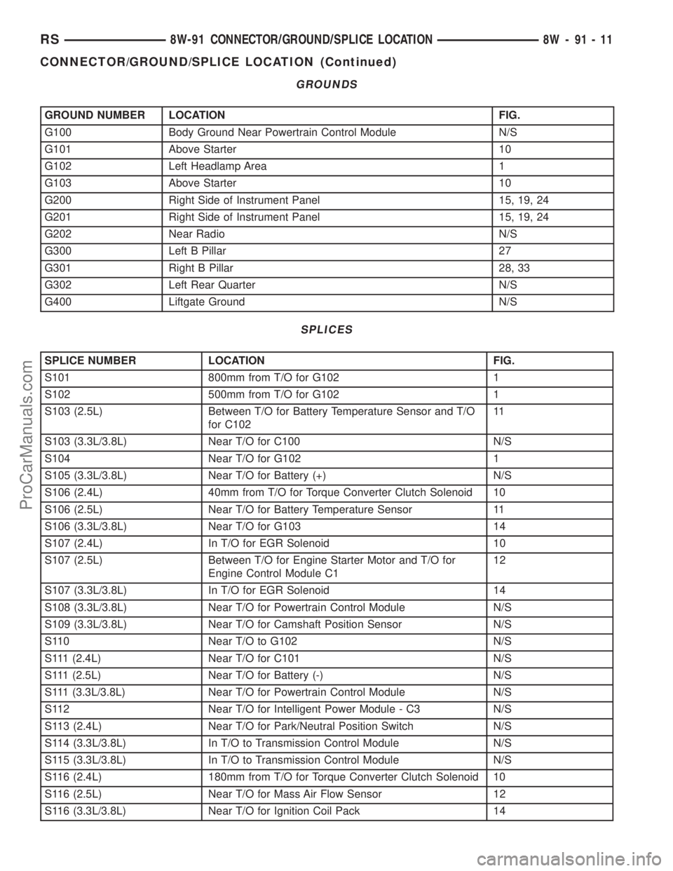
GROUNDS
GROUND NUMBER LOCATION FIG.
G100 Body Ground Near Powertrain Control Module N/S
G101 Above Starter 10
G102 Left Headlamp Area 1
G103 Above Starter 10
G200 Right Side of Instrument Panel 15, 19, 24
G201 Right Side of Instrument Panel 15, 19, 24
G202 Near Radio N/S
G300 Left B Pillar 27
G301 Right B Pillar 28, 33
G302 Left Rear Quarter N/S
G400 Liftgate Ground N/S
SPLICES
SPLICE NUMBER LOCATION FIG.
S101 800mm from T/O for G102 1
S102 500mm from T/O for G102 1
S103 (2.5L) Between T/O for Battery Temperature Sensor and T/O
for C10211
S103 (3.3L/3.8L) Near T/O for C100 N/S
S104 Near T/O for G102 1
S105 (3.3L/3.8L) Near T/O for Battery (+) N/S
S106 (2.4L) 40mm from T/O for Torque Converter Clutch Solenoid 10
S106 (2.5L) Near T/O for Battery Temperature Sensor 11
S106 (3.3L/3.8L) Near T/O for G103 14
S107 (2.4L) In T/O for EGR Solenoid 10
S107 (2.5L) Between T/O for Engine Starter Motor and T/O for
Engine Control Module C112
S107 (3.3L/3.8L) In T/O for EGR Solenoid 14
S108 (3.3L/3.8L) Near T/O for Powertrain Control Module N/S
S109 (3.3L/3.8L) Near T/O for Camshaft Position Sensor N/S
S110 Near T/O to G102 N/S
S111 (2.4L) Near T/O for C101 N/S
S111 (2.5L) Near T/O for Battery (-) N/S
S111 (3.3L/3.8L) Near T/O for Powertrain Control Module N/S
S112 Near T/O for Intelligent Power Module - C3 N/S
S113 (2.4L) Near T/O for Park/Neutral Position Switch N/S
S114 (3.3L/3.8L) In T/O to Transmission Control Module N/S
S115 (3.3L/3.8L) In T/O to Transmission Control Module N/S
S116 (2.4L) 180mm from T/O for Torque Converter Clutch Solenoid 10
S116 (2.5L) Near T/O for Mass Air Flow Sensor 12
S116 (3.3L/3.8L) Near T/O for Ignition Coil Pack 14
RS8W-91 CONNECTOR/GROUND/SPLICE LOCATION8W-91-11
CONNECTOR/GROUND/SPLICE LOCATION (Continued)
ProCarManuals.com
Page 1159 of 2399
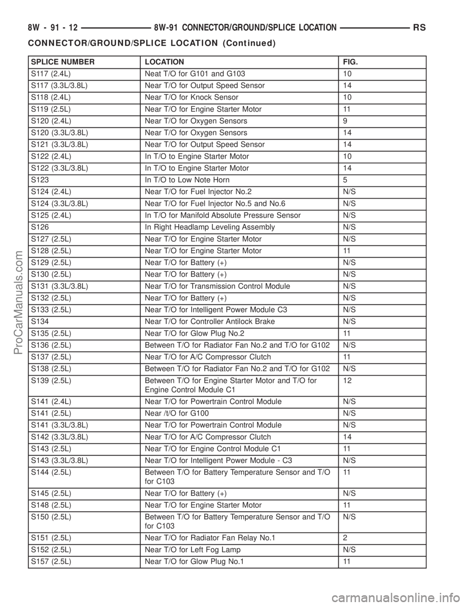
SPLICE NUMBER LOCATION FIG.
S117 (2.4L) Neat T/O for G101 and G103 10
S117 (3.3L/3.8L) Near T/O for Output Speed Sensor 14
S118 (2.4L) Near T/O for Knock Sensor 10
S119 (2.5L) Near T/O for Engine Starter Motor 11
S120 (2.4L) Near T/O for Oxygen Sensors 9
S120 (3.3L/3.8L) Near T/O for Oxygen Sensors 14
S121 (3.3L/3.8L) Near T/O for Output Speed Sensor 14
S122 (2.4L) In T/O to Engine Starter Motor 10
S122 (3.3L/3.8L) In T/O to Engine Starter Motor 14
S123 In T/O to Low Note Horn 5
S124 (2.4L) Near T/O for Fuel Injector No.2 N/S
S124 (3.3L/3.8L) Near T/O for Fuel Injector No.5 and No.6 N/S
S125 (2.4L) In T/O for Manifold Absolute Pressure Sensor N/S
S126 In Right Headlamp Leveling Assembly N/S
S127 (2.5L) Near T/O for Engine Starter Motor N/S
S128 (2.5L) Near T/O for Engine Starter Motor 11
S129 (2.5L) Near T/O for Battery (+) N/S
S130 (2.5L) Near T/O for Battery (+) N/S
S131 (3.3L/3.8L) Near T/O for Transmission Control Module N/S
S132 (2.5L) Near T/O for Battery (+) N/S
S133 (2.5L) Near T/O for Intelligent Power Module C3 N/S
S134 Near T/O for Controller Antilock Brake N/S
S135 (2.5L) Near T/O for Glow Plug No.2 11
S136 (2.5L) Between T/O for Radiator Fan No.2 and T/O for G102 N/S
S137 (2.5L) Near T/O for A/C Compressor Clutch 11
S138 (2.5L) Between T/O for Radiator Fan No.2 and T/O for G102 N/S
S139 (2.5L) Between T/O for Engine Starter Motor and T/O for
Engine Control Module C112
S141 (2.4L) Near T/O for Powertrain Control Module N/S
S141 (2.5L) Near /t/O for G100 N/S
S141 (3.3L/3.8L) Near T/O for Powertrain Control Module N/S
S142 (3.3L/3.8L) Near T/O for A/C Compressor Clutch 14
S143 (2.5L) Near T/O for Engine Control Module C1 11
S143 (3.3L/3.8L) Near T/O for Intelligent Power Module - C3 N/S
S144 (2.5L) Between T/O for Battery Temperature Sensor and T/O
for C10311
S145 (2.5L) Near T/O for Battery (+) N/S
S148 (2.5L) Near T/O for Engine Starter Motor 11
S150 (2.5L) Between T/O for Battery Temperature Sensor and T/O
for C103N/S
S151 (2.5L) Near T/O for Radiator Fan Relay No.1 2
S152 (2.5L) Near T/O for Left Fog Lamp N/S
S157 (2.5L) Near T/O for Glow Plug No.1 11
8W - 91 - 12 8W-91 CONNECTOR/GROUND/SPLICE LOCATIONRS
CONNECTOR/GROUND/SPLICE LOCATION (Continued)
ProCarManuals.com
Page 1205 of 2399
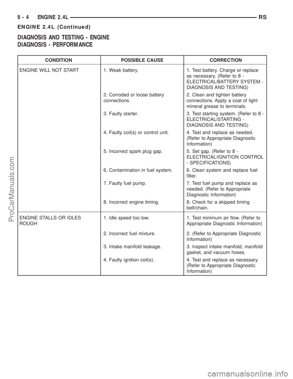
DIAGNOSIS AND TESTING - ENGINE
DIAGNOSIS - PERFORMANCE
CONDITION POSSIBLE CAUSE CORRECTION
ENGINE WILL NOT START 1. Weak battery. 1. Test battery. Charge or replace
as necessary. (Refer to 8 -
ELECTRICAL/BATTERY SYSTEM -
DIAGNOSIS AND TESTING)
2. Corroded or loose battery
connections.2. Clean and tighten battery
connections. Apply a coat of light
mineral grease to terminals.
3. Faulty starter. 3. Test starting system. (Refer to 8 -
ELECTRICAL/STARTING -
DIAGNOSIS AND TESTING)
4. Faulty coil(s) or control unit. 4. Test and replace as needed.
(Refer to Appropriate Diagnostic
Information)
5. Incorrect spark plug gap. 5. Set gap. (Refer to 8 -
ELECTRICAL/IGNITION CONTROL
- SPECIFICATIONS)
6. Contamination in fuel system. 6. Clean system and replace fuel
filter.
7. Faulty fuel pump. 7. Test fuel pump and replace as
needed. (Refer to Appropriate
Diagnostic Information)
8. Incorrect engine timing. 8. Check for a skipped timing
belt/chain.
ENGINE STALLS OR IDLES
ROUGH1. Idle speed too low. 1. Test minimum air flow. (Refer to
Appropriate Diagnostic Information)
2. Incorrect fuel mixture. 2. (Refer to Appropriate Diagnostic
Information)
3. Intake manifold leakage. 3. Inspect intake manifold, manifold
gasket, and vacuum hoses.
4. Faulty ignition coil(s). 4. Test and replace as necessary.
(Refer to Appropriate Diagnostic
Information)
9 - 4 ENGINE 2.4LRS
ENGINE 2.4L (Continued)
ProCarManuals.com
Page 1210 of 2399
(3) Remove torque converter or clutch housing
cover and inspect rear of block for evidence of oil.
Use a black light to check for the oil leak. If a leak is
present in this area, remove transmission for further
inspection.
(a) Circular spray pattern generally indicates
seal leakage or crankshaft damage.
(b) Where leakage tends to run straight down,
possible causes are a porous block, oil gallery cup
plug, bedplate to cylinder block mating surfaces
and seal bore. See proper repair procedures for
these items.
(4) If no leaks are detected, pressurize the crank-
case as previously described.
CAUTION: Do not exceed 20.6 kPa (3 psi).
(5) If the leak is not detected, very slowly turn the
crankshaft and watch for leakage. If a leak is
detected between the crankshaft and seal while
slowly turning the crankshaft, it is possible the
crankshaft seal surface is damaged. The seal area on
the crankshaft could have minor nicks or scratches
that can be polished out with emery cloth.
CAUTION: Use extreme caution when crankshaft
polishing is necessary to remove minor nicks and
scratches. The crankshaft seal flange is especially
machined to complement the function of the rear oil
seal.
(6) For bubbles that remain steady with shaft
rotation, no further inspection can be done until dis-
assembled.
(7) After the oil leak root cause and appropriate
corrective action have been identified, replace compo-
nent(s) as necessary.
DIAGNOSIS AND TESTING - CYLINDER
COMPRESSION PRESSURE TEST
The results of a cylinder compression pressure test
can be utilized to diagnose several engine malfunc-
tions.
Ensure the battery is completely charged and the
engine starter motor is in good operating condition.
Otherwise the indicated compression pressures may
not be valid for diagnosis purposes.
(1) Check engine oil level and add oil if necessary.
(2) Drive the vehicle until engine reaches normal
operating temperature. Select a route free from traf-
fic and other forms of congestion, observe all traffic
laws, and accelerate through the gears several times
briskly.
(3) Remove all spark plugs from engine. As spark
plugs are being removed, check electrodes for abnor-
mal firing indicators fouled, hot, oily, etc. Record cyl-
inder number of spark plug for future reference.(4) Remove the Auto Shutdown (ASD) relay from
the PDC.
(5) Be sure throttle blade is fully open during the
compression check.
(6) Insert compression gauge adaptor Special Tool
8116 or the equivalent, into the #1 spark plug hole in
cylinder head. Connect the 0±500 psi (Blue) pressure
transducer (Special Tool CH7059) with cable adap-
tors to the DRBIIIt. For Special Tool identification,
(Refer to 9 - ENGINE - SPECIAL TOOLS).
(7) Crank engine until maximum pressure is
reached on gauge. Record this pressure as #1 cylin-
der pressure.
(8) Repeat the previous step for all remaining cyl-
inders.
(9) Compression should not be less than 689 kPa
(100 psi) and not vary more than 25 percent from cyl-
inder to cylinder.
(10) If one or more cylinders have abnormally low
compression pressures, repeat the compression test.
(11) If the same cylinder or cylinders repeat an
abnormally low reading on the second compression
test, it could indicate the existence of a problem in
the cylinder in question.The recommended com-
pression pressures are to be used only as a
guide to diagnosing engine problems. An engine
should not be disassembled to determine the
cause of low compression unless some malfunc-
tion is present.
DIAGNOSIS AND TESTING - CYLINDER
COMBUSTION PRESSURE LEAKAGE TEST
The combustion pressure leakage test provides an
accurate means for determining engine condition.
Combustion pressure leakage testing will detect:
²Exhaust and intake valve leaks (improper seat-
ing).
²Leaks between adjacent cylinders or into water
jacket.
²Any causes for combustion/compression pressure
loss.
WARNING: DO NOT REMOVE THE PRESSURE CAP
WITH THE SYSTEM HOT AND UNDER PRESSURE
BECAUSE SERIOUS BURNS FROM COOLANT CAN
OCCUR.
Check the coolant level and fill as required. DO
NOT install the pressure cap.
Start and operate the engine until it attains nor-
mal operating temperature, then turn the engine
OFF.
Clean spark plug recesses with compressed air.
Remove the spark plugs.
Remove the oil filler cap.
Remove the air cleaner.
RSENGINE 2.4L9-9
ENGINE 2.4L (Continued)
ProCarManuals.com
Page 1211 of 2399

Calibrate the tester according to the manufactur-
er's instructions. The shop air source for testing
should maintain 483 kPa (70 psi) minimum, 1,379
kPa (200 psi) maximum, with 552 kPa (80 psi) rec-
ommended.
Perform the test procedures on each cylinder
according to the tester manufacturer's instructions.
While testing, listen for pressurized air escaping
through the throttle body, tailpipe and oil filler cap
opening. Check for bubbles in the coolant.
All gauge pressure indications should be equal,
with no more than 25% leakage per cylinder.
FOR EXAMPLE:At 552 kPa (80 psi) input pres-
sure, a minimum of 414 kPa (60 psi) should be main-
tained in the cylinder.
STANDARD PROCEDURE
STANDARD PROCEDURE - ENGINE CORE AND
OIL GALLERY PLUGS
Using a blunt tool such as a drift and a hammer,
strike the bottom edge of the cup plug. With the cup
plug rotated, grasp firmly with pliers or other suit-
able tool and remove plug (Fig. 2).
CAUTION: Do not drive cup plug into the casting as
restricted cooling can result and cause serious
engine problems.Thoroughly clean inside of cup plug hole in cylin-
der block or head. Be sure to remove old sealer.
Lightly coat inside of cup plug hole with Mopart
Stud and Bearing Mount. Make certain the new plug
is cleaned of all oil or grease. Using proper drive
plug, drive plug into hole so that the sharp edge of
the plug is at least 0.5 mm (0.020 in.) inside the
lead-in chamfer.
It is not necessary to wait for curing of the sealant.
The cooling system can be refilled and the vehicle
placed in service immediately.
STANDARD PROCEDURE - REPAIR OF
DAMAGED OR WORN THREADS
Damaged or worn threads (excluding spark plug
and camshaft bearing cap attaching threads) can be
repaired. Essentially, this repair consists of drilling
out worn or damaged threads, tapping the hole with
a special Heli-Coil Tap, (or equivalent) and installing
an insert into the tapped hole. This brings the hole
back to its original thread size.
CAUTION: Be sure that the tapped holes maintain
the original center line.
Heli-Coil tools and inserts are readily available
from automotive parts jobbers.
STANDARD PROCEDURE - HYDROSTATIC
LOCKED ENGINE
When an engine is suspected to be hydrostatically
locked, regardless of what caused the problem, the
following steps should be used.
CAUTION: DO NOT use starter motor to rotate the
engine, severe damage may occur.
(1) Inspect air cleaner, induction system and
intake manifold to insure system is dry and clear of
foreign material.
(2) Remove negative battery cable.
(3) Place a shop towel around the spark plugs
when removing them from the engine. This will catch
any fluid that may possibly be in the cylinder under
pressure.
(4) With all spark plugs removed, rotate engine
crankshaft using a breaker bar and socket.
(5) Identify the fluid in the cylinder(s) (i.e., cool-
ant, fuel, oil or other).
(6) Make sure all fluid has been removed from the
cylinders. Inspect engine for damage (i.e., connecting
rods, pistons, valves, etc.)
(7) Repair engine or components as necessary to
prevent this problem from re-occurring.
Fig. 2 Core Hole Plug Removal
1 - CYLINDER BLOCK
2 - REMOVE PLUG WITH PLIERS
3 - STRIKE HERE WITH HAMMER
4 - DRIFT PUNCH
5 - CUP PLUG
9 - 10 ENGINE 2.4LRS
ENGINE 2.4L (Continued)
ProCarManuals.com