air condition CHRYSLER VOYAGER 2002 Workshop Manual
[x] Cancel search | Manufacturer: CHRYSLER, Model Year: 2002, Model line: VOYAGER, Model: CHRYSLER VOYAGER 2002Pages: 2399, PDF Size: 57.96 MB
Page 321 of 2399
information and location views for the various wire
harness connectors, splices and grounds.
WARNING: ON VEHICLES EQUIPPED WITH AIR-
BAGS, REFER TO ELECTRICAL, RESTRAINTS
BEFORE ATTEMPTING ANY STEERING WHEEL,STEERING COLUMN, OR INSTRUMENT PANEL
COMPONENT DIAGNOSIS OR SERVICE. FAILURE
TO TAKE THE PROPER PRECAUTIONS COULD
RESULT IN ACCIDENTAL AIRBAG DEPLOYMENT
AND POSSIBLE PERSONAL INJURY.
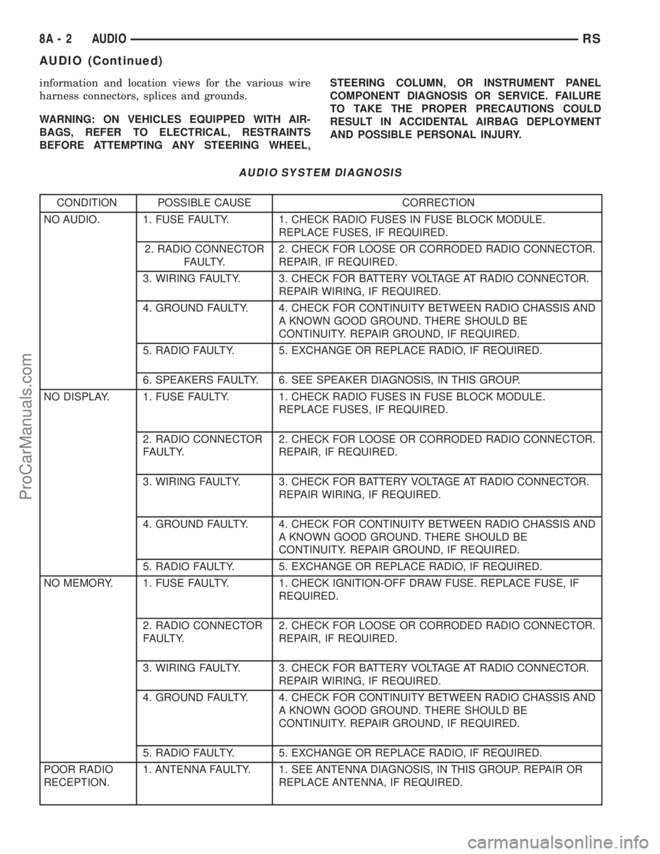
AUDIO SYSTEM DIAGNOSIS
CONDITION POSSIBLE CAUSE CORRECTION
NO AUDIO. 1. FUSE FAULTY. 1. CHECK RADIO FUSES IN FUSE BLOCK MODULE.
REPLACE FUSES, IF REQUIRED.
2. RADIO CONNECTOR
FAULTY.2. CHECK FOR LOOSE OR CORRODED RADIO CONNECTOR.
REPAIR, IF REQUIRED.
3. WIRING FAULTY. 3. CHECK FOR BATTERY VOLTAGE AT RADIO CONNECTOR.
REPAIR WIRING, IF REQUIRED.
4. GROUND FAULTY. 4. CHECK FOR CONTINUITY BETWEEN RADIO CHASSIS AND
A KNOWN GOOD GROUND. THERE SHOULD BE
CONTINUITY. REPAIR GROUND, IF REQUIRED.
5. RADIO FAULTY. 5. EXCHANGE OR REPLACE RADIO, IF REQUIRED.
6. SPEAKERS FAULTY. 6. SEE SPEAKER DIAGNOSIS, IN THIS GROUP.
NO DISPLAY. 1. FUSE FAULTY. 1. CHECK RADIO FUSES IN FUSE BLOCK MODULE.
REPLACE FUSES, IF REQUIRED.
2. RADIO CONNECTOR
FAULTY.2. CHECK FOR LOOSE OR CORRODED RADIO CONNECTOR.
REPAIR, IF REQUIRED.
3. WIRING FAULTY. 3. CHECK FOR BATTERY VOLTAGE AT RADIO CONNECTOR.
REPAIR WIRING, IF REQUIRED.
4. GROUND FAULTY. 4. CHECK FOR CONTINUITY BETWEEN RADIO CHASSIS AND
A KNOWN GOOD GROUND. THERE SHOULD BE
CONTINUITY. REPAIR GROUND, IF REQUIRED.
5. RADIO FAULTY. 5. EXCHANGE OR REPLACE RADIO, IF REQUIRED.
NO MEMORY. 1. FUSE FAULTY. 1. CHECK IGNITION-OFF DRAW FUSE. REPLACE FUSE, IF
REQUIRED.
2. RADIO CONNECTOR
FAULTY.2. CHECK FOR LOOSE OR CORRODED RADIO CONNECTOR.
REPAIR, IF REQUIRED.
3. WIRING FAULTY. 3. CHECK FOR BATTERY VOLTAGE AT RADIO CONNECTOR.
REPAIR WIRING, IF REQUIRED.
4. GROUND FAULTY. 4. CHECK FOR CONTINUITY BETWEEN RADIO CHASSIS AND
A KNOWN GOOD GROUND. THERE SHOULD BE
CONTINUITY. REPAIR GROUND, IF REQUIRED.
5. RADIO FAULTY. 5. EXCHANGE OR REPLACE RADIO, IF REQUIRED.
POOR RADIO
RECEPTION.1. ANTENNA FAULTY. 1. SEE ANTENNA DIAGNOSIS, IN THIS GROUP. REPAIR OR
REPLACE ANTENNA, IF REQUIRED.
8A - 2 AUDIORS
AUDIO (Continued)
ProCarManuals.com
Page 322 of 2399

CONDITION POSSIBLE CAUSE CORRECTION
2. GROUND FAULTY. 2. CHECK FOR CONTINUITY BETWEEN RADIO CHASSIS AND
A KNOWN GOOD GROUND. THERE SHOULD BE
CONTINUITY. REPAIR GROUND, IF REQUIRED.
3. RADIO FAULTY. 3. EXCHANGE OR REPLACE RADIO, IF REQUIRED.
4. POOR ANTENNA
CONNECTION AT
RADIO OR IN LINE.4. SEAT CONNECTOR.
NO/POOR TAPE
OPERATION.1. FAULTY TAPE. 1. INSERT KNOWN GOOD TAPE AND TEST OPERATION.
2. FOREIGN OBJECTS
BEHIND TAPE DOOR.2. REMOVE FOREIGN OBJECTS AND TEST OPERATION.
3. DIRTY CASSETTE
TAPE HEAD.3. CLEAN HEAD WITH MOPAR CASSETTE HEAD CLEANER.
4. FAULTY TAPE DECK. 4. EXCHANGE OR REPLACE RADIO, IF REQUIRED.
NO COMPACT
DISC
OPERATION1. FAULTY CD. 1. INSERT KNOWN GOOD CD AND TEST OPERATION.
2. FOREIGN MATERIAL
ON CD.2. CLEAN CD AND TEST OPERATION.
3. CONDENSATION ON
CD OR OPTICS.3. ALLOW TEMPERATURE OF VEHICLE INTERIOR TO
STABILIZE AND TEST OPERATION.
4. FAULTY CD PLAYER. 4. EXCHANGE OR REPLACE RADIO, IF REQUIRED.
HEADPHONES
WILL NOT HOLD
A CHANNEL OR
HAVE STATIC1. WEAK BATTERIES IN
THE HEADPHONES.1. REPLACE BATTERIES.
2. CLOSENESS TO
RADIO TRANSMITTER
SUCH AS A RADIO
TOWER, AIRPORT
TRANSMITTER OR
SOME MOBILE
RADIOS.2. MOVE TO AN AREA AWAY FREE FROM THESE
CONDITIONS.
REMOTE
CONTROL
INOPERATIVE1. WEAK BATTERIES IN
THE REMOTE
CONTROL.1. REPLACE BATTERIES.
2. OPERATION
CONSTRAINT OF
SYSTEM2. MAKE SURE THAT REAR AUDIO IS IN A DIFFERENT MODE
THAN FRONT SPEAKERS. REMOTE CONTROL WILL NOT
WORK WHEN BOTH ARE IN THE SAME MODE.
RSAUDIO8A-3
AUDIO (Continued)
ProCarManuals.com
Page 323 of 2399
ANTENNA BODY AND CABLE
DESCRIPTION
All models use a fixed-length stainless steel rod-
type antenna mast, installed at the right front fender
of the vehicle. The antenna mast is connected to the
center wire of the coaxial antenna cable, and is not
grounded to any part of the vehicle.
OPERATION
To minimize static, the antenna base must have a
good ground. The coaxial antenna cable shield (the
outer wire mesh of the cable) is grounded to the
antenna base and the radio chassis.
The antenna coaxial cable has an additional dis-
connect, located near the right end of the instrument
panel. This additional disconnect allows the instru-
ment panel assembly to be removed and installed
without removing the radio.
The factory-installed Electronically Tuned Radios
(ETRs) automatically compensate for radio antenna
trim. Therefore, no antenna trimmer adjustment is
required or possible when replacing the receiver or
the antenna.
DIAGNOSIS AND TESTING - ANTENNA BODY
AND CABLE
WARNING: ON VEHICLES EQUIPPED WITH AIR-
BAGS, REFER TO ELECTRICAL, RESTRAINTS
BEFORE ATTEMPTING ANY STEERING WHEEL,
STEERING COLUMN, OR INSTRUMENT PANEL
COMPONENT DIAGNOSIS OR SERVICE. FAILURE
TO TAKE THE PROPER PRECAUTIONS COULD
RESULT IN ACCIDENTAL AIRBAG DEPLOYMENT
AND POSSIBLE PERSONAL INJURY.
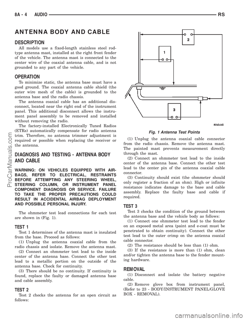
The ohmmeter test lead connections for each test
are shown in (Fig. 1).
TEST 1
Test 1 determines of the antenna mast is insulated
from the base. Proceed as follows:
(1) Unplug the antenna coaxial cable from the
radio chassis and isolate. Remove the antenna mast.
(2) Connect an ohmmeter test lead to the inside
center of the antenna base. Connect the other test
lead to a metallic portion on the outside of the
antenna base. Check for continuity.
(3) There should be no continuity. If continuity is
found, replace the faulty or damaged antenna base
and cable assembly.
TEST 2
Test 2 checks the antenna for an open circuit as
follows:(1) Unplug the antenna coaxial cable connector
from the radio chassis. Remove the antenna mast.
The painted mast prevents measurement directly
through the mast.
(2) Connect an ohmmeter test lead to the inside
center of the antenna base. Connect the other test
lead to the center pin of the antenna coaxial cable
connector.
(3) Continuity should exist (the ohmmeter should
only register a fraction of an ohm). High or infinite
resistance indicates damage to the base and cable
assembly. Replace the faulty base and cable if
required.
TEST 3
Test 3 checks the condition of the ground between
the antenna base and the vehicle body as follows:
(1) Connect one ohmmeter test lead to the fender
on an exposed metal area (paint and e-coat must be
penetrated to obtain continuity). Connect the other
test lead to the outer crimp on the antenna coaxial
cable connector.
(2) The resistance should be less than (1) ohm.
(3) If the resistance is more than (1) ohm, clean
and/or tighten the antenna base to the fender mount-
ing hardware.
REMOVAL
(1) Disconnect and isolate the battery negative
cable.
(2) Remove glove box from instrument panel,
(Refer to 23 - BODY/INSTRUMENT PANEL/GLOVE
BOX - REMOVAL).
Fig. 1 Antenna Test Points
8A - 4 AUDIORS
ProCarManuals.com
Page 325 of 2399
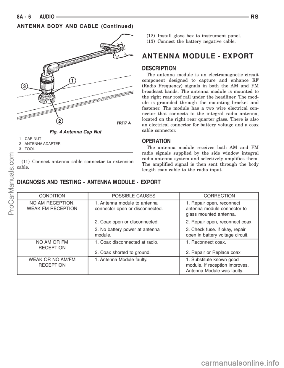
(11) Connect antenna cable connector to extension
cable.(12) Install glove box to instrument panel.
(13) Connect the battery negative cable.
ANTENNA MODULE - EXPORT
DESCRIPTION
The antenna module is an electromagnetic circuit
component designed to capture and enhance RF
(Radio Frequency) signals in both the AM and FM
broadcast bands. The antenna module is mounted to
the right rear roof rail under the headliner. The mod-
ule is grounded through the mounting bracket and
fastener. The module has a two wire electrical con-
nector that connects to the integral radio antenna,
located on the right rear quarter glass. There is also
an electrical connector for battery voltage and a coax
cable connector.
OPERATION
The antenna module receives both AM and FM
radio signals supplied by the side window integral
radio antenna system and selectively amplifies them.
The amplified signal is then sent through the body
length coax cable to the radio input.
DIAGNOSIS AND TESTING - ANTENNA MODULE - EXPORT
CONDITION POSSIBLE CAUSES CORRECTION
NO AM RECEPTION,
WEAK FM RECEPTION1. Antenna module to antenna
connector open or disconnected.1. Repair open, reconnect
antenna module connector to
glass mounted antenna.
2. Coax open or disconnected. 2. Repair open, reconnect coax.
3. No battery power at antenna
module.3. Check fuse. if okay, repair
open in battery voltage circuit.
NO AM OR FM
RECEPTION1. Coax disconnected at radio. 1. Reconnect coax.
2. Coax shorted to ground. 2. Repair or Replace coax
WEAK OR NO AM/FM
RECEPTION1. Antenna Module faulty. 1. Substitute known good
module. If reception improves,
Antenna Module was faulty.
Fig. 4 Antenna Cap Nut
1 - CAP NUT
2 - ANTENNA ADAPTER
3 - TOOL
8A - 6 AUDIORS
ANTENNA BODY AND CABLE (Continued)
ProCarManuals.com
Page 348 of 2399
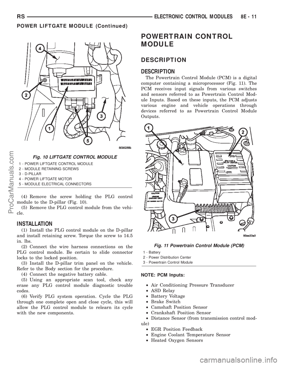
(4) Remove the screw holding the PLG control
module to the D-pillar (Fig. 10).
(5) Remove the PLG control module from the vehi-
cle.
INSTALLATION
(1) Install the PLG control module on the D-pillar
and install retaining screw. Torque the screw to 14.5
in. lbs.
(2) Connect the wire harness connections on the
PLG control module. Be certain to slide connector
locks to the locked position.
(3) Install the D-pillar trim panel on the vehicle.
Refer to the Body section for the procedure.
(4) Connect the negative battery cable.
(5) Using an appropriate scan tool, check any
erase any PLG control module diagnostic trouble
codes.
(6) Verify PLG system operation. Cycle the PLG
through one complete open and close cycle, this will
allow the PLG control module to relearn its cycle
with the new components.
POWERTRAIN CONTROL
MODULE
DESCRIPTION
DESCRIPTION
The Powertrain Control Module (PCM) is a digital
computer containing a microprocessor (Fig. 11). The
PCM receives input signals from various switches
and sensors referred to as Powertrain Control Mod-
ule Inputs. Based on these inputs, the PCM adjusts
various engine and vehicle operations through
devices referred to as Powertrain Control Module
Outputs.
NOTE: PCM Inputs:
²Air Conditioning Pressure Transducer
²ASD Relay
²Battery Voltage
²Brake Switch
²Camshaft Position Sensor
²Crankshaft Position Sensor
²Distance Sensor (from transmission control mod-
ule)
²EGR Position Feedback
²Engine Coolant Temperature Sensor
²Heated Oxygen Sensors
Fig. 10 LIFTGATE CONTROL MODULE
1 - POWER LIFTGATE CONTROL MODULE
2 - MODULE RETAINING SCREWS
3 - D-PILLAR
4 - POWER LIFTGATE MOTOR
5 - MODULE ELECTRICAL CONNECTORS
Fig. 11 Powertrain Control Module (PCM)
1 - Battery
2 - Power Distribution Center
3 - Powertrain Control Module
RSELECTRONIC CONTROL MODULES8E-11
POWER LIFTGATE MODULE (Continued)
ProCarManuals.com
Page 349 of 2399
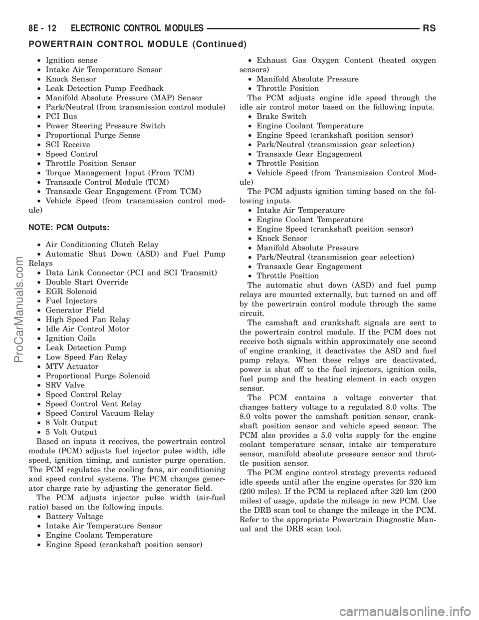
²Ignition sense
²Intake Air Temperature Sensor
²Knock Sensor
²Leak Detection Pump Feedback
²Manifold Absolute Pressure (MAP) Sensor
²Park/Neutral (from transmission control module)
²PCI Bus
²Power Steering Pressure Switch
²Proportional Purge Sense
²SCI Receive
²Speed Control
²Throttle Position Sensor
²Torque Management Input (From TCM)
²Transaxle Control Module (TCM)
²Transaxle Gear Engagement (From TCM)
²Vehicle Speed (from transmission control mod-
ule)
NOTE: PCM Outputs:
²Air Conditioning Clutch Relay
²Automatic Shut Down (ASD) and Fuel Pump
Relays
²Data Link Connector (PCI and SCI Transmit)
²Double Start Override
²EGR Solenoid
²Fuel Injectors
²Generator Field
²High Speed Fan Relay
²Idle Air Control Motor
²Ignition Coils
²Leak Detection Pump
²Low Speed Fan Relay
²MTV Actuator
²Proportional Purge Solenoid
²SRV Valve
²Speed Control Relay
²Speed Control Vent Relay
²Speed Control Vacuum Relay
²8 Volt Output
²5 Volt Output
Based on inputs it receives, the powertrain control
module (PCM) adjusts fuel injector pulse width, idle
speed, ignition timing, and canister purge operation.
The PCM regulates the cooling fans, air conditioning
and speed control systems. The PCM changes gener-
ator charge rate by adjusting the generator field.
The PCM adjusts injector pulse width (air-fuel
ratio) based on the following inputs.
²Battery Voltage
²Intake Air Temperature Sensor
²Engine Coolant Temperature
²Engine Speed (crankshaft position sensor)²Exhaust Gas Oxygen Content (heated oxygen
sensors)
²Manifold Absolute Pressure
²Throttle Position
The PCM adjusts engine idle speed through the
idle air control motor based on the following inputs.
²Brake Switch
²Engine Coolant Temperature
²Engine Speed (crankshaft position sensor)
²Park/Neutral (transmission gear selection)
²Transaxle Gear Engagement
²Throttle Position
²Vehicle Speed (from Transmission Control Mod-
ule)
The PCM adjusts ignition timing based on the fol-
lowing inputs.
²Intake Air Temperature
²Engine Coolant Temperature
²Engine Speed (crankshaft position sensor)
²Knock Sensor
²Manifold Absolute Pressure
²Park/Neutral (transmission gear selection)
²Transaxle Gear Engagement
²Throttle Position
The automatic shut down (ASD) and fuel pump
relays are mounted externally, but turned on and off
by the powertrain control module through the same
circuit.
The camshaft and crankshaft signals are sent to
the powertrain control module. If the PCM does not
receive both signals within approximately one second
of engine cranking, it deactivates the ASD and fuel
pump relays. When these relays are deactivated,
power is shut off to the fuel injectors, ignition coils,
fuel pump and the heating element in each oxygen
sensor.
The PCM contains a voltage converter that
changes battery voltage to a regulated 8.0 volts. The
8.0 volts power the camshaft position sensor, crank-
shaft position sensor and vehicle speed sensor. The
PCM also provides a 5.0 volts supply for the engine
coolant temperature sensor, intake air temperature
sensor, manifold absolute pressure sensor and throt-
tle position sensor.
The PCM engine control strategy prevents reduced
idle speeds until after the engine operates for 320 km
(200 miles). If the PCM is replaced after 320 km (200
miles) of usage, update the mileage in new PCM. Use
the DRB scan tool to change the mileage in the PCM.
Refer to the appropriate Powertrain Diagnostic Man-
ual and the DRB scan tool.
8E - 12 ELECTRONIC CONTROL MODULESRS
POWERTRAIN CONTROL MODULE (Continued)
ProCarManuals.com
Page 351 of 2399

(M) Check Engine Lamp (MIL) will illuminate during engine operation if this Diagnostic Trouble Code was recorded.
(G) Generator Lamp Illuminated
GENERIC
SCAN TOOL
CODEDRB SCAN TOOL DISPLAY DESCRIPTION OF DIAGNOSTIC TROUBLE CODE
P0106 (M) Barometric Pressure Out of Range MAP sensor input voltage out of an acceptable range
detected during reading of barometric pressure at key-on.
P0107 (M) Map Sensor Voltage Too Low MAP sensor input below minimum acceptable voltage.
P0108 (M) Map Sensor Voltage Too High MAP sensor input above maximum acceptable voltage.
P0110 Intake Air Temp Sensor Stuck A rationality error has been detected for the intake air temp.
sensor.
P0111 (M) Intake Air Temp Sensor Performance Intake Air change less than 3É C in 200 Miles
P0112 (M) Intake Air Temp Sensor Voltage Low Intake air (charge) temperature sensor input below the
minimum acceptable voltage.
P0113 (M) Intake Air Temp Sensor Voltage High Intake air (charge) temperature sensor input above the
maximum acceptable voltage.
P0116 Engine Coolant Temp Performance A rationality error has been detected in the coolant temp
sensor.
P0117 (M) ECT Sensor Voltage Too Low Engine coolant temperature sensor input below the minimum
acceptable voltage.
P0118 (M) ECT Sensor Voltage Too High Engine coolant temperature sensor input above the
maximum acceptable voltage.
P0121 (M) TPS Voltage Does Not Agree With
MAPTPS signal does not correlate to MAP sensor signal.
P0122 (M) Throttle Position Sensor Voltage Low Throttle position sensor input below the acceptable voltage
range.
P0123 (M) Throttle Position Sensor Voltage High Throttle position sensor input above the maximum
acceptable voltage.
P0125 (M) Engine Coolant Temp Not Reached Time to enter Closed Loop Operation (Fuel Control) is
excessive.
P0128 Thermostat Rationality A rationality error has been detected for the thermostat
P0129 Barometic Pressure Out-of-Range low MAP sensor input voltage out of an acceptable range
detected during reading of barometric pressure.
P0130 1/1 O2 Sensor Heater Relay Circuit An open or shorted condition detected in the ASD or CNG
shutoff relay control ckt.
P0131 (M) 1/1 O2 Sensor Shorted To Ground Oxygen sensor input voltage maintained below normal
operating range.
P0132 (M) 1/1 O2 Sensor Shorted To Voltage Oxygen sensor input voltage maintained above normal
operating range.
P0133 (M) 1/1 O2 Sensor Slow Response Oxygen sensor response slower than minimum required
switching frequency.
P0134 (M) 1/1 O2 Sensor Stays at Center Neither rich or lean condition is detected from the oxygen
sensor input.
P0135 (M) 1/1 O2 Sensor Heater Failure Oxygen sensor heater element malfunction.
P0136 1/2 O2 Sensor Heater Relay Circuit An open or shorted condition detected in the ASD or CNG
shutoff relay control ckt.
P0137 (M) 1/2 O2 Sensor Shorted To Ground Oxygen sensor input voltage maintained below normal
operating range.
8E - 14 ELECTRONIC CONTROL MODULESRS
POWERTRAIN CONTROL MODULE (Continued)
ProCarManuals.com
Page 352 of 2399

(M) Check Engine Lamp (MIL) will illuminate during engine operation if this Diagnostic Trouble Code was recorded.
(G) Generator Lamp Illuminated
GENERIC
SCAN TOOL
CODEDRB SCAN TOOL DISPLAY DESCRIPTION OF DIAGNOSTIC TROUBLE CODE
P0138 (M) 1/2 O2 Sensor Shorted To Voltage Oxygen sensor input voltage maintained above normal
operating range.
P0139 (M) 1/2 O2 Sensor Slow Response Oxygen sensor response not as expected.
P0140 (M) 1/2 O2 Sensor Stays at Center Neither rich or lean condition is detected from the oxygen
sensor.
P0141 (M) 1/2 O2 Sensor Heater Failure Oxygen sensor heater element malfunction.
P0143 1/3 O2 Sensor Shorted To Ground Oxygen sensor input voltage maintained below normal
operating range.
P0144 1/3 O2 Sensor Shorted To Voltage Oxygen sensor input voltage maintained above normal
operating range.
P0145 1/3 O2 Sensor Slow Response Oxygen sensor response slower than minimum required
switching frequency.
P0146 1/3 O2 Sensor Stays at Center Neither rich or lean condition is detected from the oxygen
sensor.
P0147 1/3 O2 Sensor Heater Failure Oxygen sensor heater element malfunction.
P0151 (M) 2/1 O2 Sensor Shorted To Ground Oxygen sensor input voltage maintained below normal
operating range.
P0152 (M) 2/1 O2 Sensor Shorted To Voltage Oxygen sensor input voltage sustained above normal
operating range.
P0153 (M) 2/1 O2 Sensor Slow Response Oxygen sensor response slower than minimum required
switching frequency.
P0154 (M) 2/1 O2 Sensor Stays at Center Neither rich or lean condition is detected from the oxygen
sensor.
P0155 (M) 2/1 O2 Sensor Heater Failure Oxygen sensor heater element malfunction.
P0157 (M) 2/2 O2 Sensor Shorted To Ground Oxygen sensor input voltage maintained below normal
operating range.
P0158 (M) 2/2 O2 Sensor Shorted To Voltage Oxygen sensor input voltage maintained above normal
operating range.
P0159 2/2 O2 Sensor Slow Response Oxygen sensor response slower than minimum required
switching frequency.
P0160 (M) 2/2 O2 Sensor Stays at Center Neither rich or lean condition is detected from the oxygen
sensor.
P0161 (M) 2/2 O2 Sensor Heater Failure Oxygen sensor heater element malfunction.
P0165 Starter Relay Circuit
P0171 (M) 1/1 Fuel System Lean A lean air/fuel mixture has been indicated by an abnormally
rich correction factor.
P0172 (M) 1/1 Fuel System Rich A rich air/fuel mixture has been indicated by an abnormally
lean correction factor.
P0174 (M) 2/1 Fuel System Lean A lean air/fuel mixture has been indicated by an abnormally
rich correction factor.
P0175 (M) 2/1 Fuel System Rich A rich air/fuel mixture has been indicated by an abnormally
lean correction factor.
P0176 Flex Fuel Calibration Signal No calibration voltage present from flex fuel sensor.
RSELECTRONIC CONTROL MODULES8E-15
POWERTRAIN CONTROL MODULE (Continued)
ProCarManuals.com
Page 354 of 2399
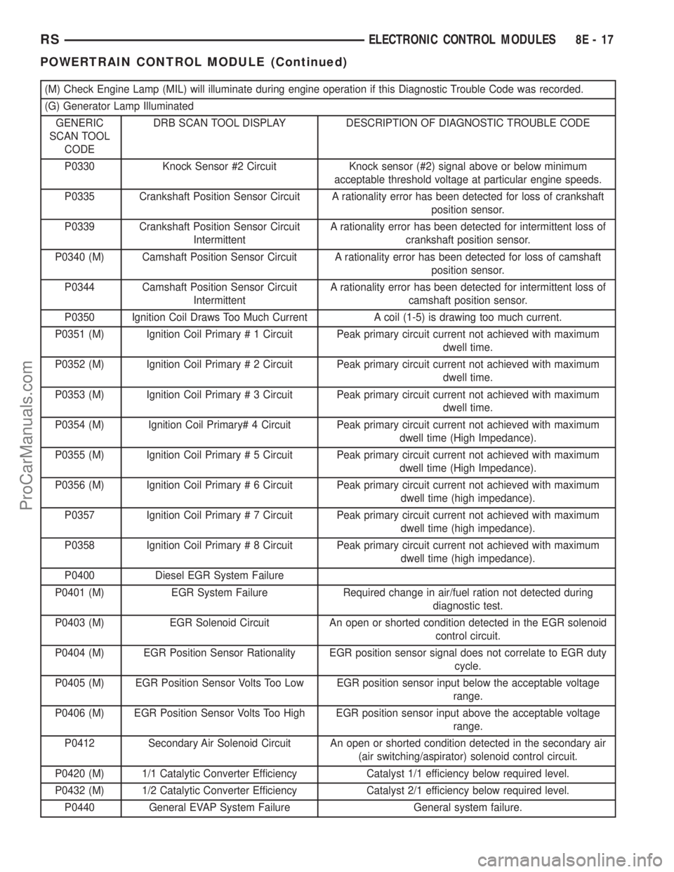
(M) Check Engine Lamp (MIL) will illuminate during engine operation if this Diagnostic Trouble Code was recorded.
(G) Generator Lamp Illuminated
GENERIC
SCAN TOOL
CODEDRB SCAN TOOL DISPLAY DESCRIPTION OF DIAGNOSTIC TROUBLE CODE
P0330 Knock Sensor #2 Circuit Knock sensor (#2) signal above or below minimum
acceptable threshold voltage at particular engine speeds.
P0335 Crankshaft Position Sensor Circuit A rationality error has been detected for loss of crankshaft
position sensor.
P0339 Crankshaft Position Sensor Circuit
IntermittentA rationality error has been detected for intermittent loss of
crankshaft position sensor.
P0340 (M) Camshaft Position Sensor Circuit A rationality error has been detected for loss of camshaft
position sensor.
P0344 Camshaft Position Sensor Circuit
IntermittentA rationality error has been detected for intermittent loss of
camshaft position sensor.
P0350 Ignition Coil Draws Too Much Current A coil (1-5) is drawing too much current.
P0351 (M) Ignition Coil Primary # 1 Circuit Peak primary circuit current not achieved with maximum
dwell time.
P0352 (M) Ignition Coil Primary # 2 Circuit Peak primary circuit current not achieved with maximum
dwell time.
P0353 (M) Ignition Coil Primary # 3 Circuit Peak primary circuit current not achieved with maximum
dwell time.
P0354 (M) Ignition Coil Primary# 4 Circuit Peak primary circuit current not achieved with maximum
dwell time (High Impedance).
P0355 (M) Ignition Coil Primary # 5 Circuit Peak primary circuit current not achieved with maximum
dwell time (High Impedance).
P0356 (M) Ignition Coil Primary # 6 Circuit Peak primary circuit current not achieved with maximum
dwell time (high impedance).
P0357 Ignition Coil Primary # 7 Circuit Peak primary circuit current not achieved with maximum
dwell time (high impedance).
P0358 Ignition Coil Primary # 8 Circuit Peak primary circuit current not achieved with maximum
dwell time (high impedance).
P0400 Diesel EGR System Failure
P0401 (M) EGR System Failure Required change in air/fuel ration not detected during
diagnostic test.
P0403 (M) EGR Solenoid Circuit An open or shorted condition detected in the EGR solenoid
control circuit.
P0404 (M) EGR Position Sensor Rationality EGR position sensor signal does not correlate to EGR duty
cycle.
P0405 (M) EGR Position Sensor Volts Too Low EGR position sensor input below the acceptable voltage
range.
P0406 (M) EGR Position Sensor Volts Too High EGR position sensor input above the acceptable voltage
range.
P0412 Secondary Air Solenoid Circuit An open or shorted condition detected in the secondary air
(air switching/aspirator) solenoid control circuit.
P0420 (M) 1/1 Catalytic Converter Efficiency Catalyst 1/1 efficiency below required level.
P0432 (M) 1/2 Catalytic Converter Efficiency Catalyst 2/1 efficiency below required level.
P0440 General EVAP System Failure General system failure.
RSELECTRONIC CONTROL MODULES8E-17
POWERTRAIN CONTROL MODULE (Continued)
ProCarManuals.com
Page 355 of 2399

(M) Check Engine Lamp (MIL) will illuminate during engine operation if this Diagnostic Trouble Code was recorded.
(G) Generator Lamp Illuminated
GENERIC
SCAN TOOL
CODEDRB SCAN TOOL DISPLAY DESCRIPTION OF DIAGNOSTIC TROUBLE CODE
P0441 (M) Evap Purge Flow Monitor Insufficient or excessive vapor flow detected during
evaporative emission system operation.
P0442 (M) Evap Leak Monitor 0.040 Leak
DetectedA 0.040 leak has been detected in the evaporative system.
P0443 (M) Evap Purge Solenoid Circuit An open or shorted condition detected in the EVAP purge
solenoid control circuit.
P0452 NVLD Pressure Switch Stuck Closed NVLD pressure switch stuck closed.
P0453 NVLD Pressure Switch Stuck Open NVLD pressure switch stuck open.
P0455 (M) Evap Leak Monitor Large Leak
DetectedA large leak has been detected in the evaporative system.
P0456 (M) Evap Leak Monitor 0.020 Leak
DetectedA 0.020 leak has been detected in the evaporative system.
P0460 Fuel Level Unit No Change Over Miles No movement of fuel level sender detected.
P0461 Fuel Level Unit No Changeover Time No level of fuel level sender detected.
P0462 Fuel Level Sending Unit Volts Too Low Fuel level sensor input below acceptable voltage.
P0463 Fuel Level Sending Unit Volts Too
HighFuel level sensor input above acceptable voltage.
P0480 Low Speed Fan Relay Control Circuit An open or shorted condition detected in the low speed rad.
fan relay control circuit.
P0481 High Speed Fan Relay Control Circuit An open or shorted condition detected in the high speed rad.
fan relay control circuit.
P0498 NVLD Canister Vent Valve Solenoid
Circuit LowA shorted low condition detected in NVLD solenoid circuit.
P0499 NVLD Canister Vent Valve Solenoid
Circuit HighA shorted high condition detected in NVLD solenoid circuit.
P0500 (M) No Vehicle Speed Sensor Signal No vehicle speed sensor signal detected during road load
conditions.
P0501 Vehicle Speed Sensor #1 Performance A rationality error has been detected for no vehicle speed
sensor signal detected during road load conditions.
P0505 (M) Idle Air Control Motor Circuits Replace idle air control motor.
P0508 (M) Idle Air Control Motor Circuit Low Idle Air Control Motor Circuit input below acceptable current
P0509 (M) Idle Air Control Motor Circuit High Idle Air Control Motor Circuit input above acceptable current
P0511 Idle Air Control Valve Solenoid Circuit An open or shorted condition detected in the IAC control
circuit.
P0513 Invalid SKIM Key The engine controller has received an invalid key from the
Smart Key Immobilizer Module.
P0516 Battery Temperature Sensor Low Battery Temp. sensor input below minimum acceptable
voltage.
P0517 Battery Temperature Sensor High Battery Temp. sensor input above maximum acceptable
voltage.
P0519 Idle Speed Performance A rationality error has been detected for target RPM not met
during drive idle condition. Possible Vacuum leak or IAC lost
steps.
8E - 18 ELECTRONIC CONTROL MODULESRS
POWERTRAIN CONTROL MODULE (Continued)
ProCarManuals.com