display CHRYSLER VOYAGER 2002 Workshop Manual
[x] Cancel search | Manufacturer: CHRYSLER, Model Year: 2002, Model line: VOYAGER, Model: CHRYSLER VOYAGER 2002Pages: 2399, PDF Size: 57.96 MB
Page 536 of 2399
nications and the BCM. If the brightness level is
improper check the J1850 Data Bus circuit.
The DRB IIItis recommended for checking the
J1850 Data Bus circuit and the BCM. Perform the
EVIC self diagnosis before replacing the EVIC mod-
ule.
STANDARD PROCEDURE - ELECTRONIC
VEHICLE INFORMATION CENTER
PROGRAMMING
EVIC PROGRAMMING MODE
Some vehicles are equipped with a Electronic Vehi-
cle Information Center (EVIC) equipped overhead
console. The Electronic Vehicle Information Center
(EVIC) provides the vehicle operator with a user
interface, which allows the selection of several
optional customer programmable electronic features
to suit individual preferences. The EVIC must be
placed into its programming mode in order to view or
change the programmable features. To enter the
EVIC programming mode and to view or change the
selected programmable features options, proceed as
follows:
(1) Turn the ignition switch to the On position.
(2) Depress and release the Menu push button.
The first item in the programmable features menu
list will appear in the EVIC display.
(3) Momentarily depress and release the Menu
push button to step through the programmable fea-
tures list. Each programmable feature and its cur-
rently selected option will appear on the EVIC
display in the sequence shown in the Programmable
Features list that follows.
(4) Momentarily depress and release the Step push
button to step through the available options for the
programmable feature being displayed.
(5) The option that last appears in the display
with a programmable feature before exiting the pro-
gramming mode, becomes the newly selected pro-
grammable feature option.
(6) The EVIC exits the programming mode and
returns to its normal operating mode when the C/T
push button is depressed or when the end of the pro-
grammable features menu list is reached, whichever
occurs first.
PROGRAMMABLE FEATURES
NOTE: TIRE PRESSURE MONITORING (TPM) SYS-
TEM INFORMATION IS NOT COVERED IN THIS SEC-
TION OF THE SERVICE MANUAL. REFER TO THE
TIRES/WHEELS SECTION OF THIS MANUAL FOR
DETAILED TPM SYSTEM INFORMATION.²LANGUAGE?- The options include English,
Francaise, Deutsch, Italiana, or Espanol. The default
is English. All EVIC display nomenclature, including
the trip computer functions, warning messages and
the programmable features appear in the selected
language.
²DISPLAY U.S. OR METRIC?- The options
include U.S. and M. The default is U.S. This feature
toggles the trip computer temperature, fuel economy
and odometer display readings between U.S. and
metric units of measure. It also changes the odome-
ter display in the instrument cluster.
²SERVICE INTV. =- The options include from
1000 to 12000 kilometers in 1000 kilometer incre-
ments (2000 to 7500 miles in 500 mile increments).
The default is 12000 kilometers (7500 miles). The
selected distance becomes the interval at which the
Perform Service warning message will be displayed
by the EVIC. If a new distance is selected, a second
programmable feature appears,RESET SERVICE
DISTANCE?- The options include No and Yes. The
default is Yes. When Yes is selected, the accumulated
distance since the last previous Perform Service
warning message will be reset to zero because the
service interval has been changed. When No is
selected, the distance until the next Perform Service
warning message is reduced by the accumulated dis-
tance since the last previous message.
²USE FACTORY SETTINGS?- The options
include Yes and No. The default is Yes. When yes is
selected all the programmable features will return to
there defaults and the rest of the programmable fea-
tures will not be displayed. If No is selected the rest
of the programmable features will be displayed at
there default values. This feature will automatically
return to the Yes default under two conditions. First,
if no programmable features are changed from there
defaults. Second, if all the programmable features
equal there defaults.
²AUTO DOOR LOCKS?- The options include
Yes and No. The default is Yes. When Yes is selected,
all doors and the liftgate lock automatically when
vehicle speed reaches 25 kilometers-per-hour (15
miles-per-hour). If YES is selected, a second program-
mable feature appears,AUTO UNLOCK ON EXIT?
- The options again include Yes and No. The default
is No. When Yes is selected, following each Auto Door
Lock event all doors and the liftgate will automati-
cally unlock when the driver door is opened, if the
vehicle is stopped and the transmission gear selector
is in Park or Neutral. The Auto Door Unlock event
will only occur once following each Auto Door Lock
event.
²REMOTE UNLOCK- The options include
Driver Door 1st and All Doors. The default is Driver
Door 1st. When Diver Door 1st is selected, only the
RSMESSAGE SYSTEMS8M-7
ELECTRONIC VEHICLE INFO CENTER (Continued)
ProCarManuals.com
Page 538 of 2399
NOTE: IF A NEW EVIC MODULE HAS BEEN
INSTALLED, THE COMPASS WILL HAVE TO BE
CALIBRATED AND THE VARIANCE SET. REFER TO
COMPASS VARIATION ADJUSTMENT AND COM-
PASS CALIBRATION IN THE SERVICE PROCE-
DURES SECTION OF THIS GROUP FOR THE
PROCEDURES.
COMPASS/MINI-TRIP
COMPUTER
DESCRIPTION
The Compass Mini-Trip Computer (CMTC) and
Compass Temperature (CT) computer are modules
located in the overhead console. Vehicles are
equipped with either the CMTC or the CT computers
not both. The CMTC is different in the fact that it is
equipped with the mini-trip feature. The CMTC, CT
consists of a electronic control module with a vacuum
fluorescent display (VFD) and function switches. The
CMTC, CT consists of a electronic module that dis-
plays compass, trip computer (CMTC only), and tem-
perature features. Actuating the STEP push button
(CMTC only) will cause the CMTC to change mode of
operation when ignition is ON. Actuating the STEP
push button (CMTC only) will cause the CMTC to
change mode of operation when ignition is ON.
Example:
²Average miles per gallon (ECO)
²Distance to empty (DTE)
²Instant miles per gallon (ECO)
²Trip odometer (ODO)
²Elapsed time (ET)
²Off
Actuating the C/T push button will cause the
CMTC, CT to change to Compass/Temperature dis-
play.
OPERATION
The Compass Mini-Trip Computer (CMTC), Com-
pass Temperature (CT) module in the overhead con-
sole has buttons used to select various functions. The
CMTC, CT selector buttons will not operate until the
ignition is in the RUN position.
When the ignition switch is first turned to the
RUN position the CMTC, CT display;
²Blanks momentarily
²All segments of the VFD will light for one sec-
ond
²Blanks momentarily
²Returns to the last mode setting selected before
the ignition was last switched OFF.
DIAGNOSIS AND TESTING - COMPASS
MINI-TRIP COMPUTER
Compass Mini-Trip Computer (CMTC) and Com-
pass Temperature (CT) data is obtained from the
Body Control Module (BCM) on the J1850 Data Bus
circuit. The CMTC and CT will display dashes (- -)
for any of the screens it did not receive the bus mes-
sages. The label corresponding to the missing infor-
mation will be lit. If no compass mini-trip computer
data is displayed, check the J1850 Data Bus circuit
communications and the BCM. If the brightness level
is improper check the J1850 Data Bus circuit.
The DRB IIItis recommended for checking the
J1850 Data Bus circuit and the BCM. Perform the
CMTC, CT self diagnosis before replacing the CMTC
or CT module.
REMOVAL
(1) Disconnect and isolate the battery negative
cable.
(2) Remove overhead console. Refer to Overhead
Console Removal and Installation in this section(Re-
fer to 8 - ELECTRICAL/OVERHEAD CONSOLE -
REMOVAL).
(3) Remove the screws holding Compass Mini-Trip
Computer module in the overhead console.
(4) Remove CMTC module from console assembly.
INSTALLATION
(1) Position the compass mini-trip computer mod-
ule in the overhead console.
(2) Install the ten screws holding the compass
mini-trip computer module in the overhead console.
(3) Install the overhead console. Refer to Overhead
Console Removal and Installation in this section.
(4) Connect the battery negative cable.
NOTE: If a new module has been installed, the com-
pass will have to be calibrated and the variance set.
Refer to Compass Variation Adjustment and Com-
pass Calibration in the Service Procedures section
of this group for the procedures.
UNIVERSAL TRANSMITTER
DESCRIPTION
On some RS models a Universal Transmitter trans-
ceiver is standard factory-installed equipment. The
universal transmitter transceiver is integral to the
Electronic Vehicle Information Center (EVIC) and the
Compass Mini-Trip Computer (CMTC), which is
located in the overhead console. The only visible com-
ponent of the universal transmitter are the three
transmitter push buttons centered between the mod-
RSMESSAGE SYSTEMS8M-9
ELECTRONIC VEHICLE INFO CENTER (Continued)
ProCarManuals.com
Page 539 of 2399
ules push buttons located just rearward of the dis-
play screen in the overhead console. The three
universal transmitter push buttons are identified
with one, two or three light indicators so that they be
easily identified by sight or by feel.
Each of the three universal transmitter push but-
tons controls an independent radio transmitter chan-
nel. Each of these three channels can be trained to
transmit a different radio frequency signal for the
remote operation of garage door openers, motorized
gate openers, home or office lighting, security sys-
tems or just about any other device that can be
equipped with a radio receiver in the 286 to 399
MegaHertz (MHz) frequency range for remote opera-
tion. The universal transmitter is capable of operat-
ing systems using either rolling code or non-rolling
code technology.
The electronics module displays messages and a
small house-shaped icon with one, two or three dots
corresponding to the three transmitter buttons to
indicate the status of the universal transmitter. The
EVIC messages are:
²Cleared Channels- Indicates that all of the
transmitter codes stored in the universal transmitter
have been successfully cleared.
²Training- Indicates that the universal trans-
mitter is in its transmitter learning mode.
²Trained- Indicates that the universal transmit-
ter has successfully acquired a new transmitter code.
²Transmit- Indicates that a trained universal
transmitter button has been depressed and that the
universal transmitter is transmitting.
The universal transmitter cannot be repaired, and
is available for service only as a unit with the EVIC
or CMTC modules. If any of these components is
faulty or damaged, the complete EVIC or CMTC
module must be replaced.
OPERATION
The universal transmitter operates on a non-
switched source of battery current so the unit will
remain functional, regardless of the ignition switch
position. For more information on the features, pro-
gramming procedures and operation of the universal
transmitter, see the owner's manual in the vehicle
glove box.
DIAGNOSIS AND TESTING - UNIVERSAL
TRANSMITTER
If the universal transmitter is inoperative, but the
Electronic Vehicle Information Center (EVIC) or
Compass Mini-Trip Computer is operating normally,
see the owner's manual in the vehicle glove box for
instructions on training the universal transmitter.
Retrain the universal transmitter with a known good
transmitter as instructed in the owner's manual andtest the universal transmitter operation again. If the
unit is still inoperative, replace the faulty universal
transmitter and EVIC/CMTC module as a unit. If
both the universal transmitter and the EVIC/CMTC
module are inoperative, refer toOverhead Console
Diagnosis and Testingearlier in this group for fur-
ther diagnosis. For complete circuit diagrams, refer
toOverhead Consolein Wiring Diagrams.
AMBIENT TEMP SENSOR
DESCRIPTION
Ambient air temperature is monitored by the over-
head console through ambient temperature messages
received from the Front Control Module (FCM) over
the Programmable Communications Interface (PCI)
J1850 data bus circuit. The FCM receives a hard
wired input from the ambient temperature sensor.
The ambient temperature sensor is a variable resis-
tor mounted to a bracket that is secured with a screw
to the right side of the headlamp mounting module
grille opening, behind the radiator grille and in front
of the engine compartment.
Refer toFront Control Modulein Electronic
Control Modules. For complete circuit diagrams, refer
to the appropriate wiring information. The ambient
temperature sensor cannot be adjusted or repaired
and, if faulty or damaged, it must be replaced.
OPERATION
The ambient temperature sensor is a variable
resistor that operates on a five-volt reference signal
sent to it by the Front Control Module. The resis-
tance in the sensor changes as temperature changes,
changing the temperature sensor signal circuit volt-
age to the Front Control Module. Based upon the
resistance in the sensor, the Front Control Module
senses a specific voltage on the temperature sensor
signal circuit, which it is programmed to correspond
to a specific temperature. The Front Control Module
then sends the proper ambient temperature mes-
sages to the EVIC, CMTC over the PCI J1850 data
bus.
The thermometer function is supported by the
ambient temperature sensor, a wiring circuit, the
Front Control Module, the Programmable Communi-
cations Interface (PCI) data bus, and a portion of the
Electronics module. If any portion of the ambient
temperature sensor circuit fails, the Front Control
Module will self-diagnose the circuit.
The ambient temperature sensor circuit can also be
diagnosed by referring toDiagnosis and Testing -
Ambient Temperature Sensor, and Diagnosis
and Testing - Ambient Temperature Sensor Cir-
cuit. If the temperature sensor and circuit are con-
8M - 10 MESSAGE SYSTEMSRS
UNIVERSAL TRANSMITTER (Continued)
ProCarManuals.com
Page 540 of 2399
firmed to be OK, but the temperature display is
inoperative or incorrect, refer toDiagnosis and
Testing - Overhead Consolein this group. For
complete circuit diagrams, refer to the appropriate
wiring information.
DIAGNOSIS AND TESTING
DIAGNOSIS AND TESTING - AMBIENT
TEMPERATURE SENSOR
(1) Turn the ignition switch to the Off position.
Disconnect and isolate the battery negative cable.
Disconnect the ambient temperature sensor wire har-
ness connector.
(2) Measure the resistance of the ambient temper-
ature sensor. At ±40É C (±40É F), the sensor resis-
tance is 336.6 kilohms. At 60É C (140É F), the sensor
resistance is 2.49 kilohms. The sensor resistance
should read between these two values. If OK, refer to
Diagnosis and Testing - Ambient Temperature
Sensor Circuitin this group. If not OK, replace the
faulty ambient temperature sensor.
DIAGNOSIS AND TESTING - AMBIENT
TEMPERATURE SENSOR CIRCUIT
(1) Turn the ignition switch to the Off position.
Disconnect and isolate the battery negative cable.
Disconnect the ambient temperature sensor wire har-
ness connector and the Front Control Module wire
harness connector.
(2) Connect a jumper wire between the two termi-
nals in the body half of the ambient temperature sen-
sor wire harness connector.
(3) Check for continuity between the sensor return
circuit and the ambient temperature sensor signalcircuit cavities of the Front Control Module wire har-
ness connector. There should be continuity. If OK, go
to Step 4. If not OK, repair the open sensor return
circuit or ambient temperature sensor signal circuit
to the ambient temperature sensor as required.
(4) Remove the jumper wire from the body half of
the ambient temperature sensor wire harness con-
nector. Check for continuity between the sensor
return circuit cavity of the Front Control Module
wire harness connector and a good ground. There
should be no continuity. If OK, go to Step 5. If not
OK, repair the shorted sensor return circuit as
required.
(5) Check for continuity between the ambient tem-
perature sensor signal circuit cavity of the Front
Control Module wire harness connector and a good
ground. There should be no continuity. If OK, refer to
Diagnosis and Testing - Overhead Consolein
this group. If not OK, repair the shorted ambient
temperature sensor signal circuit as required.
REMOVAL
(1) Disconnect and isolate the battery negative
cable.
(2) Raise and support vehicle on safety stands.
(3) From behind front bumper fascia, remove
screw holding sensor to radiator closure panel.
(4) Remove sensor from vehicle.
INSTALLATION
(1) Position the sensor in the vehicle.
(2) From behind the front bumper fascia, install
the screw holding sensor to radiator closure panel.
(3) Connect the battery negative cable.
RSMESSAGE SYSTEMS8M-11
AMBIENT TEMP SENSOR (Continued)
ProCarManuals.com
Page 594 of 2399
²Body Control Module (BCM)- Refer toBody
Control Modulein Electronic Control Modules for
more information.
²Powertrain Control Module (PCM)- Refer to
Powertrain Control Modulein Electronic Control
Modules for more information.
Refer toHeated Seat Systemfor more informa-
tion on the heated seat system. Refer toRemote
Keyless Entry Systemin Power Lock Systems for
more information on the RKE system.
Refer toWiring Diagramsfor complete circuit
diagrams. Following are descriptions, theory of oper-
ation, diagnosis/testing procedures and removal/in-
stallation procedures of the major components in the
memory and power seat systems.
OPERATION
OPERATION - POWER SEAT SYSTEM
The power seat system receives battery current
through fuse #22 in the Intelligent Power Module
and a circuit breaker under the front seats, regard-
less of the ignition switch position.
When a power seat switch control knob or knobs
are actuated, a battery feed and a ground path are
applied through the switch contacts to the appropri-
ate power seat track adjuster motor. The selected
adjuster motor operates to move the seat track
through its drive unit in the selected direction until
the switch is released, or until the travel limit of the
seat track is reached. When the switch is moved in
the opposite direction, the battery feed and ground
path to the motor are reversed through the switch
contacts. This causes the adjuster motor to run in the
opposite direction.
No power seat switch should be held applied in any
direction after the seat track has reached its travel
limit. The power seat track each contain a self-reset-
ting circuit breaker to protect them from overload.
However, consecutive or frequent resetting of the cir-
cuit breaker must not be allowed to continue, or the
motor may be damaged. Refer to the owner's manual
in the vehicle glove box for more information on the
features, use and operation of the power seat system.
OPERATION - MEMORY SYSTEM
The memory system receives battery current
through fuse #22 in the Intelligent Power Module
and the power seat system circuit breaker, located
under each front seat near the rear edge of the seat
cushion pans. The Memory Seat Mirror Module
(MSMM) will drive a maximum of 2 motors at a time
in a given direction. If conflicting directions are
requested, the priority for response will be as follows:
²Seat Track Rearward or Forward²Seat Front Down or Up
²Seat Rear Down or Up
²Recliner Rearward or Forward
The inputs from these switches to the MSMM is a
current limited battery source fed by the MSMM.
This protects the MSMM printed circuit board traces
from acting as fuses. All of these switch contact
inputs to the MSMM are normally closed to ground,
except when actuated.
See the owner's manual in the vehicle glove box for
more information on the features, use and operation
of the memory system. For diagnosis of the MSMM,
the PCI data bus, or the other electronic modules on
the PCI data bus that provide inputs and outputs for
the memory system, the use of a DRBIIItscan tool
and the proper Diagnostic Procedures manual are
recommended.
ELECTRONIC VEHICLE INFORMATION CENTER
The Electronic Vehicle Information Center (EVIC)
serves as the user interface for the memory system.
It displays memory system status messages and pro-
vides the user with the means for enabling and dis-
abling the many customer programmable features
available on the vehicle, including those for the mem-
ory system.
See the owner's manual in the vehicle glove box for
more information on the features, use and operation
of the EVIC. Refer toElectronic Vehicle Informa-
tion Centerin Overhead Console Systems for more
information on the EVIC.
DIAGNOSIS AND TESTING
DIAGNOSIS AND TESTING - POWER SEAT
SYSTEM
Following are tests that will help to diagnose the
hard wired components and circuits of the power seat
system. However, if the vehicle is also equipped with
the optional memory system, these tests may not
prove conclusive in the diagnosis of the driver side
power seat. In order to obtain conclusive testing of
the driver side power seat with the memory system
option, the Programmable Communications Interface
(PCI) data bus network and all of the electronic mod-
ules that provide inputs to, or receive outputs from
the memory system components must be checked.
The most reliable, efficient, and accurate means to
diagnose the driver side power seat with the memory
system option requires the use of a DRB IIItscan
tool and the proper Diagnostic Procedures manual.
The DRB IIItscan tool can provide confirmation that
the PCI data bus is functional, that all of the elec-
tronic modules are sending and receiving the proper
messages on the PCI data bus, and that the memory
RSPOWER SEAT SYSTEM8N-53
POWER SEAT SYSTEM (Continued)
ProCarManuals.com
Page 635 of 2399
SKIM in addition to being cut to match the mechan-
ical coding of the ignition lock cylinder. Refer to Elec-
trical, Vehicle Theft Security, Transponder Key,
Standard Procedure - Transponder Programming.
The Sentry Key's transponder is within the range
of the SKIM's transceiver antenna ring when it is
inserted into the ignition lock cylinder. When the
ignition switch is turned to the ON position, the
SKIM communicates with the Sentry Key via a radio
frequency (RF) signal. The SKIM determines if a
valid key is present based on the information it
receives from the Sentry Key. If a valid key is
detected, that fact is communicated to the PCM via
the PCI bus and the vehicle is allowed to continue
running. If an invalid key is received by the PCM or
no status at all is communicated, the vehicle will
stall after two (2) seconds of running. The indicator
light will be flashing at this point. The Sentry Key's
transponder can not be repaired. If it is faulty or
damaged, it must be replaced.
Common communication problems:
²Two transponder keys too close together.
²Speed Pass too close to transponder key.
Solid indicator that there is a system failure.
²Loss of PCM communication.
²Failed antenna circuit.
STANDARD PROCEDURE - TRANSPONDER
PROGRAMMING
USING A DRB IIITSCAN TOOL
All Sentry Keys included with the vehicle are pre-
programmed to work with the Sentry Key Immobi-
lizer System (SKIS) when it is shipped from the
factory. The Sentry Key Immobilizer Module (SKIM)
can be programmed to recognize up to a total of eight
Sentry Keys. When programming a blank Sentry Key
transponder, the key must first be cut to match the
ignition lock cylinder of the vehicle for which it will
be used. The vehicle's four digit PIN code will be
required to complete this task since you will need it
to enter the Secured Access Mode in the SKIM. The
following steps must be completed using a DRB IIIt
scan tool:
(1) Insert the blank key into the ignition and turn
it to the RUN position.
(2) Using a DRB IIItscan tool, select9Theft
Alarm,99SKIM,99Miscellaneous,9and then9Program
New Key.9
(3) Enter the four digit PIN code using the DRB
IIItscan tool. When programming is completed, the
SKIM will exit Secured Access Mode and the DRB
IIItscan tool will display the results of your attempt
to program the key. One of five distinct results may
be displayed. All five are listed below:
²(Programming Successful(is displayed if the
Sentry Key programming is successful.
²(Learned Key in Ignition(is displayed if the
key in the ignition has already been programmed
into that vehicle's SKIM.
²(Eight Keys Already Learned (At The Maxi-
mum) Programming Not Done(is displayed if
eight keys have already been programmed into the
SKIM. In this case, if a new key needs to be added
due to a lost or defective key, the9Erase All Keys9
command (which requires entering the Secured
Access Mode) has to be performed. Following the
9Erase All Keys9command, all keys that will be used
to operate the vehicleMUSTbe reprogrammed to
the SKIM.
²(Programming Not Attempted(is displayed
after an9Erase All Keys9function is executed.
²(Programming Key Failed(is displayed if fur-
ther diagnosis is required.
To learn additional keys, turn the ignition OFF,
remove the learned key, insert the next new blank
key, and repeat the steps from the beginning.
ªCUSTOMER LEARNº MODE
This feature is only available on domestic vehicles
or those which have a U.S. country code designator.
This procedure requires access to at least two valid
Sentry Keys. If two valid Sentry Keys are not avail-
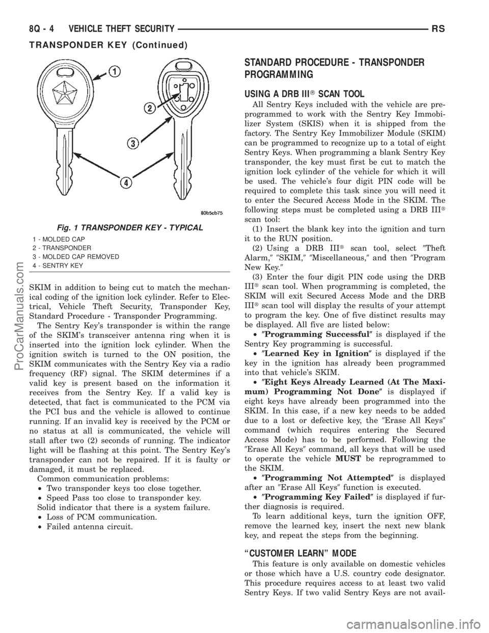
Fig. 1 TRANSPONDER KEY - TYPICAL
1 - MOLDED CAP
2 - TRANSPONDER
3 - MOLDED CAP REMOVED
4 - SENTRY KEY
8Q - 4 VEHICLE THEFT SECURITYRS
TRANSPONDER KEY (Continued)
ProCarManuals.com
Page 1378 of 2399
CYLINDER HEAD
STANDARD PROCEDURE
STANDARD PROCEDURE - VALVE SERVICE
This procedure is done with the engine cylinder
head removed from the block.
DISASSEMBLY
(1) Remove the engine cylinder head from the cyl-
inder block. Refer to cylinder head removal and
installation in this section.
(2) Use Valve Spring Compressor Tool and com-
press each valve spring.
(3) Remove the valve locks, retainers, and springs.
(4) Use an Arkansas smooth stone or a jewelers
file to remove any burrs on the top of the valve stem,
especially around the groove for the locks.
(5) Remove the valves, and place them in a rack in
the same order as removed.
VALVE CLEANING
(1) Clean all carbon deposits from the combustion
chambers, valve ports, valve stems, valve stem
guides and head.
(2) Clean all grime and gasket material from the
engine cylinder head machined gasket surface.
INSPECTION
(1) Inspect for cracks in the combustion chambers
and valve ports.
(2) Inspect for cracks on the exhaust seat.
(3) Inspect for cracks in the gasket surface at each
coolant passage.
(4) Inspect valves for burned, cracked or warped
heads.
(5) Inspect for scuffed or bent valve stems.
(6) Replace valves displaying any damage.
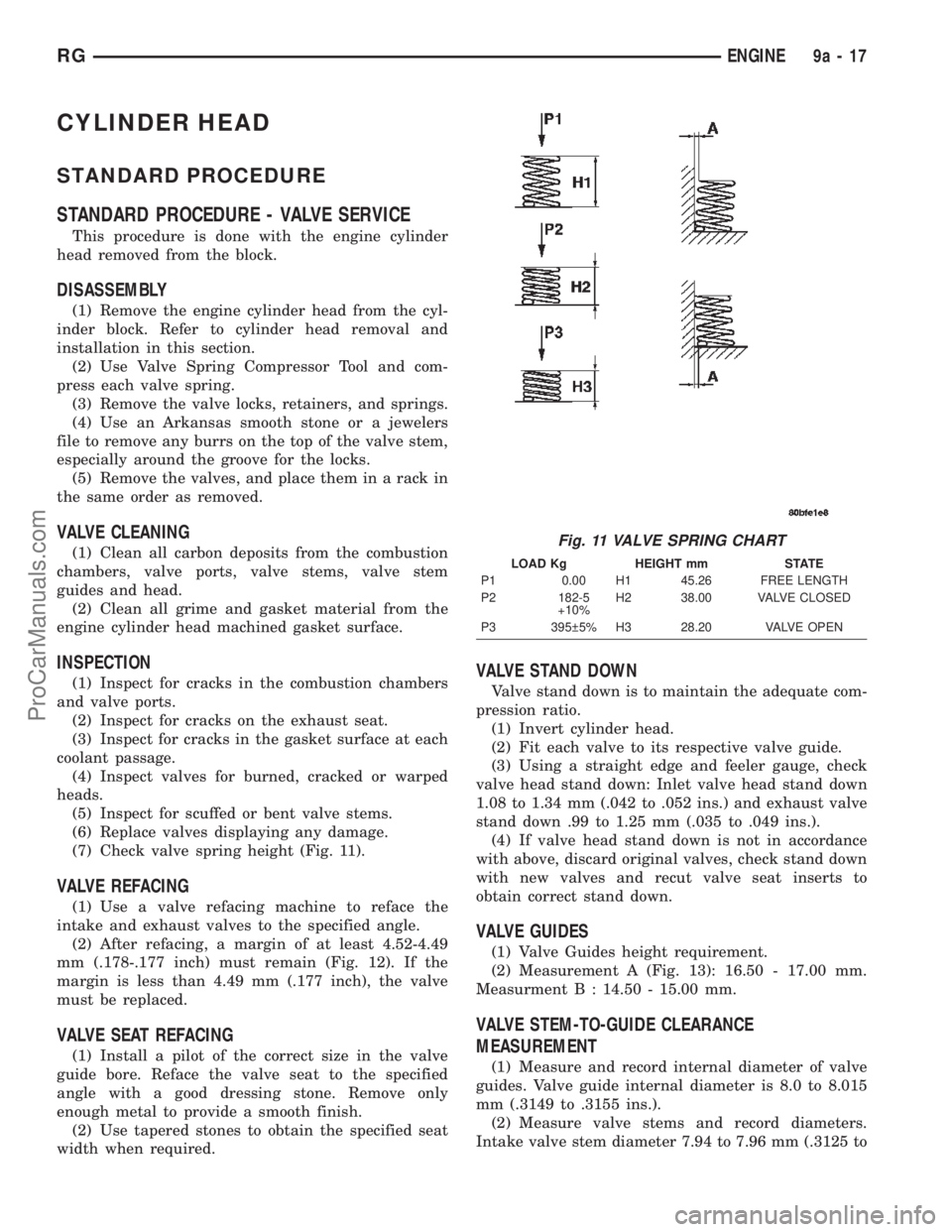
(7) Check valve spring height (Fig. 11).
VALVE REFACING
(1) Use a valve refacing machine to reface the
intake and exhaust valves to the specified angle.
(2) After refacing, a margin of at least 4.52-4.49
mm (.178-.177 inch) must remain (Fig. 12). If the
margin is less than 4.49 mm (.177 inch), the valve
must be replaced.
VALVE SEAT REFACING
(1) Install a pilot of the correct size in the valve
guide bore. Reface the valve seat to the specified
angle with a good dressing stone. Remove only
enough metal to provide a smooth finish.
(2) Use tapered stones to obtain the specified seat
width when required.
VALVE STAND DOWN
Valve stand down is to maintain the adequate com-
pression ratio.
(1) Invert cylinder head.
(2) Fit each valve to its respective valve guide.
(3) Using a straight edge and feeler gauge, check
valve head stand down: Inlet valve head stand down
1.08 to 1.34 mm (.042 to .052 ins.) and exhaust valve
stand down .99 to 1.25 mm (.035 to .049 ins.).
(4) If valve head stand down is not in accordance
with above, discard original valves, check stand down
with new valves and recut valve seat inserts to
obtain correct stand down.
VALVE GUIDES
(1) Valve Guides height requirement.
(2) Measurement A (Fig. 13): 16.50 - 17.00 mm.
Measurment B : 14.50 - 15.00 mm.
VALVE STEM-TO-GUIDE CLEARANCE
MEASUREMENT
(1) Measure and record internal diameter of valve
guides. Valve guide internal diameter is 8.0 to 8.015
mm (.3149 to .3155 ins.).
(2) Measure valve stems and record diameters.
Intake valve stem diameter 7.94 to 7.96 mm (.3125 to
Fig. 11 VALVE SPRING CHART
LOAD Kg HEIGHT mm STATE
P1 0.00 H1 45.26 FREE LENGTH
P2 182-5
+10%H2 38.00 VALVE CLOSED
P3 395 5% H3 28.20 VALVE OPEN
RGENGINE9a-17
ProCarManuals.com
Page 1426 of 2399
(1) Disconnect and remove the upstream (before
catalytic converter) oxygen sensor. (Refer to 14 -
FUEL SYSTEM/FUEL INJECTION/O2 SENSOR -
REMOVAL)
(2) Install the Exhaust Back Pressure Fitting
Adaptor CH8519.
(3) Connect the Low Pressure Sensor (15 psi)
CH7063 to the back pressure fitting.
(4) Following the PEP module instruction manual,
connect all required cables to the DRB IIItand PEP
module. Select the available menu options on the
DRBIIItdisplay screen for using the digital pressure
gauge function.
(5) Apply the park brake and start the engine.
(6) With transmission in Park or Neutral, raise
engine speed to 2000 RPM. Monitor the pressure
readings on the DRBIIIt. Back pressure should not
exceed specified limit. Refer to specification in table
below EXHAUST BACK PRESSURE LIMITS .
NOTE: For applications with dual catalytic convert-
ers, repeat test on opposite converter using the
previous steps.
(7) If pressure exceeds maximum limits, inspect
exhaust system for restricted component. For further
catalytic converter inspection procedures, (Refer to 11
- EXHAUST SYSTEM/CATALYTIC CONVERTER -
INSPECTION). Replace component(s) as necessary.
EXHAUST BACK PRESSURE LIMITS
Exhaust Back Pressure Limit (Max)
Vehicle in Park/Neutral
(no load) RPM3.45 Kpa (0.5 psi)
INSPECTION
Inspect the exhaust pipes, catalytic converters,
muffler, and resonators for cracked joints, broken
welds and corrosion damage that would result in a
leaking exhaust system. Inspect the clamps, support
brackets, and insulators for cracks and corrosion
damage.
NOTE: Slip joint band clamps are spot welded to
exhaust system. If a band clamp must be replaced,
the spot weld must be ground off.
ADJUSTMENTS
A misaligned exhaust system is usually indicated
by a vibration, rattling noise, or binding of exhaust
system components. These noises are sometimes hard
to distinguish from other chassis noises. Inspect
exhaust system for broken, damaged or loose compo-
nents such as; clamps, heat shields, isolators, andhanger brackets. Replace or tighten as necessary. It
is important that exhaust system clearances and
alignment be maintained.
Perform the following procedures to align the
exhaust system:
(1) Loosen band clamp at catalytic converter pipe
to muffler/resonator assembly.
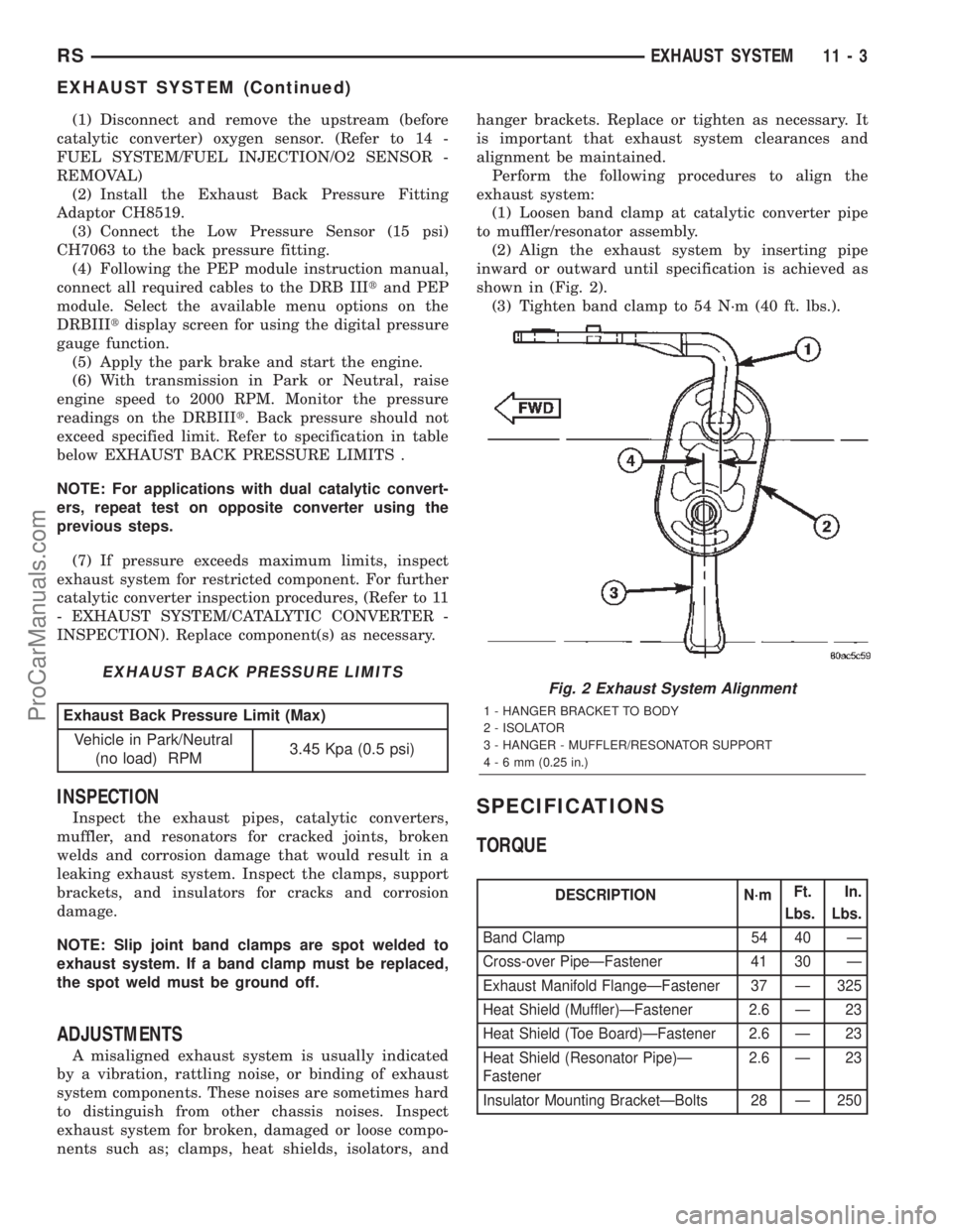
(2) Align the exhaust system by inserting pipe
inward or outward until specification is achieved as
shown in (Fig. 2).
(3) Tighten band clamp to 54 N´m (40 ft. lbs.).
SPECIFICATIONS
TORQUE
DESCRIPTION N´mFt.
Lbs.In.
Lbs.
Band Clamp 54 40 Ð
Cross-over PipeÐFastener 41 30 Ð
Exhaust Manifold FlangeÐFastener 37 Ð 325
Heat Shield (Muffler)ÐFastener 2.6 Ð 23
Heat Shield (Toe Board)ÐFastener 2.6 Ð 23
Heat Shield (Resonator Pipe)Ð
Fastener2.6 Ð 23
Insulator Mounting BracketÐBolts 28 Ð 250
Fig. 2 Exhaust System Alignment
1 - HANGER BRACKET TO BODY
2 - ISOLATOR
3 - HANGER - MUFFLER/RESONATOR SUPPORT
4-6mm(0.25 in.)
RSEXHAUST SYSTEM11-3
EXHAUST SYSTEM (Continued)
ProCarManuals.com
Page 1471 of 2399
Long Term
The second fuel correction program is the long
term adaptive memory. In order to maintain correct
emission throughout all operating ranges of the
engine, a cell structure based on engine rpm and load
(MAP) is used.
Ther number of cells varies upon the driving con-
ditions. Two cells are used only during idle, based
upon TPS and Park/Neutral switch inputs. There
may be two other cells used for deceleration, based
on TPS, engine rpm, and vehicle speed. The other
twelve cells represent a manifold pressure and an
rpm range. Six of the cells are high rpm and the
other six are low rpm. Each of these cells is a specific
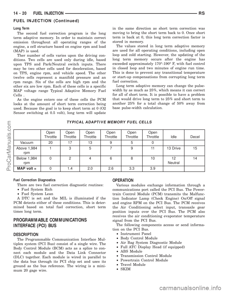
MAP voltage range Typical Adaptive Memory Fuel
Cells .
As the engine enters one of these cells the PCM
looks at the amount of short term correction being
used. Because the goal is to keep short term at 0 (O2
Sensor switching at 0.5 volt), long term will updatein the same direction as short term correction was
moving to bring the short term back to 0. Once short
term is back at 0, this long term correction factor is
stored in memory.
The values stored in long term adaptive memory
are used for all operating conditions, including open
loop and cold starting. However, the updating of the
long term memory occurs after the engine has
exceeded approximately 170É-190É F, with fuel control
in closed loop and two minutes of engine run time.
This is done to prevent any transitional temperature
or start-up compensations from corrupting long term
fuel correction.
Long term adaptive memory can change the pulse-
width by as much as 25%, which means it can correct
for all of short term. It is possible to have a problem
that would drive long term to 25% and short term to
another 25% for a total change of 50% away from
base pulse-width calculation.
TYPICAL ADAPTIVE MEMORY FUEL CELLS
Open
ThrottleOpen
ThrottleOpen
ThrottleOpen
ThrottleOpen
ThrottleOpen
Throttle Idle Decel
Vacuum 20 17 13 9 5 0
Above 1,984
rpm1 3 5 7 9 11 13 Drive 15
Below 1,984
rpm02 4 6 8 1012
Neutral14
MAP volt =0 1.4 2.0 2.6 3.3 3.9
Fuel Correction Diagnostics
There are two fuel correction diagnostic routines:
²Fuel System Rich
²Fuel System Lean
A DTC is set and the MIL is illuminated if the
PCM detects either of these conditions. This is deter-
mined based on total fuel correction, short term
times long term.
PROGRAMMABLE COMMUNICATIONS
INTERFACE (PCI) BUS
DESCRIPTION
The Programmable Communication Interface Mul-
tiplex system (PCI Bus) consist of a single wire. The
Body Control Module (BCM) acts as a splice to con-
nect each module and the Data Link Connector
(DLC) together. Each module is wired in parallel to
the data bus through its PCI chip set and uses its
ground as the bus reference. The wiring is a mini-
mum 20 gage wire.
OPERATION
Various modules exchange information through a
communications port called the PCI Bus. The Power-
train Control Module (PCM) transmits the Malfunc-
tion Indicator Lamp (Check Engine) On/Off signal
and engine RPM on the PCI Bus. The PCM receives
the Air Conditioning select input, transaxle gear
position inputs over the PCI Bus. The PCM also
receives the air conditioning evaporator temperature
signal from the PCI Bus.
The following components access or send informa-
tion on the PCI Bus.
²Instrument Panel
²Body Control Module
²Air Bag System Diagnostic Module
²Full ATC Display Head (if equipped)
²ABS Module
²Transmission Control Module
²Powertrain Control Module
²Travel Module
²SKIM
14 - 20 FUEL INJECTIONRS
FUEL INJECTION (Continued)
ProCarManuals.com
Page 1661 of 2399
ADJUSTMENTS
GEARSHIFT CABLE ADJUSTMENT
Lift and rotate the gearshift hand lever into the
park (P) gate position and remove the ignition key.
This confirms the shift lever is in the gated park (P)
position.
After confirming the park gate position, turn the
ignition switch . If the starter will operate, the park
gate position is correct. Move the shift lever into the
neutral (N) position. If the starter will operate in this
position, the linkage is properly adjusted. If the
starter fails to operate in either position, linkage
adjustment is required.
(1) Park the vehicle on level ground and set the
parking brake.
(2) Place the gearshift lever in park (P) gate posi-
tion and remove key.
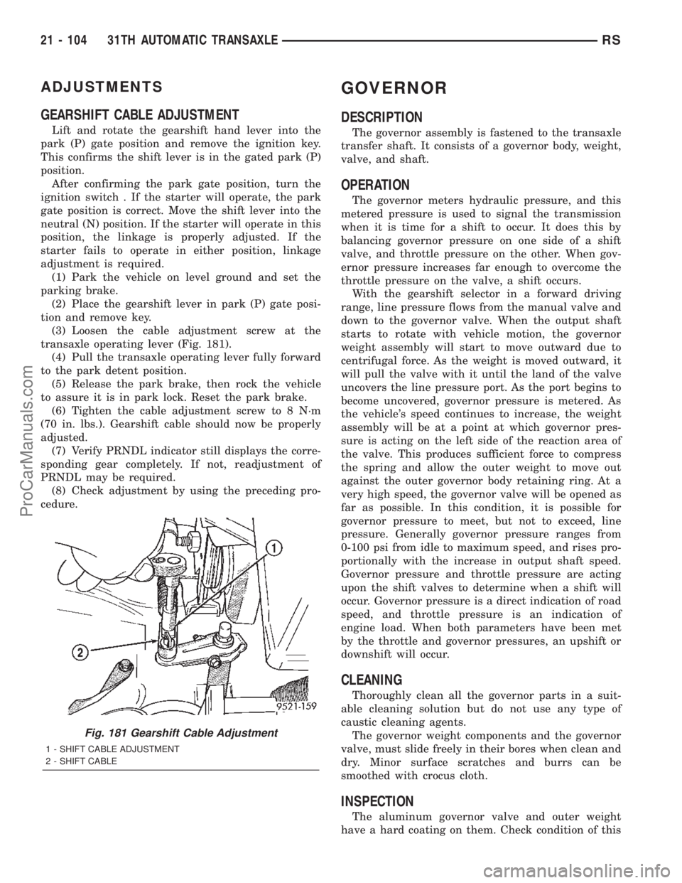
(3) Loosen the cable adjustment screw at the
transaxle operating lever (Fig. 181).
(4) Pull the transaxle operating lever fully forward
to the park detent position.
(5) Release the park brake, then rock the vehicle
to assure it is in park lock. Reset the park brake.
(6) Tighten the cable adjustment screw to 8 N´m
(70 in. lbs.). Gearshift cable should now be properly
adjusted.
(7) Verify PRNDL indicator still displays the corre-
sponding gear completely. If not, readjustment of
PRNDL may be required.
(8) Check adjustment by using the preceding pro-
cedure.
GOVERNOR
DESCRIPTION
The governor assembly is fastened to the transaxle
transfer shaft. It consists of a governor body, weight,
valve, and shaft.
OPERATION
The governor meters hydraulic pressure, and this
metered pressure is used to signal the transmission
when it is time for a shift to occur. It does this by
balancing governor pressure on one side of a shift
valve, and throttle pressure on the other. When gov-
ernor pressure increases far enough to overcome the
throttle pressure on the valve, a shift occurs.
With the gearshift selector in a forward driving
range, line pressure flows from the manual valve and
down to the governor valve. When the output shaft
starts to rotate with vehicle motion, the governor
weight assembly will start to move outward due to
centrifugal force. As the weight is moved outward, it
will pull the valve with it until the land of the valve
uncovers the line pressure port. As the port begins to
become uncovered, governor pressure is metered. As
the vehicle's speed continues to increase, the weight
assembly will be at a point at which governor pres-
sure is acting on the left side of the reaction area of
the valve. This produces sufficient force to compress
the spring and allow the outer weight to move out
against the outer governor body retaining ring. At a
very high speed, the governor valve will be opened as
far as possible. In this condition, it is possible for
governor pressure to meet, but not to exceed, line
pressure. Generally governor pressure ranges from
0-100 psi from idle to maximum speed, and rises pro-
portionally with the increase in output shaft speed.
Governor pressure and throttle pressure are acting
upon the shift valves to determine when a shift will
occur. Governor pressure is a direct indication of road
speed, and throttle pressure is an indication of
engine load. When both parameters have been met
by the throttle and governor pressures, an upshift or
downshift will occur.
CLEANING
Thoroughly clean all the governor parts in a suit-
able cleaning solution but do not use any type of
caustic cleaning agents.
The governor weight components and the governor
valve, must slide freely in their bores when clean and
dry. Minor surface scratches and burrs can be
smoothed with crocus cloth.
INSPECTION
The aluminum governor valve and outer weight
have a hard coating on them. Check condition of this
Fig. 181 Gearshift Cable Adjustment
1 - SHIFT CABLE ADJUSTMENT
2 - SHIFT CABLE
21 - 104 31TH AUTOMATIC TRANSAXLERS
ProCarManuals.com