remote control CHRYSLER VOYAGER 2002 Workshop Manual
[x] Cancel search | Manufacturer: CHRYSLER, Model Year: 2002, Model line: VOYAGER, Model: CHRYSLER VOYAGER 2002Pages: 2399, PDF Size: 57.96 MB
Page 1527 of 2399

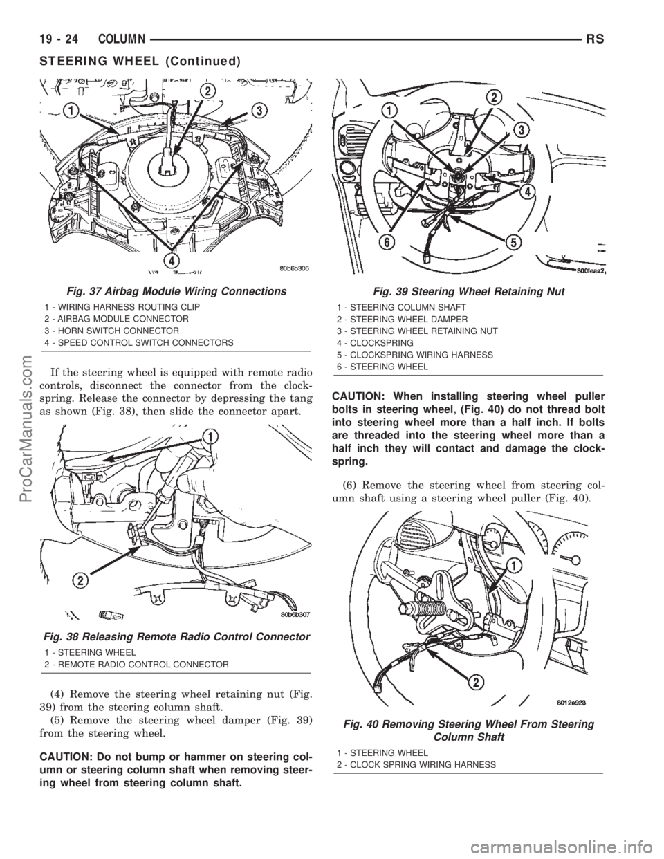
If the steering wheel is equipped with remote radio
controls, disconnect the connector from the clock-
spring. Release the connector by depressing the tang
as shown (Fig. 38), then slide the connector apart.
(4) Remove the steering wheel retaining nut (Fig.
39) from the steering column shaft.
(5) Remove the steering wheel damper (Fig. 39)
from the steering wheel.
CAUTION: Do not bump or hammer on steering col-
umn or steering column shaft when removing steer-
ing wheel from steering column shaft.CAUTION: When installing steering wheel puller
bolts in steering wheel, (Fig. 40) do not thread bolt
into steering wheel more than a half inch. If bolts
are threaded into the steering wheel more than a
half inch they will contact and damage the clock-
spring.
(6) Remove the steering wheel from steering col-
umn shaft using a steering wheel puller (Fig. 40).
Fig. 37 Airbag Module Wiring Connections
1 - WIRING HARNESS ROUTING CLIP
2 - AIRBAG MODULE CONNECTOR
3 - HORN SWITCH CONNECTOR
4 - SPEED CONTROL SWITCH CONNECTORS
Fig. 38 Releasing Remote Radio Control Connector
1 - STEERING WHEEL
2 - REMOTE RADIO CONTROL CONNECTOR
Fig. 39 Steering Wheel Retaining Nut
1 - STEERING COLUMN SHAFT
2 - STEERING WHEEL DAMPER
3 - STEERING WHEEL RETAINING NUT
4 - CLOCKSPRING
5 - CLOCKSPRING WIRING HARNESS
6 - STEERING WHEEL
Fig. 40 Removing Steering Wheel From Steering
Column Shaft
1 - STEERING WHEEL
2 - CLOCK SPRING WIRING HARNESS
19 - 24 COLUMNRS
STEERING WHEEL (Continued)
ProCarManuals.com
Page 1528 of 2399

INSTALLATION
CAUTION: Do not force steering wheel onto steer-
ing column shaft by driving it on. Pull steering
wheel down onto shaft using only the steering
wheel retaining nut.
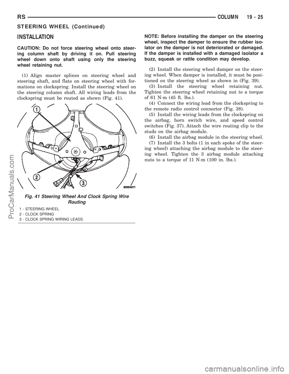
(1) Align master splines on steering wheel and
steering shaft, and flats on steering wheel with for-
mations on clockspring. Install the steering wheel on
the steering column shaft. All wiring leads from the
clockspring must be routed as shown (Fig. 41).NOTE: Before installing the damper on the steering
wheel, inspect the damper to ensure the rubber iso-
lator on the damper is not deteriorated or damaged.
If the damper is installed with a damaged isolator a
buzz, squeak or rattle condition may develop.
(2) Install the steering wheel damper on the steer-
ing wheel. When damper is installed, it must be posi-
tioned on the steering wheel as shown in (Fig. 39).
(3) Install the steering wheel retaining nut.
Tighten the steering wheel retaining nut to a torque
of 61 N´m (45 ft. lbs.).
(4) Connect the wiring lead from the clockspring to
the remote radio control connector (Fig. 38).
(5) Install the wiring leads from the clockspring on
the airbag, horn switch wire, and speed control
switches (Fig. 37). Attach the wire routing clip to the
studs on the airbag module.
(6) Install the airbag module in the steering wheel.
(7) Install the 3 bolts (1 in each spoke of the steer-
ing wheel) attaching the airbag module to the steer-
ing wheel. Tighten the 3 airbag module attaching
nuts to a torque of 11 N´m (100 in. lbs.).
Fig. 41 Steering Wheel And Clock Spring Wire
Routing
1 - STEERING WHEEL
2 - CLOCK SPRING
3 - CLOCK SPRING WIRING LEADS
RSCOLUMN19-25
STEERING WHEEL (Continued)
ProCarManuals.com
Page 1579 of 2399

ASSEMBLY...........................115
SHIFT INTERLOCK SOLENOID
DESCRIPTION........................115
OPERATION..........................115
DIAGNOSIS AND TESTING - BRAKE/
TRANSMISSION SHIFT INTERLOCK
SOLENOID..........................117
REMOVAL............................117
INSTALLATION........................118
SOLENOID - TCC
DESCRIPTION........................119
OPERATION..........................119
REMOVAL............................119
INSTALLATION........................120
THROTTLE VALVE CABLE
REMOVAL............................120
INSTALLATION........................121
ADJUSTMENTS
THROTTLE VALVE LINKAGE
ADJUSTMENT.......................122
TORQUE CONVERTER
DESCRIPTION........................122
OPERATION..........................126
REMOVAL............................127
INSTALLATION........................127
TRANSFER SYSTEM - OUTPUT SHAFT/GEAR/
BEARING
REMOVAL............................128INSTALLATION........................131
ADJUSTMENTS
ADJUSTMENT - OUTPUT SHAFT BEARING . 135
TRANSFER SYSTEM - TRANSFER SHAFT/
GEAR/BEARING
REMOVAL............................137
INSTALLATION........................141
ADJUSTMENTS
ADJUSTMENT - TRANSFER SHAFT
BEARING...........................145
VALVE BODY
REMOVAL............................146
DISASSEMBLY........................148
CLEANING...........................154
INSPECTION.........................155
ASSEMBLY...........................155
INSTALLATION........................158
ADJUSTMENTS
HYDRAULIC CONTROL PRESSURE
ADJUSTMENTS......................160
VEHICLE SPEED SENSOR/PINION GEAR
REMOVAL............................160
INSTALLATION........................160
31TH AUTOMATIC
TRANSAXLE
DESCRIPTION
This transaxle combines torque converter, three
speed transmission, final drive gearing, and differen-
tial into a front wheel drive system.
Within this transaxle, there are three primary
areas:
(1) Main center line plus valve body.
(2) Transfer shaft center line (includes governor
and parking sprag).
(3) Differential center line.
Center distances between the main rotating parts
in these three areas are held precise to maintain a
low noise level.
The torque converter, transaxle area, and differen-
tial are housed in an integral aluminum die casting.
The differential oil sump is common with the
transaxle sump. Separate filling of the differen-
tial is NOT necessary.
The torque converter is attached to the crankshaft
through a flexible driving plate. Cooling of the con-
verter is accomplished by circulating the transaxle
fluid through a remote cooler. There are two types of
coolers used. An oil-to-water type cooler located in
the radiator side tank and/or an oil-to-air heatexchanger. The torque converter assembly is a sealed
unit that cannot be disassembled.
The transaxle fluid is filtered by an internal filter
attached to the lower side of the valve body assembly.
Engine torque is transmitted to the torque con-
verter and then through the input shaft to multiple-
disc clutches in the transaxle. The power flow
depends on the application of the clutches and bands.
Refer to Elements in Use Chart in Diagnosis and
Tests section.
The transaxle consists of:
²Two multiple-disc clutches
²An overrunning clutch
²Two servos
²A hydraulic accumulator
²Two bands
²Two planetary gear sets
This provides three forward ratios and a reverse
ratio. The common sun gear of the planetary gear
sets is connected to the front clutch by a driving
shell. The driving shell is splined to the sun gear and
front clutch retainer. The hydraulic system consists
of an oil pump and a single valve body which con-
tains all of the valves except the governor valves.
The transaxle sump and differential sump are both
vented through the dipstick. Output torque from the
main center line is delivered through helical gears to
the transfer shaft. This gear set is a factor in the
transaxle final drive (axle) ratio. The shaft also car-
21 - 22 31TH AUTOMATIC TRANSAXLERS
ProCarManuals.com
Page 1996 of 2399

MOPARTSPRAY WHITE LUBE OR EQUIVALENT
²Door Check Straps
²Liftgate Latches
²Liftgate Prop Pivots
²Ash Receiver
²Fuel Filler Door Remote Control Latch Mecha-
nism
²Parking Brake Mechanism
²Sliding Seat Tracks
²Liftgate Latch
MOPARTMultipurpose GREASE OR EQUIVALENT
²All Other Hood Mechanisms
MOPARTLOCK CYLINDER LUBRICANT OR
EQUIVALENT
²Door Lock Cylinders
²Liftgate Lock Cylinder
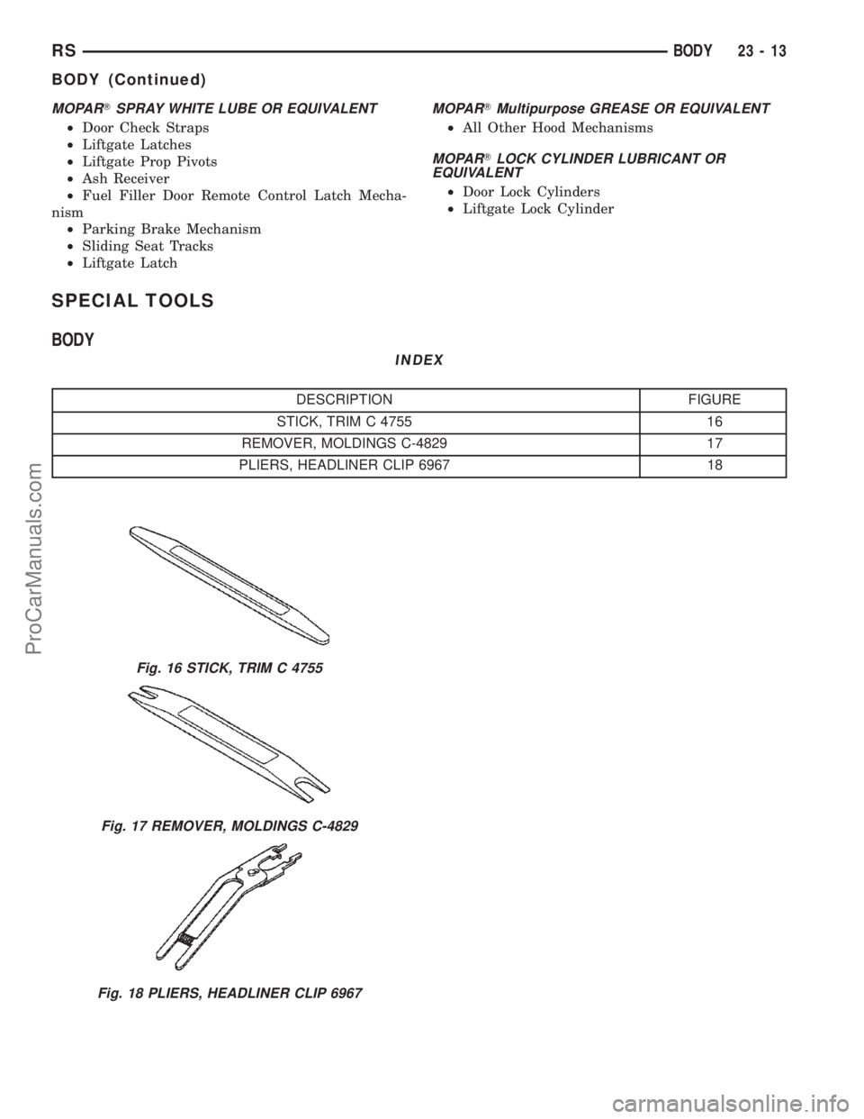
SPECIAL TOOLS
BODY
INDEX
DESCRIPTION FIGURE
STICK, TRIM C 4755 16
REMOVER, MOLDINGS C-4829 17
PLIERS, HEADLINER CLIP 6967 18
Fig. 16 STICK, TRIM C 4755
Fig. 17 REMOVER, MOLDINGS C-4829
Fig. 18 PLIERS, HEADLINER CLIP 6967
RSBODY23-13
BODY (Continued)
ProCarManuals.com
Page 2284 of 2399

or damaged, the instrument panel top cover must be
replaced.
²Demister Outlets- There are two side window
demisters that aid in defogging and defrosting the
front door windows. One demister outlet is located at
each outboard end of the instrument panel top pad,
near the belt line at the A-pillars. The demister out-
lets can be removed from the top pad individually for
service replacement.
²Instrument Panel Outlets- There are five
panel outlets in the instrument panel, one located
near each outboard end of the instrument panel fac-
ing the rear of the vehicle, and three located near the
top of the instrument panel center bezel. On models
with manual temperature control, all five of these
outlets are fully adjustable. On models with Auto-
matic Temperature Control (ATC), the center outlet
in the center bezel has fixed vanes because it also
houses the remote infrared temperature sensors for
the front seat positions. The outboard outlets can be
removed individually for service replacement. The
center bezel outlets are serviced as a gang of three
outlets and, on models with ATC, also includes the
infrared sensors.
²Front Door Rear Outlets- A fully adjustable
outlet located at the rear of each front door trim
panel supplies only cooled air to the intermediate
seat passengers. Air is supplied to these outlets from
the instrument panel through ducts in the doors that
use molded seals at the instrument panel to prevent
air leakage. The door ducts are integral to the front
door trim panels. These outlets also incorporate a red
reflector to improve the safety and visibility of an
opened front door to traffic approaching the vehicle
from the rear at night. These outlets can be removed
from the door trim panels for service replacement.
²Front Floor Outlets- There are two front floor
outlets, one located above each side of the floor panel
center tunnel below the instrument panel. These out-
lets are integral to the front heater-A/C unit distri-
bution housing.
²Rear Floor Outlets- Wide rear floor outlets
located under each front seat have integral, fixed
directional dividers to distribute heated air across
the floor for intermediate seat passengers. These out-
lets are integral to the floor distribution ducts routed
under the front floor carpet from an outlet nozzle on
the bottom of the front heater-A/C unit distribution
housing.
REMOVAL
REMOVAL - CENTER BEZEL OUTLETS
The three outlets located near the top of the
instrument panel center bezel are serviced only as a
set of all three outlets. If the vehicle is equipped withthe optional Automatic Temperature Control (ATC)
system, the center outlet of the three has fixed vanes
and also houses the remote front infrared tempera-
ture sensors.
WARNING: ON VEHICLES EQUIPPED WITH AIR-
BAGS, DISABLE THE AIRBAG SYSTEM BEFORE
ATTEMPTING ANY STEERING WHEEL, STEERING
COLUMN, OR INSTRUMENT PANEL COMPONENT
DIAGNOSIS OR SERVICE. DISCONNECT AND ISO-
LATE THE BATTERY NEGATIVE (GROUND) CABLE,
THEN WAIT TWO MINUTES FOR THE AIRBAG SYS-
TEM CAPACITOR TO DISCHARGE BEFORE PER-
FORMING FURTHER DIAGNOSIS OR SERVICE. THIS
IS THE ONLY SURE WAY TO DISABLE THE AIRBAG
SYSTEM. FAILURE TO TAKE THE PROPER PRE-
CAUTIONS COULD RESULT IN ACCIDENTAL AIR-
BAG DEPLOYMENT AND POSSIBLE PERSONAL
INJURY.
(1) Disconnect and isolate the battery negative
cable.
(2) Remove the center bezel from the instrument
panel. (Refer to 23 - BODY/INSTRUMENT PANEL/
INSTRUMENT PANEL CENTER BEZEL - REMOV-
AL).
(3) Place the center bezel face down on a suitable
work surface. Be certain to take the proper precau-
tions to protect the face of the center bezel from cos-
metic damage.
(4) If the vehicle is equipped with the optional
ATC system, disconnect the ATC remote infrared
temperature sensor jumper harness from the sensor
connector receptacle located on the bottom of the cen-
ter outlet housing (Fig. 3).
(5) Remove the three screws that secure the bot-
tom of the outlet housing to the center bezel.
(6) Roll the bottom of the outlet housing upwards
towards the top of the center bezel far enough to dis-
engage the retainer features on the top of the outlet
housing from their receptacles at the top of the cen-
ter bezel.
(7) Remove the center bezel outlets and housing
from the center bezel as a unit.
REMOVAL - DEMISTER OUTLET
(1) Using a trim stick or another suitable wide
flat-bladed tool, gently pry the outer perimeter of the
demister outlet away from the instrument panel top
pad until the snap features on the outlet are released
(Fig. 4).
(2) Remove the demister outlet from the demister
duct opening in the instrument panel top pad.
REMOVAL - FRONT DOOR REAR OUTLET
(1) Disconnect and isolate the battery negative
cable.
RSDISTRIBUTION - FRONT24-41
AIR OUTLETS (Continued)
ProCarManuals.com
Page 2286 of 2399

INSTALLATION
INSTALLATION - CENTER BEZEL OUTLETS
(1) Position the center bezel outlets and housing
onto the center bezel as a unit.
(2) Engage the retainer features on the top of the
outlet housing with their receptacles at the top of the
center bezel, then roll the bottom of the outlet hous-
ing downwards towards the center bezel.
(3) Install and tighten the three screws that secure
the bottom of the outlet housing to the center bezel.
Tighten the screws to 2 N´m (17 in. lbs.).
(4) If the vehicle is equipped with the optional
ATC system, reconnect the ATC remote infrared tem-
perature sensor jumper harness to the sensor connec-
tor receptacle located on the bottom of the center
outlet housing.
(5) Reinstall the center bezel onto the instrument
panel. (Refer to 23 - BODY/INSTRUMENT PANEL/
INSTRUMENT PANEL CENTER BEZEL - INSTAL-
LATION).
(6) Reconnect the battery negative cable.
INSTALLATION - DEMISTER OUTLET
(1) Position the demister outlet over the demister
duct opening in the instrument panel top pad.
(2) Using hand pressure, press the demister outlet
firmly and evenly into the instrument panel top pad
opening until the snap features on the outlet are
fully engaged.
INSTALLATION - FRONT DOOR REAR OUTLET
(1) Position the front door rear outlet through the
outside of the front door trim panel outlet opening.
(2) While keeping the outlet aligned with the door
duct opening behind the trim panel, use hand pres-
sure to press the outlet firmly and evenly through
the outside of the front door trim panel outlet open-
ing until the four latch features (two top and two bot-
tom) that secure the outlet to the inside of the
opening are fully engaged.
(3) Reinstall the trim panel onto the front door
inner panel. (Refer to 23 - BODY/DOOR - FRONT/
TRIM PANEL - INSTALLATION).
(4) Reconnect the battery negative cable.
INSTALLATION - INSTRUMENT PANEL OUTLET
(1) Position the instrument panel outlet into the
panel duct opening in the instrument panel top pad.
(2) Using hand pressure, press the instrument
panel outlet firmly and evenly into the instrument
panel top pad opening until the snap features on the
outlet are fully engaged.
BLOWER MOTOR
DESCRIPTION
The blower motor is a 12-volt, Direct Current (DC)
motor with a squirrel cage-type blower wheel that is
secured to the blower motor shaft (Fig. 7). The
blower motor and wheel are located near the passen-
ger side end of the heater-A/C unit within the two
halves of the intake air housing in the passenger
compartment below the instrument panel. The
blower motor and blower motor wheel are a factory
balanced unit and cannot be adjusted or repaired. If
faulty or damaged, the blower motor and blower
wheel must be replaced as a unit.
OPERATION
The blower motor will operate whenever the igni-
tion switch is in the On position and the heater-A/C
control power is turned on. The blower motor can
only be turned off by turning off the power at the
heater-A/C control. The blower motor receives battery
current whenever the front blower motor relay is
energized. The front blower motor relay output cir-
cuit is protected by a fuse in the Intelligent Power
Module (IPM) located in the engine compartment
near the battery. In the Manual system, the blower
motor speed is controlled by regulating the path to
ground through the blower control switch and the
blower motor resistor. In the ATC system, the blower
motor speed is controlled by an electronic blower
power module, which uses a pulse width modulated
input from the ATC module and feedback from the
blower motor to regulate the blower motor ground
Fig. 7 Blower Motor
1 - BLOWER MOTOR
2 - RUBBER GROMMET
3 - BLOWER MOTOR CONNECTOR
4 - MOUNTING TABS
RSDISTRIBUTION - FRONT24-43
AIR OUTLETS (Continued)
ProCarManuals.com