fuel cap release CHRYSLER VOYAGER 2002 Service Manual
[x] Cancel search | Manufacturer: CHRYSLER, Model Year: 2002, Model line: VOYAGER, Model: CHRYSLER VOYAGER 2002Pages: 2399, PDF Size: 57.96 MB
Page 561 of 2399
read and diagnose these trouble codes. Refer to the
Body Diagnostic Manual for a complete list of diag-
nostic routines.
NOTE: It may be possible to generate Sliding Door
Diagnostic Trouble Codes during normal power
sliding door operation. Refer to the Body Diagnos-
tic Manual for a complete list of diagnostic routines.
For additional information, (Refer to 8 - ELECTRI-
CAL/POWER DOORS - OPERATION). For a com-
plete power sliding door system wiring schematic,
refer to Wiring Diagrams. For power sliding door sys-
tem operation instructions, refer to the vehicle owner
manual.
WARNING: BE CERTAIN TO READ ALL WARNINGS
AND CAUTIONS IN POWER SLIDING DOOR OPER-
ATION BEFORE ATTEMPTING ANY SERVICE OF
POWER SLIDING DOOR SYSTEM OR COMPO-
NENTS.
OPERATION
With the push of a power sliding door open/close
command switch (key fob, overhead console or B-pil-
lar mounted) a signal is sent out to the Body Control
Module (BCM). The BCM then sends a signal out on
the PCI Data Bus circuit (J1850) to the power sliding
door module. The power sliding door module then
signals the power sliding door latch to release the
door to the unlatched and movable position. The
motor then starts an open cycle.During the door open cycle, if the power sliding
door module detects sufficient resistance to door
travel, such as an obstruction in the door's path, the
power sliding door module will immediately stop door
movement and reverse door travel to the full open or
closed position. The ability for the power sliding door
module to detect resistance to door travel is accom-
plished by hall effect sensors and the door motor
speed.
The power sliding door control module has the abil-
ity to learn. Anytime a door is opened or closed using
the power sliding door system the module learns
from its cycle. If a replacement power sliding door
component is installed or a door adjustment is made,
the module must re-learn the effort required to open
or close the door. A learn cycle can be performed with
a Diagnostic Scan Tool, such as the DRB IIIt, or with
a complete cycle of the door, using any one of the
command switches. Refer to Standard Procedures in
this section for detailed instructions.
The power sliding door system is designed with a
number of system inhibitors. These inhibitors are
necessary for safety and/or feasibility of the power
sliding door system. See the power sliding door sys-
tem inhibitors noted below:
POWER SLIDING DOOR SYSTEM INHIBITORS
²The power sliding door must be in thefullopen
or closed position in order for the power sliding door
system to start a cycle. If the door is not in this posi-
tion (based on the input from the full open, pawl or
ratchet switches) the door control module will not
respond to command switch inputs.
²The vehicles transmission must be inpark or
neutralin order for the power sliding door system to
start a cycle.
²The vehicles child lockout switch must be in the
ªUNLOCKEDº position in order for the power sliding
door systems B-pillar switches to function.
²If multiple obstacles are detected during the
same power open or close cycle the power sliding
door may go into full manual mode.
²If severe Diagnostic Trouble Codes (DTC) are
stored in the power sliding door control module the
power sliding door may go into full manual mode.
²Due to the high pressure created in the passen-
ger compartment with the blower motor on high, the
power sliding door may not complete a power close
cycle unless a window is cracked, allowing the pres-
sure to escape. This situation will only be experi-
enced on some vehicles, or vehicles with brand new
side door weather seals installed. Refer to the Side
Door Adjustment procedure in the Standard Proce-
dures section of this group.
²The vehicles fuel tank filler door must be in the
closed position. Due to the sliding door interference
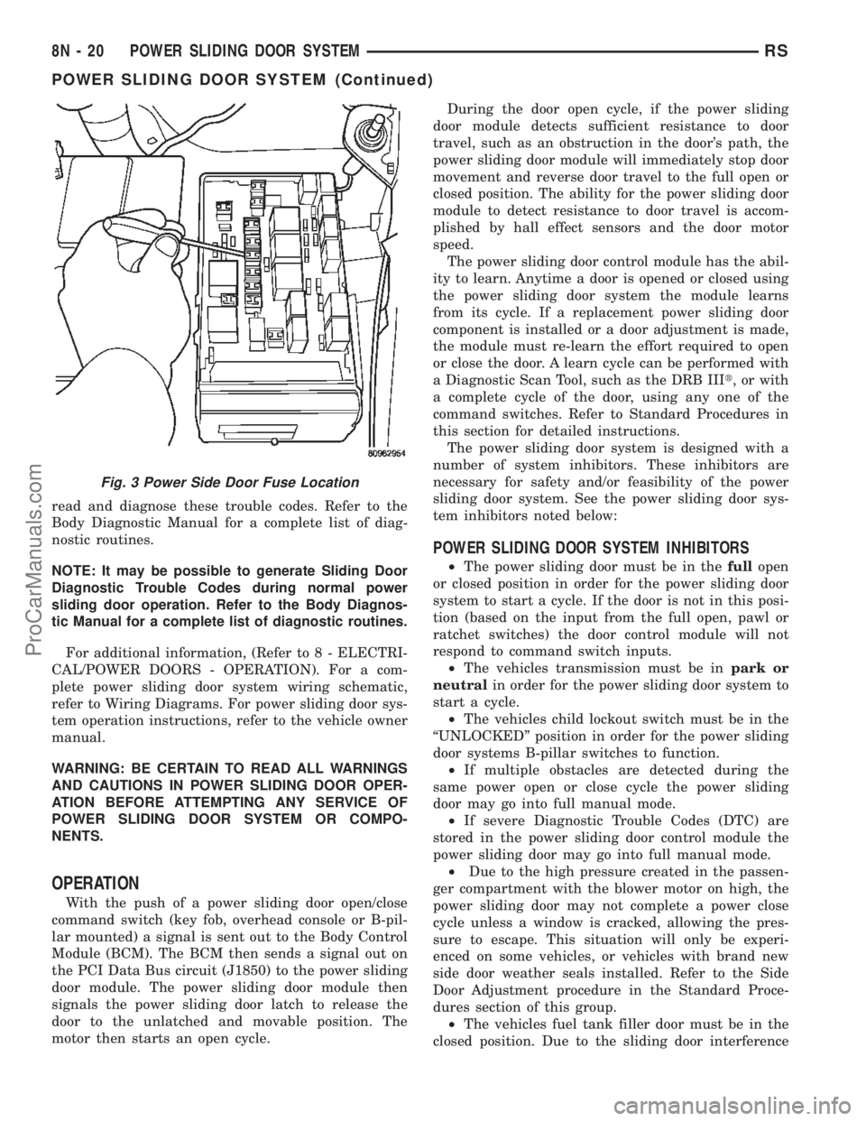
Fig. 3 Power Side Door Fuse Location
8N - 20 POWER SLIDING DOOR SYSTEMRS
POWER SLIDING DOOR SYSTEM (Continued)
ProCarManuals.com
Page 1213 of 2399

NOTE: Multi-Layer Steel (MLS) head gaskets require
a scratch free sealing surface.
Only use the following for cleaning gasket surfaces:
²Solvent or a commercially available gasket
remover
²Plastic or wood scraper (Fig. 3)
²Drill motor with 3M RolocŸ Bristle Disc (white
or yellow) (Fig. 3)
CAUTION: Excessive pressure or high RPM (beyond
the recommended speed), can damage the sealing
surfaces. The mild (white, 120 grit) bristle disc is
recommended. If necessary, the medium (yellow, 80
grit) bristle disc may be used on cast iron surfaces
with care.
STANDARD PROCEDURE - MEASURING
BEARING CLEARANCE USING PLASTIGAGE
Engine crankshaft bearing clearances can be deter-
mined by use of Plastigage or equivalent. The follow-
ing is the recommended procedure for the use of
Plastigage:
(1) Remove oil film from surface to be checked.
Plastigage is soluble in oil.
(2) Place a piece of Plastigage across the entire
width of the bearing shell in the cap approximately
6.35 mm (1/4 in.) off center and away from the oil
holes (Fig. 4). (In addition, suspected areas can be
checked by placing the Plastigage in the suspected
area). Torque the bearing cap bolts of the bearing
being checked to the proper specifications.(3) Remove the bearing cap and compare the
width of the flattened Plastigage with the metric
scale provided on the package. Locate the band clos-
est to the same width. This band shows the amount
of clearance in thousandths of a millimeter. Differ-
ences in readings between the ends indicate the
amount of taper present. Record all readings taken.
Compare clearance measurements to specs found in
engine specifications (Refer to 9 - ENGINE - SPECI-
FICATIONS).Plastigage generally is accompa-
nied by two scales. One scale is in inches, the
other is a metric scale.
NOTE: Plastigage is available in a variety of clear-
ance ranges. Use the most appropriate range for
the specifications you are checking.
(4) Install the proper crankshaft bearings to
achieve the specified bearing clearances.
REMOVAL - ENGINE ASSEMBLY
(1) Perform fuel pressure release procedure (Refer
to 14 - FUEL SYSTEM/FUEL DELIVERY - STAN-
DARD PROCEDURE)
(2) Disconnect battery negative cable.
(3) Remove air cleaner housing and inlet tube.
(4) Disconnect the fuel line from fuel rail. (Refer to
14 - FUEL SYSTEM/FUEL DELIVERY/FUEL LINES
- STANDARD PROCEDURE)
(5) Disconnect all vacuum hoses.
(6) Drain cooling system. (Refer to 7 - COOLING -
STANDARD PROCEDURE)
(7) Remove radiator fans. (Refer to 7 - COOLING/
ENGINE/RADIATOR FAN - REMOVAL)
(8) Remove radiator upper and lower hoses.
Fig. 3 Proper Tool Usage For Surface Preparation
1 - ABRASIVE PAD
2 - 3M ROLOCŸ BRISTLE DISC
3 - PLASTIC/WOOD SCRAPER
Fig. 4 Plastigage Placed in Lower ShellÐTypical
1 - PLASTIGAGE
9 - 12 ENGINE 2.4LRS
ENGINE 2.4L (Continued)
ProCarManuals.com
Page 1226 of 2399
Possible indications of the cylinder head gasket
leaking between adjacent cylinders are:
²Loss of engine power
²Engine misfiring
²Poor fuel economy
Possible indications of the cylinder head gasket
leaking between a cylinder and an adjacent water
jacket are:
²Engine overheating
²Loss of coolant
²Excessive steam (white smoke) emitting from
exhaust
²Coolant foaming
CYLINDER-TO-CYLINDER LEAKAGE TEST
To determine if an engine cylinder head gasket is
leaking between adjacent cylinders, follow the proce-
dures in Cylinder Compression Pressure Test (Refer
to 9 - ENGINE - DIAGNOSIS AND TESTING). An
engine cylinder head gasket leaking between adja-
cent cylinders will result in approximately a 50±70%
reduction in compression pressure.
CYLINDER-TO-WATER JACKET LEAKAGE TEST
WARNING: USE EXTREME CAUTION WHEN THE
ENGINE IS OPERATING WITH COOLANT PRES-
SURE CAP REMOVED.VISUAL TEST METHOD
With the engine cool, remove the coolant pressure
cap. Start the engine and allow it to warm up until
thermostat opens.
If a large combustion/compression pressure leak
exists, bubbles will be visible in the coolant.
COOLING SYSTEM TESTER METHOD
WARNING: WITH COOLING SYSTEM TESTER IN
PLACE, PRESSURE WILL BUILD UP FAST. EXCES-
SIVE PRESSURE BUILT UP, BY CONTINUOUS
ENGINE OPERATION, MUST BE RELEASED TO A
SAFE PRESSURE POINT. NEVER PERMIT PRES-
SURE TO EXCEED 138 kPa (20 psi).
Install Cooling System Tester 7700 or equivalent to
pressure cap neck. Start the engine and observe the
tester's pressure gauge. If gauge pulsates with every
power stroke of a cylinder a combustion pressure
leak is evident.
CHEMICAL TEST METHOD
Combustion leaks into the cooling system can also
be checked by using Bloc-Chek Kit C-3685-A or
equivalent. Perform test following the procedures
supplied with the tool kit.
REMOVAL - CYLINDER HEAD
(1) Perform fuel system pressure release procedure
before attempting any repairs.(Refer to 14 -
FUEL SYSTEM/FUEL DELIVERY - SPECIFICA-
TIONS)
(2) Disconnect battery negative cable.
(3) Drain cooling system. (Refer to 7 - COOLING -
STANDARD PROCEDURE)
(4) Remove air filter housing and inlet tube.
(5) Remove upper intake manifold. (Refer to 9 -
ENGINE/MANIFOLDS/INTAKE MANIFOLD -
REMOVAL)
(6) Remove heater tube support bracket from cyl-
inder head.
(7) Disconnect radiator upper and heater supply
hoses from intake manifold water outlet connections.
(8) Remove accessory drive belts. (Refer to 7 -
COOLING/ACCESSORY DRIVE/DRIVE BELTS -
REMOVAL)
(9) Raise vehicle and remove exhaust pipe from
manifold.
(10) Remove power steering pump reservoir and
line support bracket from lower intake manifold and
set aside. Do not disconnect lines.
(11) Remove ignition coil and wires from engine.
(12) Disconnect cam sensor and fuel injector wir-
ing connectors.
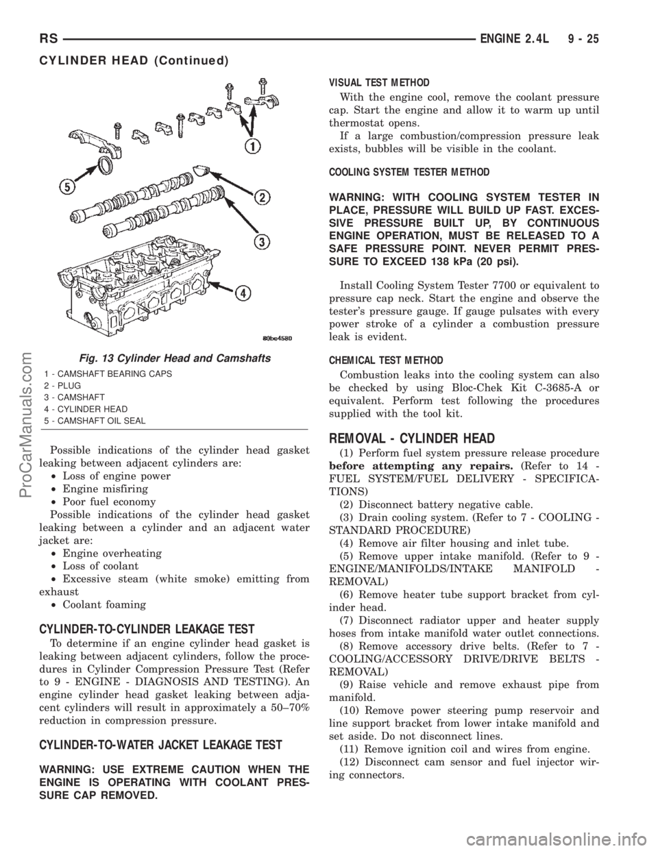
Fig. 13 Cylinder Head and Camshafts
1 - CAMSHAFT BEARING CAPS
2 - PLUG
3 - CAMSHAFT
4 - CYLINDER HEAD
5 - CAMSHAFT OIL SEAL
RSENGINE 2.4L9-25
CYLINDER HEAD (Continued)
ProCarManuals.com
Page 1301 of 2399
INSTALLATION
(1) Install air box into vehicle and onto the locat-
ing pin.
(2) Install bolt to hold air box to the upper radia-
tor cross member.
(3) Install the inlet hose to the throttle body.
(4) Connect the inlet air temperature sensor (Fig.
16).
(5) Connect the negative battery cable.
CYLINDER HEAD
DESCRIPTION
The aluminum cylinder heads (Fig. 17) are
designed to create high flow combustion chambers to
improve performance, while minimizing the change
to the burn rate in the chamber. The cylinder head
incorporates the combustion chamber. Two valves
per-cylinder are used with inserted valve seats and
guides. A multi-layer steel (MLS) type gasket is used
between the cylinder head and engine block.
OPERATION
The cylinder head closes the combustion chamber,
allowing the pistons to compress the fuel/air mixture
for ignition. The valves are actuated by the lobe pro-
files on the camshaft to open and close at specified
duration to either allow clean air in the combustion
chamber or the exhaust gases out; depending on the
stroke of the engine.
DIAGNOSIS AND TESTINGÐCYLINDER HEAD
GASKET
A cylinder head gasket leak can be located between
adjacent cylinders or between a cylinder and the
adjacent water jacket.
Possible indications of the cylinder head gasket
leaking between adjacent cylinders are:
²Loss of engine power
²Engine misfiring
²Poor fuel economy
Possible indications of the cylinder head gasket
leaking between a cylinder and an adjacent water
jacket are:
²Engine overheating
²Loss of coolant
²Excessive steam (white smoke) emitting from
exhaust
²Coolant foaming
CYLINDER-TO-CYLINDER LEAKAGE TEST
To determine if an engine cylinder head gasket is
leaking between adjacent cylinders, follow the proce-
dures in Cylinder Compression Pressure Test (Refer
to 9 - ENGINE - DIAGNOSIS AND TESTING). An
engine cylinder head gasket leaking between adja-
cent cylinders will result in approximately a 50±70%
reduction in compression pressure.
CYLINDER-TO-WATER JACKET LEAKAGE TEST
WARNING: USE EXTREME CAUTION WHEN THE
ENGINE IS OPERATING WITH COOLANT PRES-
SURE CAP REMOVED.
VISUAL TEST METHOD
With the engine cool, remove the coolant pressure
cap. Start the engine and allow it to warm up until
thermostat opens.
If a large combustion/compression pressure leak
exists, bubbles will be visible in the coolant.
COOLING SYSTEM TESTER METHOD
WARNING: WITH COOLING SYSTEM TESTER IN
PLACE, PRESSURE WILL BUILD UP FAST. EXCES-
SIVE PRESSURE BUILT UP, BY CONTINUOUS
ENGINE OPERATION, MUST BE RELEASED TO A
SAFE PRESSURE POINT. NEVER PERMIT PRES-
SURE TO EXCEED 138 kPa (20 psi).
Install Cooling System Tester 7700 or equivalent to
pressure cap neck. Start the engine and observe the
tester's pressure gauge. If gauge pulsates with every
power stroke of a cylinder a combustion pressure
leak is evident.
CHEMICAL TEST METHOD
Combustion leaks into the cooling system can also
be checked by using Bloc-Chek Kit C-3685-A or
equivalent. Perform test following the procedures
supplied with the tool kit.
REMOVAL - CYLINDER HEAD
(1) Drain the cooling system. (Refer to 7 - COOL-
ING - STANDARD PROCEDURE)
(2) Disconnect negative cable from battery.
(3) Remove upper and lower intake manifolds.
(Refer to 9 - ENGINE/MANIFOLDS/INTAKE MANI-
FOLD - REMOVAL)
WARNING: INTAKE MANIFOLD GASKET IS MADE
OF VERY THIN METAL AND MAY CAUSE PER-
SONAL INJURY, HANDLE WITH CARE.
9 - 100 ENGINE 3.3/3.8LRS
AIR CLEANER HOUSING (Continued)
ProCarManuals.com
Page 1455 of 2399

FUEL FILTER
REMOVAL
(1) Release fuel pressure, refer to the Fuel release
procedure in this section.
(2) Disconnect the negative battery cable.
(3) Raise vehicle and support.
(4) Support the fuel tank with a transmission jack.
(5) Remove fuel line from the front of the tank.
(6) Remove ground strap
(7) Remove the inboard side of the fuel tank straps
and front T strap fastner.
(8) Lower the tank about 6 inches (Fig. 1).
(9) Remove fuel lines from the fuel pump module.
(10) Remove fuel filter from tank.
INSTALLATION
(1) Install fuel filter to tank. Tighten bolt to 4.5
N´m (40 in. lbs.)
(2) Install fuel lines to the fuel pump module (Fig.
1).
(3) Raise tank into position.
(4) Install the fuel tank straps.Tighten bolt for
main straps to 54 N´m (40 ft. lbs.) and the T strap
bolt to 28.2 N´m (250 in. lbs.)
(5) Install the ground strap
(6) Connect the fuel line at the front of the tank.
(7) Lower vehicle.
(8) Connect the negative battery cable.
(9) Pressurize the fuel system with the DRBIIIt
and check for leaks.
FUEL LEVEL SENDING UNIT /
SENSOR
DESCRIPTION
The fuel gauge level sending unit is attached to the
side of fuel pump module. The level sensor is a vari-
able resistor.
OPERATION
Its resistance changes with the amount of fuel in
the tank. The float arm attached to the sensor moves
as the fuel level changes.
The fuel level input is used as an input for OBD II.
If the fuel level is below 15% or above 85% of total
tank capacity several monitors are disabled. There
are diagnostics for the level circuit open and shorted.
REMOVAL
Remove fuel pump module. Refer to Fuel Pump
Module in this section.
(1) Depress retaining tab and remove the fuel
pump/level sensor connector from theBOTTOMof
the fuel pump module electrical connector (Fig. 2) .
NOTE: The pump module harness on TOP of flange
is not serviceable or removable.
Fig. 1 FUEL FILTER
Fig. 2 Fuel Pump/Level Sensor Electrical Connector
1 - ELECTRICAL CONNECTOR
2 - RETAINING TAB
14 - 4 FUEL DELIVERYRS
ProCarManuals.com
Page 1459 of 2399

FUEL PUMP MODULE
DESCRIPTION
The fuel pump module is installed in the top of the
fuel tank (Fig. 10) .
The fuel pump module contains the following:
²Electric fuel pump
²Fuel pump reservoir
²Inlet strainer
²Fuel pressure regulator
²Fuel gauge sending unit
²Fuel supply line connection
The inlet strainer, fuel pressure regulator
and fuel level sensor are the only serviceable
items. If the fuel pump or electrical wiring har-
ness requires service, replace the fuel pump
module.
The electric fuel pump is located in and is part of
the fuel pump module. It is a positive displacement,
gerotor type, immersible pump with a permanent
magnet electric motor.
OPERATION
The pump draws fuel through a strainer and
pushes it through the motor to the outlet. The pump
contains one check valve. The check valve, in the
pump outlet, maintains pump pressure during engine
off conditions. The fuel pump relay provides voltage
to the fuel pump.
The fuel pump has a maximum deadheaded pres-
sure output of approximately 880 kPa (130 psi). The
regulator adjusts fuel system pressure to approxi-
mately 400 34 kPa (58 5 psi).
FUEL PUMP ELECTRICAL CONTROL
Voltage to operate the electric pump is supplied
through the fuel pump relay. For an electrical opera-tional description of the fuel pump refer to fuel Pump
RelayÐPCM Output.
ELECTRICAL PUMP REPLACEMENT
The electric fuel pump is not serviceable. If the
fuel pump or electrical wiring harness needs replace-
ment, the complete fuel pump module must be
replaced. Perform the Fuel System Pressure Release
procedure before servicing the fuel pump.
REMOVAL
WARNING: RELEASE FUEL SYSTEM PRESSURE
BEFORE SERVICING FUEL SYSTEM COMPONENTS.
SERVICE VEHICLES IN WELL VENTILATED AREAS
AND AVOID IGNITION SOURCES. NEVER SMOKE
WHILE SERVICING THE VEHICLE.
(1) Remove fuel filler cap and perform Fuel Sys-
tem Pressure Release procedure.
(2) Disconnect negative cable from auxiliary
jumper terminal.
(3) Drain fuel tank, refer to the Fuel Tank proce-
dure in the Fuel Delivery section.
(4) Remove fuel tank, refer to the Fuel Tank
removal section.
(5) Clean top of tank to remove loose dirt and
debris.
(6) Using a brass punch and hammer remove lock-
nut to release pump module (Fig. 11).
Fig. 10 Fuel Pump Module
1 - INLET STRAINER
2 - FUEL RESERVOIR
3 - FUEL PRESSURE REGULATOR
4 - FUEL LEVEL SENSOR
Fig. 11 FUEL PUMP MODULE LOCKING RING
14 - 8 FUEL DELIVERYRS
ProCarManuals.com
Page 1460 of 2399
WARNING: THE FUEL RESERVOIR OF THE FUEL
PUMP MODULE DOES NOT EMPTY OUT WHEN THE
TANK IS DRAINED. THE FUEL IN THE RESERVOIR
MAY SPILL OUT WHEN THE MODULE IS REMOVED.
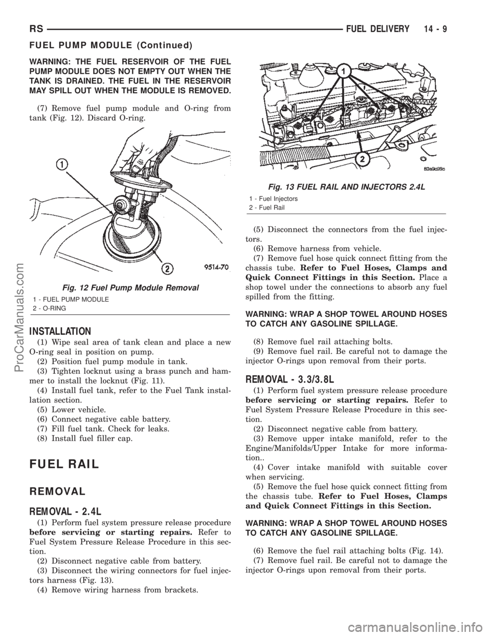
(7) Remove fuel pump module and O-ring from
tank (Fig. 12). Discard O-ring.
INSTALLATION
(1) Wipe seal area of tank clean and place a new
O-ring seal in position on pump.
(2) Position fuel pump module in tank.
(3) Tighten locknut using a brass punch and ham-
mer to install the locknut (Fig. 11).
(4) Install fuel tank, refer to the Fuel Tank instal-
lation section.
(5) Lower vehicle.
(6) Connect negative cable battery.
(7) Fill fuel tank. Check for leaks.
(8) Install fuel filler cap.
FUEL RAIL
REMOVAL
REMOVAL - 2.4L
(1) Perform fuel system pressure release procedure
before servicing or starting repairs.Refer to
Fuel System Pressure Release Procedure in this sec-
tion.
(2) Disconnect negative cable from battery.
(3) Disconnect the wiring connectors for fuel injec-
tors harness (Fig. 13).
(4) Remove wiring harness from brackets.(5) Disconnect the connectors from the fuel injec-
tors.
(6) Remove harness from vehicle.
(7) Remove fuel hose quick connect fitting from the
chassis tube.Refer to Fuel Hoses, Clamps and
Quick Connect Fittings in this Section.Place a
shop towel under the connections to absorb any fuel
spilled from the fitting.
WARNING: WRAP A SHOP TOWEL AROUND HOSES
TO CATCH ANY GASOLINE SPILLAGE.
(8) Remove fuel rail attaching bolts.
(9) Remove fuel rail. Be careful not to damage the
injector O-rings upon removal from their ports.
REMOVAL - 3.3/3.8L
(1) Perform fuel system pressure release procedure
before servicing or starting repairs.Refer to
Fuel System Pressure Release Procedure in this sec-
tion.
(2) Disconnect negative cable from battery.
(3) Remove upper intake manifold, refer to the
Engine/Manifolds/Upper Intake for more informa-
tion..
(4) Cover intake manifold with suitable cover
when servicing.
(5) Remove the fuel hose quick connect fitting from
the chassis tube.Refer to Fuel Hoses, Clamps
and Quick Connect Fittings in this Section.
WARNING: WRAP A SHOP TOWEL AROUND HOSES
TO CATCH ANY GASOLINE SPILLAGE.
(6) Remove the fuel rail attaching bolts (Fig. 14).
(7) Remove fuel rail. Be careful not to damage the
injector O-rings upon removal from their ports.
Fig. 12 Fuel Pump Module Removal
1 - FUEL PUMP MODULE
2 - O-RING
Fig. 13 FUEL RAIL AND INJECTORS 2.4L
1 - Fuel Injectors
2 - Fuel Rail
RSFUEL DELIVERY14-9
FUEL PUMP MODULE (Continued)
ProCarManuals.com
Page 1462 of 2399

REMOVAL
(1) Remove fuel filler cap and perform Fuel Sys-
tem Pressure Release procedure (Fig. 15).
(2) Disconnect negative cable from battery.
(3) Insert fuel siphon hose into fuel filler neck and
push it into the tank.
(4) Drain fuel tank dry into holding tank or a
properly labeledGASOLINEsafety container.
(5) Raise vehicle on hoist and support.
(6) Use a transmission jack to support fuel tank.
Remove bolts from fuel tank straps.
(7) Lower tank slightly.
(8) Disconnect the fuel filler vent tube. Squeeze
tabs and pull apart (Fig. 16).
(9) Disconnect the fuel fill hose at the fuel tank
filler metal tubeNOT AT THE FUEL TANK(Fig.
16).
(10) Disconnect fuel line and vapor line at the
front of the fuel tank.
The fuel pump module electrical connector
has a retainer that locks it in place.
(11) Slide fuel pump module electrical connector
lock to unlock (Fig. 17).
(12) Push down on connector retainer (Fig. 18) and
pull connector off module.
(13) Lower tank from vehicle. Remove fuel filler
vent tube from frame (Fig. 19).
INSTALLATION
(1) Position fuel tank on transmission jack. Con-
nect rollover valve hose. Connect fuel filler tube vent
hose and tighten clamp.
(2) Raise tank into position and carefully work
filler metal tube into the rubber hose on fuel tank. A
light coating of clean engine oil on the tube end may
be used to aid assembly.
Fig. 15 Fuel Tank
1 - ROLLOVER VALVE
2 - FUEL FILLER INLET
3 - ROLLOVER VALVE
4 - GROUND STRAP
5 - FUEL FILTER
6 - FUEL PUMP MODULEFig. 16 FUEL FILLER AND VENT TUBE
1 - Filler Tube
2 - Vent Tube
Fig. 17 Fuel Line Retainers and Pump Connector
Lock
1 - PUSH
2 - CONNECTOR LOCK
3 - QUICK CONNECT RETAINERS
RSFUEL DELIVERY14-11
FUEL TANK (Continued)
ProCarManuals.com
Page 2303 of 2399

PLUMBING - FRONT
WARNING
WARNING
WARNING: DO NOT OPERATE DCHA IN AN
ENCLOSED AREA SUCH AS A GARAGE THAT
DOES NOT HAVE EXHAUST VENTILATION FACILI-
TIES. ALWAYS VENT THE DCHA'S EXHAUST WHEN
OPERATING THE DCHA. FAILURE TO FOLLOW
THESE INSTRUCTION MAY RESULT IN PERSONAL
INJURY OR DEATH.
ALLOW THE DCHA ASSEMBLY TO COOL BEFORE
PERFORMING A COMPONENT INSPECTION/RE-
PAIR/REPLACEMENT. FAILURE TO FOLLOW THESE
INSTRUCTIONS MY RESULT IN PERSONAL INJURY.
VERIFY THAT ALL DCHA FUEL LINES ARE
SECURELY FASTENED TO THEIR RESPECTIVE
COMPONENTS BEFORE THIS PROCEDURE.
WARNING
WARNING:: THE ENGINE COOLING SYSTEM IS
DESIGNED TO DEVELOP INTERNAL PRESSURES
OF 97 TO 123 KILOPASCALS (14 TO 18 POUNDS
PER SQUARE INCH). DO NOT REMOVE OR
LOOSEN THE COOLANT PRESSURE CAP, CYLIN-
DER BLOCK DRAIN PLUGS, RADIATOR DRAIN,
RADIATOR HOSES, HEATER HOSES, OR HOSE
CLAMPS WHILE THE SYSTEM IS HOT AND UNDER
PRESSURE. FAILURE TO OBSERVE THIS WARNING
CAN RESULT IN SERIOUS BURNS FROM THE
HEATED ENGINE COOLANT. ALLOW THE VEHICLE
TO COOL FOR A MINIMUM OF 15 MINUTES
BEFORE OPENING THE COOLING SYSTEM FOR
SERVICE.
WARNING: THE ENGINE COOLING SYSTEM CON-
TAINS ANTIFREEZE. ANTIFREEZE IS AN ETHYLENE
GLYCOL BASED COOLANT AND IS HARMFUL IF
SWALLOWED OR IF THE VAPORS ARE INHALED. IF
SWALLOWED, DRINK TWO GLASSES OF WATER
AND INDUCE VOMITING. IF VAPORS ARE INHALED,
MOVE TO AN AREA FOR FRESH AIR. SEEK MEDI-
CAL ATTENTION IMMEDIATELY. DO NOT STORE IN
OPEN OR UNMARKED CONTAINERS. WASH SKIN
AND CLOTHING THOROUGHLY AFTER COMING IN
CONTACT WITH ETHYLENE GLYCOL. KEEP OUT
OF REACH OF CHILDREN.
WARNING: DISPOSE OF ETHYLENE GLYCOL
BASED COOLANT PROPERLY. CONTACT YOURDEALER OR A LOCAL GOVERNMENT AGENCY FOR
THE LOCATION OF AN APPROVED ETHYLENE GLY-
COL COLLECTION AND/OR RECYCLING CENTER IN
YOUR AREA.
WARNING - A/C PLUMBING
WARNING:: THE AIR CONDITIONING SYSTEM CON-
TAINS REFRIGERANT UNDER HIGH PRESSURE.
SEVERE PERSONAL INJURY MAY RESULT FROM
IMPROPER SERVICE PROCEDURES. REPAIRS
SHOULD ONLY BE PERFORMED BY QUALIFIED
SERVICE PERSONNEL.
WARNING: AVOID BREATHING THE REFRIGERANT
AND REFRIGERANT OIL VAPOR OR MIST. EXPO-
SURE MAY IRRITATE THE EYES, NOSE, AND/OR
THROAT. WEAR EYE PROTECTION WHEN SERVIC-
ING THE AIR CONDITIONING REFRIGERANT SYS-
TEM. SERIOUS EYE INJURY CAN RESULT FROM
DIRECT CONTACT WITH THE REFRIGERANT. IF
EYE CONTACT OCCURS, SEEK MEDICAL ATTEN-
TION IMMEDIATELY.
WARNING: DO NOT EXPOSE THE REFRIGERANT
TO OPEN FLAME. POISONOUS GAS IS CREATED
WHEN REFRIGERANT IS BURNED. AN ELEC-
TRONIC LEAK DETECTOR IS RECOMMENDED.
WARNING: IF ACCIDENTAL SYSTEM DISCHARGE
OCCURS, VENTILATE THE WORK AREA BEFORE
RESUMING SERVICE. LARGE AMOUNTS OF
REFRIGERANT RELEASED IN A CLOSED WORK
AREA WILL DISPLACE THE OXYGEN AND CAUSE
SUFFOCATION.
WARNING: THE EVAPORATION RATE OF R-134a
REFRIGERANT AT AVERAGE TEMPERATURE AND
ALTITUDE IS EXTREMELY HIGH. AS A RESULT,
ANYTHING THAT COMES IN CONTACT WITH THE
REFRIGERANT WILL FREEZE. ALWAYS PROTECT
THE SKIN OR DELICATE OBJECTS FROM DIRECT
CONTACT WITH THE REFRIGERANT.
WARNING: THE R-134a SERVICE EQUIPMENT OR
THE VEHICLE REFRIGERANT SYSTEM SHOULD
NOT BE PRESSURE TESTED OR LEAK TESTED
WITH COMPRESSED AIR. SOME MIXTURES OF AIR
AND R-134a HAVE BEEN SHOWN TO BE COMBUS-
TIBLE AT ELEVATED PRESSURES. THESE MIX-
TURES ARE POTENTIALLY DANGEROUS, AND MAY
RESULT IN FIRE OR EXPLOSION CAUSING INJURY
OR PROPERTY DAMAGE.
24 - 60 PLUMBING - FRONTRS
ProCarManuals.com
Page 2372 of 2399
EVAP/PURGE SOLENOID
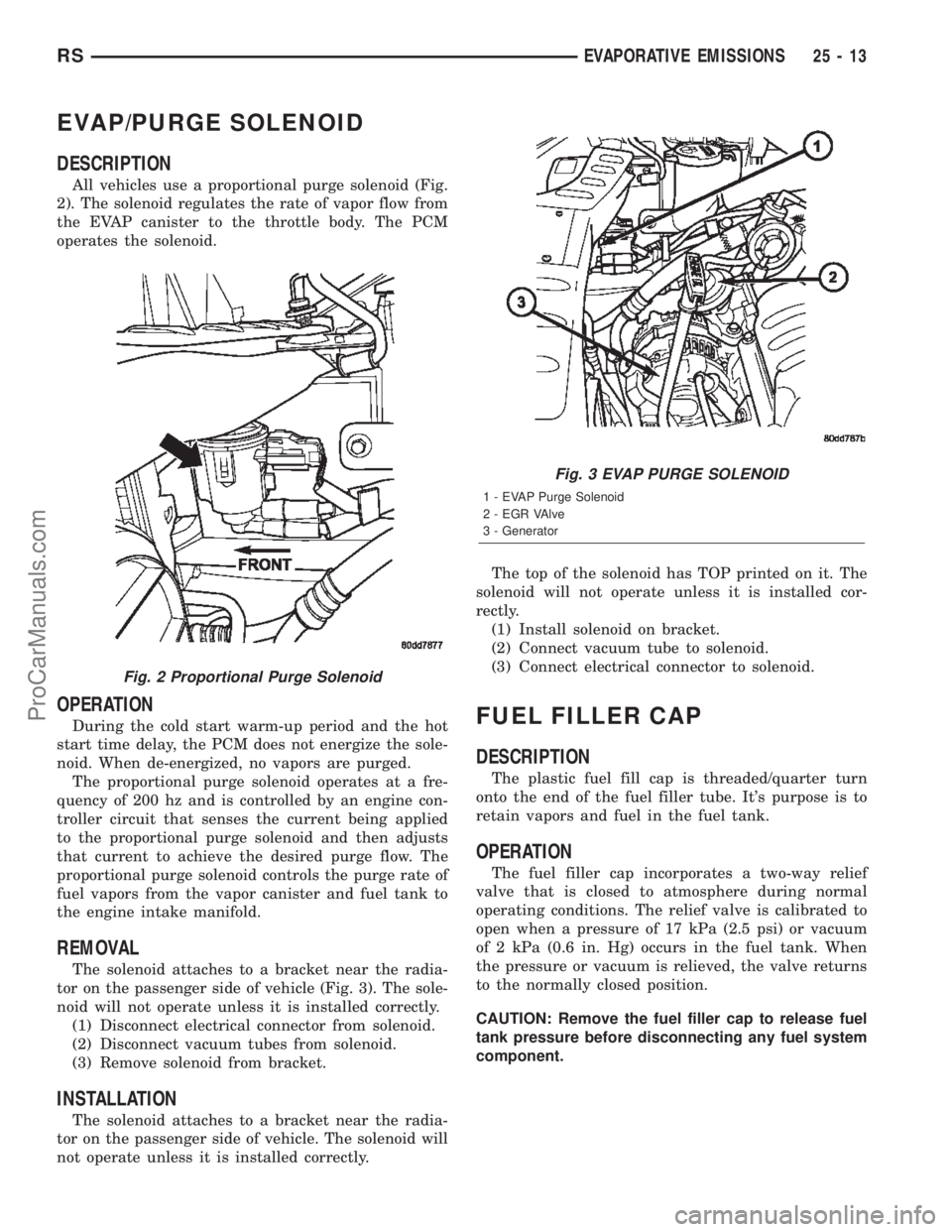
DESCRIPTION
All vehicles use a proportional purge solenoid (Fig.
2). The solenoid regulates the rate of vapor flow from
the EVAP canister to the throttle body. The PCM
operates the solenoid.
OPERATION
During the cold start warm-up period and the hot
start time delay, the PCM does not energize the sole-
noid. When de-energized, no vapors are purged.
The proportional purge solenoid operates at a fre-
quency of 200 hz and is controlled by an engine con-
troller circuit that senses the current being applied
to the proportional purge solenoid and then adjusts
that current to achieve the desired purge flow. The
proportional purge solenoid controls the purge rate of
fuel vapors from the vapor canister and fuel tank to
the engine intake manifold.
REMOVAL
The solenoid attaches to a bracket near the radia-
tor on the passenger side of vehicle (Fig. 3). The sole-
noid will not operate unless it is installed correctly.
(1) Disconnect electrical connector from solenoid.
(2) Disconnect vacuum tubes from solenoid.
(3) Remove solenoid from bracket.
INSTALLATION
The solenoid attaches to a bracket near the radia-
tor on the passenger side of vehicle. The solenoid will
not operate unless it is installed correctly.The top of the solenoid has TOP printed on it. The
solenoid will not operate unless it is installed cor-
rectly.
(1) Install solenoid on bracket.
(2) Connect vacuum tube to solenoid.
(3) Connect electrical connector to solenoid.
FUEL FILLER CAP
DESCRIPTION
The plastic fuel fill cap is threaded/quarter turn
onto the end of the fuel filler tube. It's purpose is to
retain vapors and fuel in the fuel tank.
OPERATION
The fuel filler cap incorporates a two-way relief
valve that is closed to atmosphere during normal
operating conditions. The relief valve is calibrated to
open when a pressure of 17 kPa (2.5 psi) or vacuum
of 2 kPa (0.6 in. Hg) occurs in the fuel tank. When
the pressure or vacuum is relieved, the valve returns
to the normally closed position.
CAUTION: Remove the fuel filler cap to release fuel
tank pressure before disconnecting any fuel system
component.
Fig. 2 Proportional Purge Solenoid
Fig. 3 EVAP PURGE SOLENOID
1 - EVAP Purge Solenoid
2 - EGR VAlve
3 - Generator
RSEVAPORATIVE EMISSIONS25-13
ProCarManuals.com