steering CHRYSLER VOYAGER 2002 Manual PDF
[x] Cancel search | Manufacturer: CHRYSLER, Model Year: 2002, Model line: VOYAGER, Model: CHRYSLER VOYAGER 2002Pages: 2399, PDF Size: 57.96 MB
Page 261 of 2399
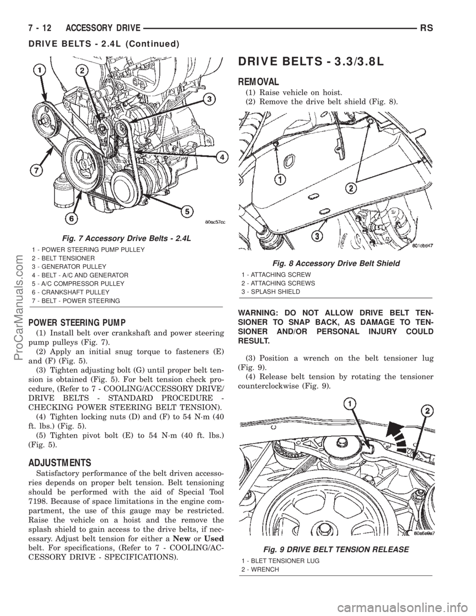
POWER STEERING PUMP
(1) Install belt over crankshaft and power steering
pump pulleys (Fig. 7).
(2) Apply an initial snug torque to fasteners (E)
and (F) (Fig. 5).
(3) Tighten adjusting bolt (G) until proper belt ten-
sion is obtained (Fig. 5). For belt tension check pro-
cedure, (Refer to 7 - COOLING/ACCESSORY DRIVE/
DRIVE BELTS - STANDARD PROCEDURE -
CHECKING POWER STEERING BELT TENSION).
(4) Tighten locking nuts (D) and (F) to 54 N´m (40
ft. lbs.) (Fig. 5).
(5) Tighten pivot bolt (E) to 54 N´m (40 ft. lbs.)
(Fig. 5).
ADJUSTMENTS
Satisfactory performance of the belt driven accesso-
ries depends on proper belt tension. Belt tensioning
should be performed with the aid of Special Tool
7198. Because of space limitations in the engine com-
partment, the use of this gauge may be restricted.
Raise the vehicle on a hoist and the remove the
splash shield to gain access to the drive belts, if nec-
essary. Adjust belt tension for either aNeworUsed
belt. For specifications, (Refer to 7 - COOLING/AC-
CESSORY DRIVE - SPECIFICATIONS).
DRIVE BELTS - 3.3/3.8L
REMOVAL
(1) Raise vehicle on hoist.
(2) Remove the drive belt shield (Fig. 8).
WARNING: DO NOT ALLOW DRIVE BELT TEN-
SIONER TO SNAP BACK, AS DAMAGE TO TEN-
SIONER AND/OR PERSONAL INJURY COULD
RESULT.
(3) Position a wrench on the belt tensioner lug
(Fig. 9).
(4) Release belt tension by rotating the tensioner
counterclockwise (Fig. 9).
Fig. 7 Accessory Drive Belts - 2.4L
1 - POWER STEERING PUMP PULLEY
2 - BELT TENSIONER
3 - GENERATOR PULLEY
4 - BELT - A/C AND GENERATOR
5 - A/C COMPRESSOR PULLEY
6 - CRANKSHAFT PULLEY
7 - BELT - POWER STEERING
Fig. 8 Accessory Drive Belt Shield
1 - ATTACHING SCREW
2 - ATTACHING SCREWS
3 - SPLASH SHIELD
Fig. 9 DRIVE BELT TENSION RELEASE
1 - BLET TENSIONER LUG
2 - WRENCH
7 - 12 ACCESSORY DRIVERS
DRIVE BELTS - 2.4L (Continued)
ProCarManuals.com
Page 262 of 2399
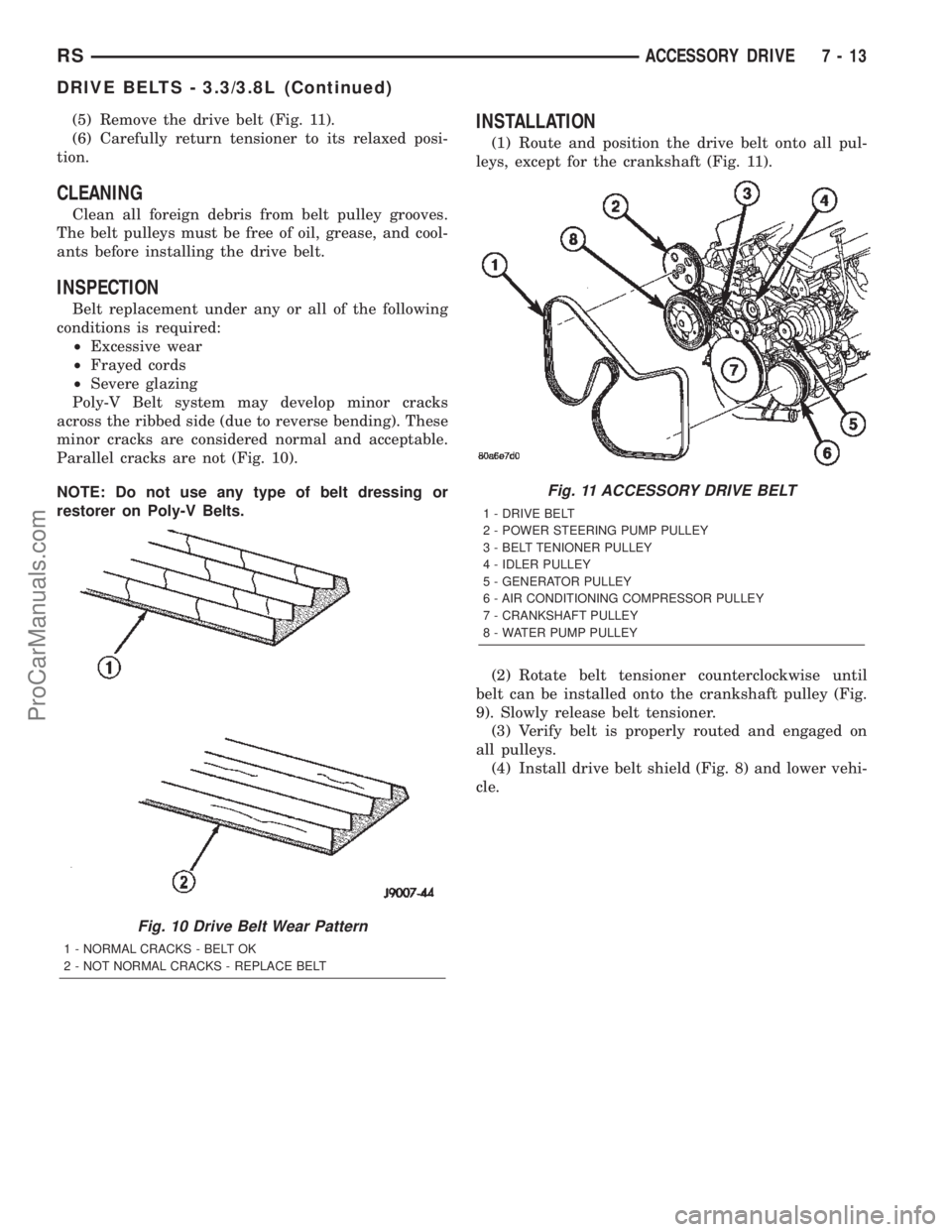
(5) Remove the drive belt (Fig. 11).
(6) Carefully return tensioner to its relaxed posi-
tion.
CLEANING
Clean all foreign debris from belt pulley grooves.
The belt pulleys must be free of oil, grease, and cool-
ants before installing the drive belt.
INSPECTION
Belt replacement under any or all of the following
conditions is required:
²Excessive wear
²Frayed cords
²Severe glazing
Poly-V Belt system may develop minor cracks
across the ribbed side (due to reverse bending). These
minor cracks are considered normal and acceptable.
Parallel cracks are not (Fig. 10).
NOTE: Do not use any type of belt dressing or
restorer on Poly-V Belts.
INSTALLATION
(1) Route and position the drive belt onto all pul-
leys, except for the crankshaft (Fig. 11).
(2) Rotate belt tensioner counterclockwise until
belt can be installed onto the crankshaft pulley (Fig.
9). Slowly release belt tensioner.
(3) Verify belt is properly routed and engaged on
all pulleys.
(4) Install drive belt shield (Fig. 8) and lower vehi-
cle.
Fig. 10 Drive Belt Wear Pattern
1 - NORMAL CRACKS - BELT OK
2 - NOT NORMAL CRACKS - REPLACE BELT
Fig. 11 ACCESSORY DRIVE BELT
1 - DRIVE BELT
2 - POWER STEERING PUMP PULLEY
3 - BELT TENIONER PULLEY
4 - IDLER PULLEY
5 - GENERATOR PULLEY
6 - AIR CONDITIONING COMPRESSOR PULLEY
7 - CRANKSHAFT PULLEY
8 - WATER PUMP PULLEY
RSACCESSORY DRIVE7-13
DRIVE BELTS - 3.3/3.8L (Continued)
ProCarManuals.com
Page 271 of 2399
ENGINE COOLANT
TEMPERATURE SENSOR -
3.3/3.8L
DESCRIPTION
The engine coolant temperature sensor threads
into a coolant passage on lower intake manifold near
the thermostat (Fig. 6). New sensors have sealant
applied to the threads.
REMOVAL
WARNING: HOT, PRESSURIZED COOLANT CAN
CAUSE INJURY BY SCALDING. COOLING SYSTEM
MUST BE PARTIALLY DRAINED BEFORE REMOV-
ING THE COOLANT TEMPERATURE SENSOR.
(1) Drain cooling system below engine coolant tem-
perature sensor level. (Refer to 7 - COOLING -
STANDARD PROCEDURE)
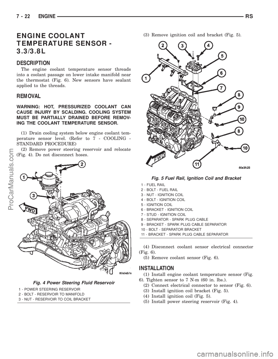
(2) Remove power steering reservoir and relocate
(Fig. 4). Do not disconnect hoses.(3) Remove ignition coil and bracket (Fig. 5).
(4) Disconnect coolant sensor electrical connector
(Fig. 6).
(5) Remove coolant sensor (Fig. 6).
INSTALLATION
(1) Install engine coolant temperature sensor (Fig.
6). Tighten sensor to 7 N´m (60 in. lbs.).
(2) Connect electrical connector to sensor (Fig. 6).
(3) Install ignition coil bracket (Fig. 5).
(4) Install ignition coil (Fig. 5).
(5) Install power steering reservoir (Fig. 4).
Fig. 4 Power Steering Fluid Reservoir
1 - POWER STEERING RESERVOIR
2 - BOLT - RESERVOIR TO MANIFOLD
3 - NUT - RESERVOIR TO COIL BRACKET
Fig. 5 Fuel Rail, Ignition Coil and Bracket
1 - FUEL RAIL
2 - BOLT - FUEL RAIL
3 - NUT - IGNITION COIL
4 - BOLT - IGNITION COIL
5 - IGNITION COIL
6 - BRACKET - IGNITION COIL
7 - STUD - IGNITION COIL
8 - SEPARATOR - SPARK PLUG CABLE
9 - BRACKET - SPARK PLUG CABLE SEPARATOR
10 - BOLT - SEPARATOR BRACKET
11 - BRACKET - SPARK PLUG CABLE SEPARATOR
7 - 22 ENGINERS
ProCarManuals.com
Page 298 of 2399
ACCESSORY DRIVE
TABLE OF CONTENTS
page page
ACCESSORY DRIVE
SPECIFICATIONS - ACCESSORY BELT
TENSION.............................9
BELT TENSIONER
REMOVAL.............................9
INSTALLATION..........................9
IDLER PULLEY
REMOVAL.............................10
INSTALLATION.........................10
DRIVE BELTS
DESCRIPTION
DESCRIPTION - ACCESSORY DRIVE BELT . 10DESCRIPTION - POWER STEERING BELT . . 10
OPERATION
OPERATION-ACCESSORY DRIVE BELT....10
OPERATION-POWER STEERING BELT.....10
DIAGNOSIS AND TESTING - ACCESSORY
DRIVE BELT.........................11
REMOVAL
REMOVAL-ACCESSORY DRIVE BELT......11
REMOVAL...........................11
INSTALLATION
INSTALLATION-ACCESSORY DRIVE BELT . . 13
INSTALLATION-POWER STEERING BELT . . . 13
ACCESSORY DRIVE
SPECIFICATIONS - ACCESSORY BELT TENSION
ACCESSORY DRIVE
BELTGAUGE
2.5L DIESEL ENGINE
A/C Compressor/
GeneratorDynamic Tensioner
Power Steering Belt 300 N (67 lbs.)
BELT TENSIONER
REMOVAL
WARNING:: BECAUSE OF HIGH SPRING TENSION,
DO NOT ATTEMPT TO DISASSEMBLE THE AUTO-
MATIC BELT TENSIONER. THE TENSIONER IS SER-
VICED AS AN ASSEMBLY.
(1) Remove the power steering belt (Refer to 7 -
COOLING/ACCESSORY DRIVE/DRIVE BELTS -
REMOVAL).
(2) Remove the accessory drive belt (Refer to 7 -
COOLING/ACCESSORY DRIVE/DRIVE BELTS -
INSTALLATION).
(3) Remove the belt tensioner retaining bolt and
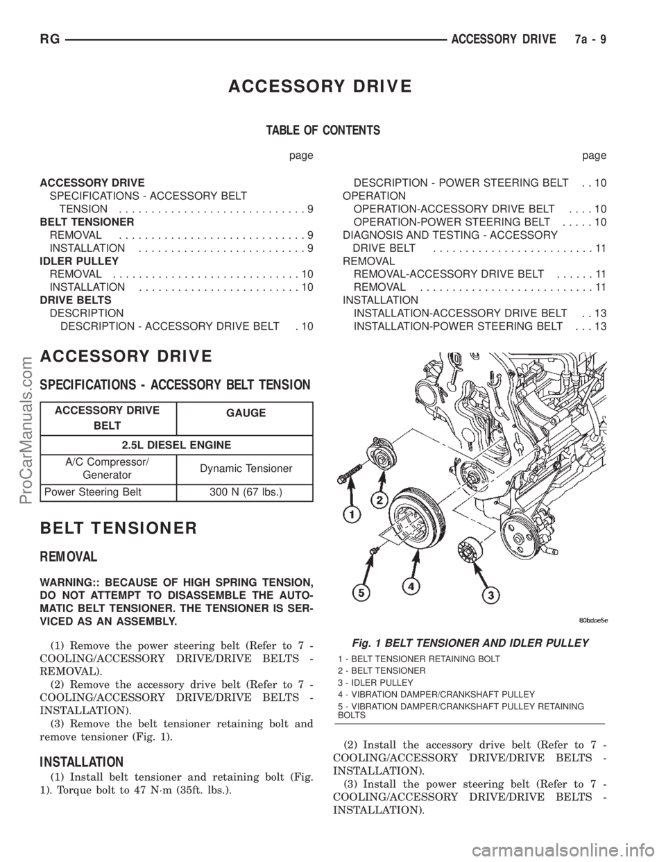
remove tensioner (Fig. 1).
INSTALLATION
(1) Install belt tensioner and retaining bolt (Fig.
1). Torque bolt to 47 N´m (35ft. lbs.).(2) Install the accessory drive belt (Refer to 7 -
COOLING/ACCESSORY DRIVE/DRIVE BELTS -
INSTALLATION).
(3) Install the power steering belt (Refer to 7 -
COOLING/ACCESSORY DRIVE/DRIVE BELTS -
INSTALLATION).
Fig. 1 BELT TENSIONER AND IDLER PULLEY
1 - BELT TENSIONER RETAINING BOLT
2 - BELT TENSIONER
3 - IDLER PULLEY
4 - VIBRATION DAMPER/CRANKSHAFT PULLEY
5 - VIBRATION DAMPER/CRANKSHAFT PULLEY RETAINING
BOLTS
RGACCESSORY DRIVE7a-9
ProCarManuals.com
Page 299 of 2399

IDLER PULLEY
REMOVAL
(1) Remove the accessory drive belt (Refer to 7 -
COOLING/ACCESSORY DRIVE/DRIVE BELTS -
REMOVAL).
CAUTION: IDLER PULLEY RETAINING BOLT HAS
LEFT HAND THREAD
(2) Remove the idler pulley (Fig. 2).
INSTALLATION
(1) Install the idler pulley (Fig. 2). Torque retain-
ing bolt to 22 N´m (16 ft. lbs.).
(2) Install the accessory drive belt (Refer to 7 -
COOLING/ACCESSORY DRIVE/DRIVE BELTS -
INSTALLATION).
(3) Install the power steering belt (Refer to 7 -
COOLING/ACCESSORY DRIVE/DRIVE BELTS -
INSTALLATION).
DRIVE BELTS
DESCRIPTION
DESCRIPTION - ACCESSORY DRIVE BELT
The accessory drive belt is a serpentine type belt
(Fig. 3). Satisfactory performance of these belts
depends on belt condition and proper belt tension.
DESCRIPTION - POWER STEERING BELT
The power steering belt is a serpentine type belt
(Fig. 3). Satisfactory performance of this belt depends
on condition of the belt.
OPERATION
OPERATION-ACCESSORY DRIVE BELT
The accessory drive belts form the link between
the engine crankshaft and the engine driven accesso-
ries.
OPERATION-POWER STEERING BELT
The power steering belt forms a link between the
engine crankshaft and the power steering pump.
Fig. 2 BELT TENSIONER AND IDLER PULLEY
1 - BELT TENSIONER RETAINING BOLT
2 - BELT TENSIONER
3 - IDLER PULLEY
4 - VIBRATION DAMPER/CRANKSHAFT PULLEY
5 - VIBRATION DAMPER/CRANKSHAFT PULLEY RETAINING
BOLTS
Fig. 3 ACCESSORY DRIVE BELT ROUTING
1 - GENERATOR
2 - IDLER PULLEY
3 - A/C COMPRESSOR CLUTCH
4 - POWER STEERING PUMP PULLEY
5 - POWER STEERING BELT
6 - CRANKSHAFT DAMPER/PULLEY
7 - BELT TENSIONER
8 - ACCESSORY DRIVE BELT
7a - 10 ACCESSORY DRIVERG
ProCarManuals.com
Page 300 of 2399
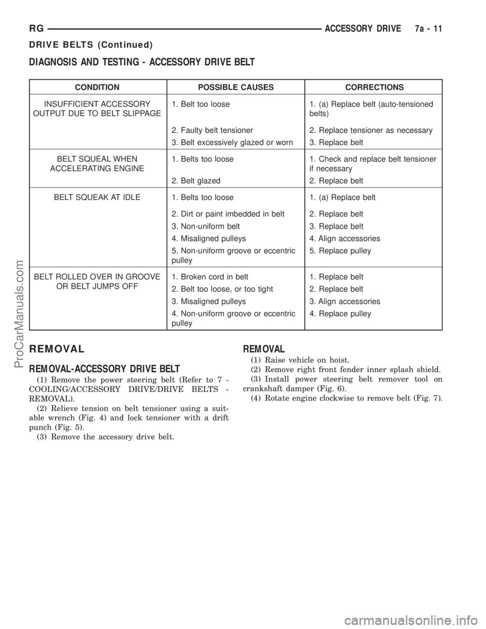
DIAGNOSIS AND TESTING - ACCESSORY DRIVE BELT
CONDITION POSSIBLE CAUSES CORRECTIONS
INSUFFICIENT ACCESSORY
OUTPUT DUE TO BELT SLIPPAGE1. Belt too loose 1. (a) Replace belt (auto-tensioned
belts)
2. Faulty belt tensioner 2. Replace tensioner as necessary
3. Belt excessively glazed or worn 3. Replace belt
BELT SQUEAL WHEN
ACCELERATING ENGINE1. Belts too loose 1. Check and replace belt tensioner
if necessary
2. Belt glazed 2. Replace belt
BELT SQUEAK AT IDLE 1. Belts too loose 1. (a) Replace belt
2. Dirt or paint imbedded in belt 2. Replace belt
3. Non-uniform belt 3. Replace belt
4. Misaligned pulleys 4. Align accessories
5. Non-uniform groove or eccentric
pulley5. Replace pulley
BELT ROLLED OVER IN GROOVE
OR BELT JUMPS OFF1. Broken cord in belt 1. Replace belt
2. Belt too loose, or too tight 2. Replace belt
3. Misaligned pulleys 3. Align accessories
4. Non-uniform groove or eccentric
pulley4. Replace pulley
REMOVAL
REMOVAL-ACCESSORY DRIVE BELT
(1) Remove the power steering belt (Refer to 7 -
COOLING/ACCESSORY DRIVE/DRIVE BELTS -
REMOVAL).
(2) Relieve tension on belt tensioner using a suit-
able wrench (Fig. 4) and lock tensioner with a drift
punch (Fig. 5).
(3) Remove the accessory drive belt.
REMOVAL
(1) Raise vehicle on hoist.
(2) Remove right front fender inner splash shield.
(3) Install power steering belt remover tool on
crankshaft damper (Fig. 6).
(4) Rotate engine clockwise to remove belt (Fig. 7).
RGACCESSORY DRIVE7a-11
DRIVE BELTS (Continued)
ProCarManuals.com
Page 301 of 2399

Fig. 4 ACCESSORY DRIVE BELT REMOVAL
1 - BELT TENSIONER
2 - ACCESSORY DRIVE BELT
3 - IDLER PULLEY
4 - A/C COMPRESSOR CLUTCH
5 - CRANKSHAFT DAMPER/PULLEY
6 - WRENCH
Fig. 5 LOCKING/LOCKING BELT TENSIONER
Fig. 6 POWER STEERING BELT REMOVAL TOOL
1 - VIBRATION DAMPER
2 - POWER STEERING PULLEY
3 - POWER STEERING BELT
4 - POWER STEERING BELT REMOVER
Fig. 7 POWER STEERING BELT REMOVAL
1 - VIBRATION DAMPER
2 - POWER STEERING BELT
3 - POPWER STEERING BELT REMOVER
7a - 12 ACCESSORY DRIVERG
DRIVE BELTS (Continued)
ProCarManuals.com
Page 302 of 2399

INSTALLATION
INSTALLATION-ACCESSORY DRIVE BELT
(1) Install the accessory drive belt in proper popsi-
tion (Fig. 8).
(2) Unlock belt tensioner by removing punch and
apply tension to accessory drive belt (Fig. 9).
(3) Install the power steering belt (Refer to 7 -
COOLING/ACCESSORY DRIVE/DRIVE BELTS -
INSTALLATION).
INSTALLATION-POWER STEERING BELT
(1) Install power steering belt installation tool
(Fig. 10).
(2) Install power steering belt on crankshaft and
rotate crankshaft clockwise until belt is fully
installed on crankshaft (Fig. 10).
(3) Remove installation tool from crankshaft.
(4) Install right front fender inner splash shield.
(5) Lower vehicle from hoist.
Fig. 8 ACCESSORY DRIVE BELT ROUTING
1 - GENERATOR
2 - IDLER PULLEY
3 - A/C COMPRESSOR CLUTCH
4 - POWER STEERING PUMP PULLEY
5 - POWER STEERING BELT
6 - CRANKSHAFT DAMPER/PULLEY
7 - BELT TENSIONER
8 - ACCESSORY DRIVE BELT
Fig. 9 LOCKING/UNLOCKING BELT TENSIONER
Fig. 10 POWER STEERING BELT INSTALLATION
1 - POWER STEERING BELT
2 - HOLDING HOOK
3 - POWER STEERING PUMP PULLEY
4 - VIBRATION DAMPER
5 - POWER STEERING BELT INSTALLATION TOOL
RGACCESSORY DRIVE7a-13
DRIVE BELTS (Continued)
ProCarManuals.com
Page 321 of 2399
information and location views for the various wire
harness connectors, splices and grounds.
WARNING: ON VEHICLES EQUIPPED WITH AIR-
BAGS, REFER TO ELECTRICAL, RESTRAINTS
BEFORE ATTEMPTING ANY STEERING WHEEL,STEERING COLUMN, OR INSTRUMENT PANEL
COMPONENT DIAGNOSIS OR SERVICE. FAILURE
TO TAKE THE PROPER PRECAUTIONS COULD
RESULT IN ACCIDENTAL AIRBAG DEPLOYMENT
AND POSSIBLE PERSONAL INJURY.
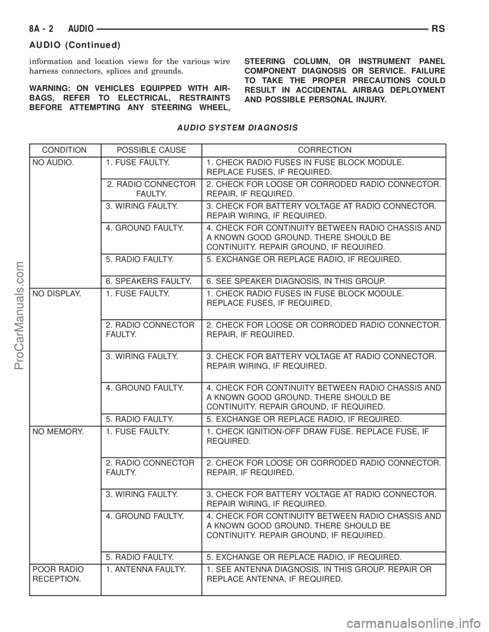
AUDIO SYSTEM DIAGNOSIS
CONDITION POSSIBLE CAUSE CORRECTION
NO AUDIO. 1. FUSE FAULTY. 1. CHECK RADIO FUSES IN FUSE BLOCK MODULE.
REPLACE FUSES, IF REQUIRED.
2. RADIO CONNECTOR
FAULTY.2. CHECK FOR LOOSE OR CORRODED RADIO CONNECTOR.
REPAIR, IF REQUIRED.
3. WIRING FAULTY. 3. CHECK FOR BATTERY VOLTAGE AT RADIO CONNECTOR.
REPAIR WIRING, IF REQUIRED.
4. GROUND FAULTY. 4. CHECK FOR CONTINUITY BETWEEN RADIO CHASSIS AND
A KNOWN GOOD GROUND. THERE SHOULD BE
CONTINUITY. REPAIR GROUND, IF REQUIRED.
5. RADIO FAULTY. 5. EXCHANGE OR REPLACE RADIO, IF REQUIRED.
6. SPEAKERS FAULTY. 6. SEE SPEAKER DIAGNOSIS, IN THIS GROUP.
NO DISPLAY. 1. FUSE FAULTY. 1. CHECK RADIO FUSES IN FUSE BLOCK MODULE.
REPLACE FUSES, IF REQUIRED.
2. RADIO CONNECTOR
FAULTY.2. CHECK FOR LOOSE OR CORRODED RADIO CONNECTOR.
REPAIR, IF REQUIRED.
3. WIRING FAULTY. 3. CHECK FOR BATTERY VOLTAGE AT RADIO CONNECTOR.
REPAIR WIRING, IF REQUIRED.
4. GROUND FAULTY. 4. CHECK FOR CONTINUITY BETWEEN RADIO CHASSIS AND
A KNOWN GOOD GROUND. THERE SHOULD BE
CONTINUITY. REPAIR GROUND, IF REQUIRED.
5. RADIO FAULTY. 5. EXCHANGE OR REPLACE RADIO, IF REQUIRED.
NO MEMORY. 1. FUSE FAULTY. 1. CHECK IGNITION-OFF DRAW FUSE. REPLACE FUSE, IF
REQUIRED.
2. RADIO CONNECTOR
FAULTY.2. CHECK FOR LOOSE OR CORRODED RADIO CONNECTOR.
REPAIR, IF REQUIRED.
3. WIRING FAULTY. 3. CHECK FOR BATTERY VOLTAGE AT RADIO CONNECTOR.
REPAIR WIRING, IF REQUIRED.
4. GROUND FAULTY. 4. CHECK FOR CONTINUITY BETWEEN RADIO CHASSIS AND
A KNOWN GOOD GROUND. THERE SHOULD BE
CONTINUITY. REPAIR GROUND, IF REQUIRED.
5. RADIO FAULTY. 5. EXCHANGE OR REPLACE RADIO, IF REQUIRED.
POOR RADIO
RECEPTION.1. ANTENNA FAULTY. 1. SEE ANTENNA DIAGNOSIS, IN THIS GROUP. REPAIR OR
REPLACE ANTENNA, IF REQUIRED.
8A - 2 AUDIORS
AUDIO (Continued)
ProCarManuals.com
Page 323 of 2399
ANTENNA BODY AND CABLE
DESCRIPTION
All models use a fixed-length stainless steel rod-
type antenna mast, installed at the right front fender
of the vehicle. The antenna mast is connected to the
center wire of the coaxial antenna cable, and is not
grounded to any part of the vehicle.
OPERATION
To minimize static, the antenna base must have a
good ground. The coaxial antenna cable shield (the
outer wire mesh of the cable) is grounded to the
antenna base and the radio chassis.
The antenna coaxial cable has an additional dis-
connect, located near the right end of the instrument
panel. This additional disconnect allows the instru-
ment panel assembly to be removed and installed
without removing the radio.
The factory-installed Electronically Tuned Radios
(ETRs) automatically compensate for radio antenna
trim. Therefore, no antenna trimmer adjustment is
required or possible when replacing the receiver or
the antenna.
DIAGNOSIS AND TESTING - ANTENNA BODY
AND CABLE
WARNING: ON VEHICLES EQUIPPED WITH AIR-
BAGS, REFER TO ELECTRICAL, RESTRAINTS
BEFORE ATTEMPTING ANY STEERING WHEEL,
STEERING COLUMN, OR INSTRUMENT PANEL
COMPONENT DIAGNOSIS OR SERVICE. FAILURE
TO TAKE THE PROPER PRECAUTIONS COULD
RESULT IN ACCIDENTAL AIRBAG DEPLOYMENT
AND POSSIBLE PERSONAL INJURY.
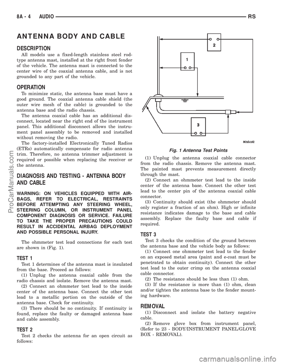
The ohmmeter test lead connections for each test
are shown in (Fig. 1).
TEST 1
Test 1 determines of the antenna mast is insulated
from the base. Proceed as follows:
(1) Unplug the antenna coaxial cable from the
radio chassis and isolate. Remove the antenna mast.
(2) Connect an ohmmeter test lead to the inside
center of the antenna base. Connect the other test
lead to a metallic portion on the outside of the
antenna base. Check for continuity.
(3) There should be no continuity. If continuity is
found, replace the faulty or damaged antenna base
and cable assembly.
TEST 2
Test 2 checks the antenna for an open circuit as
follows:(1) Unplug the antenna coaxial cable connector
from the radio chassis. Remove the antenna mast.
The painted mast prevents measurement directly
through the mast.
(2) Connect an ohmmeter test lead to the inside
center of the antenna base. Connect the other test
lead to the center pin of the antenna coaxial cable
connector.
(3) Continuity should exist (the ohmmeter should
only register a fraction of an ohm). High or infinite
resistance indicates damage to the base and cable
assembly. Replace the faulty base and cable if
required.
TEST 3
Test 3 checks the condition of the ground between
the antenna base and the vehicle body as follows:
(1) Connect one ohmmeter test lead to the fender
on an exposed metal area (paint and e-coat must be
penetrated to obtain continuity). Connect the other
test lead to the outer crimp on the antenna coaxial
cable connector.
(2) The resistance should be less than (1) ohm.
(3) If the resistance is more than (1) ohm, clean
and/or tighten the antenna base to the fender mount-
ing hardware.
REMOVAL
(1) Disconnect and isolate the battery negative
cable.
(2) Remove glove box from instrument panel,
(Refer to 23 - BODY/INSTRUMENT PANEL/GLOVE
BOX - REMOVAL).
Fig. 1 Antenna Test Points
8A - 4 AUDIORS
ProCarManuals.com