steering CHRYSLER VOYAGER 2002 Workshop Manual
[x] Cancel search | Manufacturer: CHRYSLER, Model Year: 2002, Model line: VOYAGER, Model: CHRYSLER VOYAGER 2002Pages: 2399, PDF Size: 57.96 MB
Page 175 of 2399
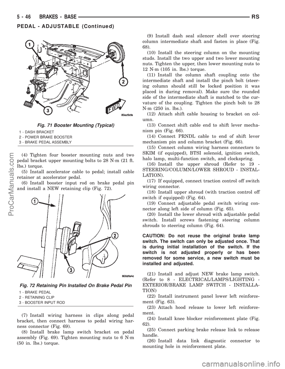
(4) Tighten four booster mounting nuts and two
pedal bracket upper mounting bolts to 28 N´m (21 ft.
lbs.) torque.
(5) Install accelerator cable to pedal; install cable
retainer at accelerator pedal.
(6) Install booster input rod on brake pedal pin
and install a NEW retaining clip (Fig. 72).
(7) Install wiring harness in clips along pedal
bracket, then connect harness to pedal wiring har-
ness connector (Fig. 69).
(8) Install brake lamp switch bracket on pedal
assembly (Fig. 69). Tighten mounting nuts to 6 N´m
(50 in. lbs.) torque.(9) Install dash seal silencer shell over steering
column intermediate shaft and fasten in place (Fig.
68).
(10) Install the steering column on the mounting
studs. Install the two upper and two lower mounting
nuts. Tighten the upper, then lower mounting nuts to
12 N´m (105 in. lbs.) torque.
(11) Install the column shaft coupling onto the
intermediate shaft and install the pinch bolt (steer-
ing column should still be locked position it was
placed in during removal). Make sure the rounded
side of the intermediate shaft is matched to the cur-
vature of the coupling. Tighten the pinch bolt to 28
N´m (250 in. lbs.).
(12) Attach shift cable housing to bracket on col-
umn.
(13) Connect shift cable end to shift lever mecha-
nism pin (Fig. 66).
(14) Connect PRNDL cable to end of shift lever
mechanism pin and column bracket (Fig. 66).
(15) Connect column wiring harness connectors to
SKIM (if equipped), BTSI solenoid, ignition switch,
halo lamp, multi-function switch, and clockspring.
(16) Install the upper shroud (Refer to 19 -
STEERING/COLUMN/LOWER SHROUD - INSTAL-
LATION).
(17) If equipped, connect traction control off switch
wiring connector.
(18) Install upper shroud (with traction control off
switch if equipped) (Fig. 64).
(19) Connect adjustable pedal switch wiring con-
nector along left side of column (Fig. 65).
(20) Install the lower shroud with adjustable pedal
switch. Install screws fastening steering column
shrouds to steering column (Fig. 64).
CAUTION: Do not reuse the original brake lamp
switch. The switch can only be adjusted once. That
is during initial installation of the switch. If the
switch is not adjusted properly or has been
removed for some service, a new switch must be
installed and adjusted.
(21) Install and adjust NEW brake lamp switch.
(Refer to 8 - ELECTRICAL/LAMPS/LIGHTING -
EXTERIOR/BRAKE LAMP SWITCH - INSTALLA-
TION)
(22) Install instrument panel lower left reinforce-
ment (Fig. 63).
(23) Attach hood release to lower left reinforce-
ment.
(24) Install knee blocker reinforcement plate (Fig.
62).
(25) Connect parking brake release link to release
handle.
(26) Install data link diagnostic connector to
mounting hole in reinforcement plate.
Fig. 71 Booster Mounting (Typical)
1 - DASH BRACKET
2 - POWER BRAKE BOOSTER
3 - BRAKE PEDAL ASSEMBLY
Fig. 72 Retaining Pin Installed On Brake Pedal Pin
1 - BRAKE PEDAL
2 - RETAINING CLIP
3 - BOOSTER INPUT ROD
5 - 46 BRAKES - BASERS
PEDAL - ADJUSTABLE (Continued)
ProCarManuals.com
Page 176 of 2399
(27) Install lower steering column cover/knee
blocker (Fig. 62).
(28) Install silencer panel below lower steering col-
umn cover/knee blocker.
NOTE: When reconnecting the battery on a vehicle
that has had the airbag module removed, the fol-
lowing procedure should be used.
(29) Reconnect ground cable to negative post of
battery in following manor:
(a) Connect scan tool (DRBIIIt) to data link
diagnostic connector located below steering column.
(b) Turn ignition key to ON position. Exit vehi-
cle with scan tool leaving scan tool harness
plugged in.
(c) Ensuring that there are no occupants in vehi-
cle, connect ground (-) cable to the negative post of
the battery.
(d) Using scan tool, read and record any airbag
fault codes. Refer to Appropriate Diagnostic Infor-
mation if any faults are found.
(e) Through drivers open window, Reach around
back of steering wheel (between steering wheel and
instrument cluster) and turn ignition key to OFF,
then back ON while observing instrument cluster
airbag indicator lamp. It should go on for six to
eight seconds, then go out. This action indicates
that airbag system is functioning normally. If air-
bag indicator lamp fails to light, blinks on and off,
or goes on and stays on, there is an airbag system
malfunction. Refer to Appropriate Diagnostic Infor-
mation to diagnose the system malfunction.
(30) Using scan tool (DRBIIIt), check for and clear
any existing adjustable pedal fault codes. The adjust-
able pedal system is now activated.
(31) Turn key to OFF and remove scan tool from
vehicle.
(32) Test operation of adjustable pedals, memory
seats (if equipped), RKE (if equipped), and all func-
tions that are steering column operated. If applica-
ble, reset the radio and the clock.
(33) Road test the vehicle to ensure proper opera-
tion of the steering and brake systems.
PEDAL TORQUE SHAFT - RHD
REMOVAL
(1) Remove the instrument panel. (Refer to 23 -
BODY/INSTRUMENT PANEL/INSTRUMENT
PANEL ASSEMBLY - REMOVAL)
(2) Remove the HVAC housing. (Refer to 24 -
HEATING & AIR CONDITIONING/DISTRIBUTION/
HVAC HOUSING - REMOVAL)
(3) Remove the retaining clip at the torque shaft
end of the brake pedal-to-torque shaft link. Removethe link from the torque shaft. Discard the retaining
clip. It is not to be reused. Replace with a new clip
when reassembled.
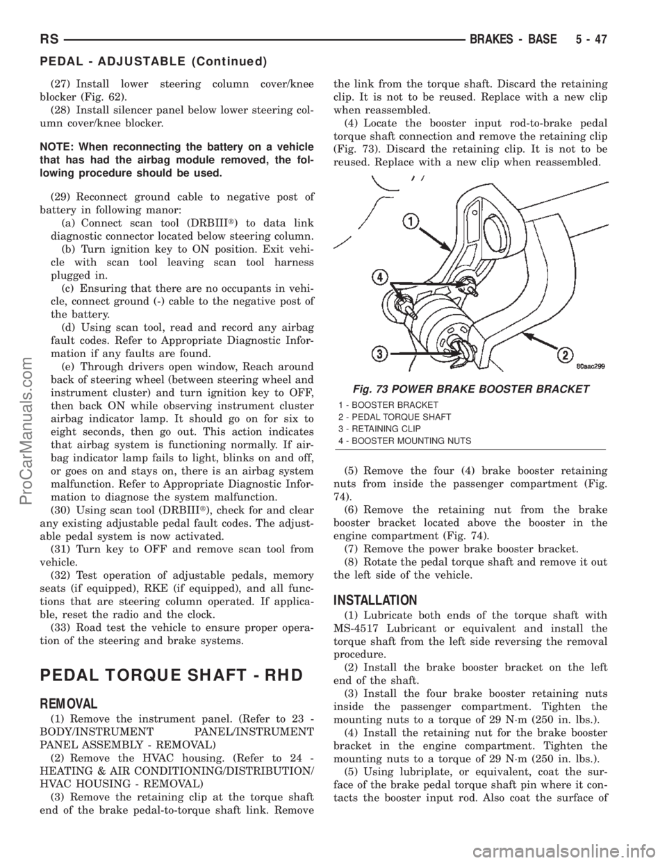
(4) Locate the booster input rod-to-brake pedal
torque shaft connection and remove the retaining clip
(Fig. 73). Discard the retaining clip. It is not to be
reused. Replace with a new clip when reassembled.
(5) Remove the four (4) brake booster retaining
nuts from inside the passenger compartment (Fig.
74).
(6) Remove the retaining nut from the brake
booster bracket located above the booster in the
engine compartment (Fig. 74).
(7) Remove the power brake booster bracket.
(8) Rotate the pedal torque shaft and remove it out
the left side of the vehicle.
INSTALLATION
(1) Lubricate both ends of the torque shaft with
MS-4517 Lubricant or equivalent and install the
torque shaft from the left side reversing the removal
procedure.
(2) Install the brake booster bracket on the left
end of the shaft.
(3) Install the four brake booster retaining nuts
inside the passenger compartment. Tighten the
mounting nuts to a torque of 29 N´m (250 in. lbs.).
(4) Install the retaining nut for the brake booster
bracket in the engine compartment. Tighten the
mounting nuts to a torque of 29 N´m (250 in. lbs.).
(5) Using lubriplate, or equivalent, coat the sur-
face of the brake pedal torque shaft pin where it con-
tacts the booster input rod. Also coat the surface of
Fig. 73 POWER BRAKE BOOSTER BRACKET
1 - BOOSTER BRACKET
2 - PEDAL TORQUE SHAFT
3 - RETAINING CLIP
4 - BOOSTER MOUNTING NUTS
RSBRAKES - BASE5-47
PEDAL - ADJUSTABLE (Continued)
ProCarManuals.com
Page 180 of 2399
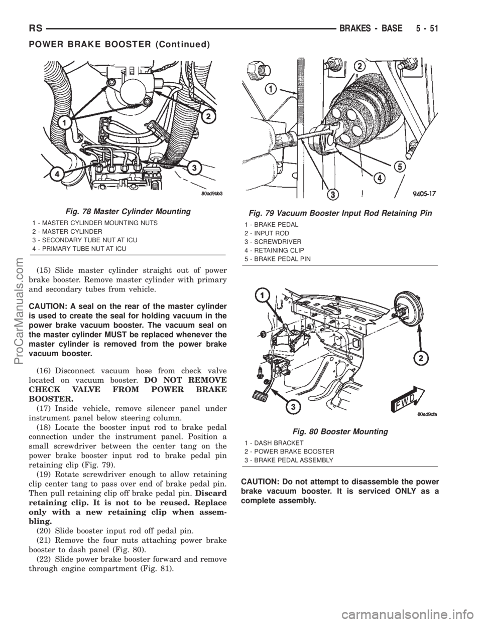
(15) Slide master cylinder straight out of power
brake booster. Remove master cylinder with primary
and secondary tubes from vehicle.
CAUTION: A seal on the rear of the master cylinder
is used to create the seal for holding vacuum in the
power brake vacuum booster. The vacuum seal on
the master cylinder MUST be replaced whenever the
master cylinder is removed from the power brake
vacuum booster.
(16) Disconnect vacuum hose from check valve
located on vacuum booster.DO NOT REMOVE
CHECK VALVE FROM POWER BRAKE
BOOSTER.
(17) Inside vehicle, remove silencer panel under
instrument panel below steering column.
(18) Locate the booster input rod to brake pedal
connection under the instrument panel. Position a
small screwdriver between the center tang on the
power brake booster input rod to brake pedal pin
retaining clip (Fig. 79).
(19) Rotate screwdriver enough to allow retaining
clip center tang to pass over end of brake pedal pin.
Then pull retaining clip off brake pedal pin.Discard
retaining clip. It is not to be reused. Replace
only with a new retaining clip when assem-
bling.
(20) Slide booster input rod off pedal pin.
(21) Remove the four nuts attaching power brake
booster to dash panel (Fig. 80).
(22) Slide power brake booster forward and remove
through engine compartment (Fig. 81).CAUTION: Do not attempt to disassemble the power
brake vacuum booster. It is serviced ONLY as a
complete assembly.
Fig. 78 Master Cylinder Mounting
1 - MASTER CYLINDER MOUNTING NUTS
2 - MASTER CYLINDER
3 - SECONDARY TUBE NUT AT ICU
4 - PRIMARY TUBE NUT AT ICU
Fig. 79 Vacuum Booster Input Rod Retaining Pin
1 - BRAKE PEDAL
2 - INPUT ROD
3 - SCREWDRIVER
4 - RETAINING CLIP
5 - BRAKE PEDAL PIN
Fig. 80 Booster Mounting
1 - DASH BRACKET
2 - POWER BRAKE BOOSTER
3 - BRAKE PEDAL ASSEMBLY
RSBRAKES - BASE5-51
POWER BRAKE BOOSTER (Continued)
ProCarManuals.com
Page 183 of 2399
(3) Using lubriplate, or equivalent, coat the sur-
face of the brake pedal pin where it contacts the
booster input rod.
CAUTION: When installing the brake pedal pin on
the power brake booster input rod, do not re-use
the old retaining clip.
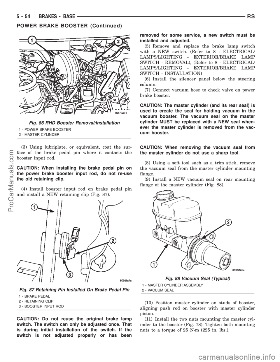
(4) Install booster input rod on brake pedal pin
and install a NEW retaining clip (Fig. 87).
CAUTION: Do not reuse the original brake lamp
switch. The switch can only be adjusted once. That
is during initial installation of the switch. If the
switch is not adjusted properly or has beenremoved for some service, a new switch must be
installed and adjusted.
(5) Remove and replace the brake lamp switch
with a NEW switch. (Refer to 8 - ELECTRICAL/
LAMPS/LIGHTING - EXTERIOR/BRAKE LAMP
SWITCH - REMOVAL), (Refer to 8 - ELECTRICAL/
LAMPS/LIGHTING - EXTERIOR/BRAKE LAMP
SWITCH - INSTALLATION)
(6) Install the silencer panel below the steering
column.
(7) Connect vacuum hose to check valve on power
brake booster.
CAUTION: The master cylinder (and its rear seal) is
used to create the seal for holding vacuum in the
vacuum booster. The vacuum seal on the master
cylinder MUST be replaced with a NEW seal when-
ever the master cylinder is removed from the vac-
uum booster.
CAUTION: When removing the vacuum seal from
the master cylinder do not use a sharp tool.
(8) Using a soft tool such as a trim stick, remove
the vacuum seal from the master cylinder mounting
flange.
(9) Install a NEW vacuum seal on rear mounting
flange of the master cylinder (Fig. 88).
(10) Position master cylinder on studs of booster,
aligning push rod on booster with master cylinder
piston.
(11) Install the two nuts mounting the master cyl-
inder to the booster (Fig. 78). Tighten both mounting
nuts to a torque of 25 N´m (225 in. lbs.).
Fig. 86 RHD Booster Removal/Installation
1 - POWER BRAKE BOOSTER
2 - MASTER CYLINDER
Fig. 87 Retaining Pin Installed On Brake Pedal Pin
1 - BRAKE PEDAL
2 - RETAINING CLIP
3 - BOOSTER INPUT ROD
Fig. 88 Vacuum Seal (Typical)
1 - MASTER CYLINDER ASSEMBLY
2 - VACUUM SEAL
5 - 54 BRAKES - BASERS
POWER BRAKE BOOSTER (Continued)
ProCarManuals.com
Page 189 of 2399

ROTOR RUNOUT
On-vehicle rotor runout is the combination of the
individual runout of the hub face and the runout of
the rotor. (The hub and rotor runouts are separable).
To measure rotor runout on the vehicle, first remove
the tire and wheel assembly. Reinstall the wheel
mounting nuts on the studs, tightening the rotor to
the hub. Mount the Dial Indicator, Special Tool
C-3339, with Mounting Adaptor, Special Tool SP-
1910 on steering arm. The dial indicator plunger
should contact braking surface of rotor approximately
ten millimeters from edge of rotor (Fig. 95). Check
lateral runout on both sides of the rotor, marking the
low and high spots on both. Runout limits can be
found in the specification table in this section. (Refer
to 5 - BRAKES/HYDRAULIC/MECHANICAL/RO-
TOR - SPECIFICATIONS)
If runout is in excess of the specification, check the
lateral runout of the hub face. Before removing the
rotor from the hub, place a chalk mark across both
the rotor and the one wheel stud closest to where the
high runout measurement was taken. This way, the
original mounting spot of the rotor on the hub is
indexed (Fig. 96).
Remove the rotor from the hub.
NOTE: Clean the hub face surface before checking
runout. This provides a clean surface to get an
accurate indicator reading.Mount Dial Indicator, Special Tool C-3339, and
Mounting Adaptor, Special Tool SP-1910, to the steer-
ing knuckle. Position the indicator stem so it contacts
the hub face near the outer diameter. Care must be
taken to position stem outside of the stud circle, but
inside of the chamfer on the hub rim (Fig. 97).
Hub runout should not exceed 0.03 mm (0.0012
inch). If runout exceeds this specification, the hub
must be replaced. (Refer to 2 - SUSPENSION/
FRONT/HUB / BEARING - REMOVAL)(Refer to 2 -
SUSPENSION/REAR/HUB / BEARING - REMOVAL)
Fig. 94 Checking Rotor For Thickness
1 - CALIPER
Fig. 95 Checking Rotor Runout
1 - SPECIAL TOOL SP-1910
2 - 10 MILLIMETERS FROM EDGE
3 - DISC SURFACE
4 - SPECIAL TOOL C-3339
Fig. 96 Marking Rotor and Wheel Stud
1 - CHALK MARK
5 - 60 BRAKES - BASERS
ROTOR (Continued)
ProCarManuals.com
Page 191 of 2399
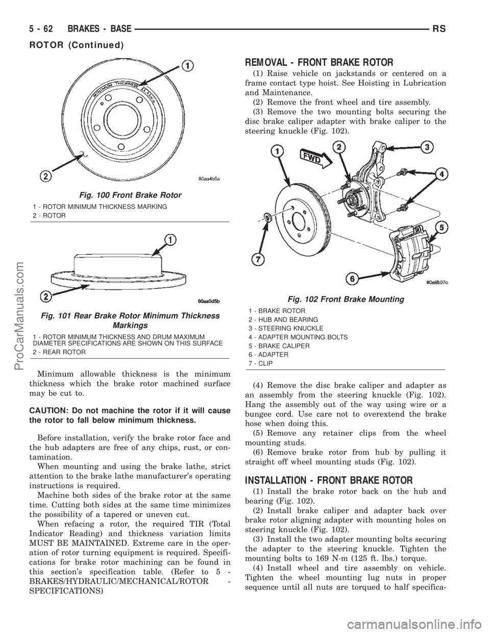
Minimum allowable thickness is the minimum
thickness which the brake rotor machined surface
may be cut to.
CAUTION: Do not machine the rotor if it will cause
the rotor to fall below minimum thickness.
Before installation, verify the brake rotor face and
the hub adapters are free of any chips, rust, or con-
tamination.
When mounting and using the brake lathe, strict
attention to the brake lathe manufacturer's operating
instructions is required.
Machine both sides of the brake rotor at the same
time. Cutting both sides at the same time minimizes
the possibility of a tapered or uneven cut.
When refacing a rotor, the required TIR (Total
Indicator Reading) and thickness variation limits
MUST BE MAINTAINED. Extreme care in the oper-
ation of rotor turning equipment is required. Specifi-
cations for brake rotor machining can be found in
this section's specification table. (Refer to 5 -
BRAKES/HYDRAULIC/MECHANICAL/ROTOR -
SPECIFICATIONS)
REMOVAL - FRONT BRAKE ROTOR
(1) Raise vehicle on jackstands or centered on a
frame contact type hoist. See Hoisting in Lubrication
and Maintenance.
(2) Remove the front wheel and tire assembly.
(3) Remove the two mounting bolts securing the
disc brake caliper adapter with brake caliper to the
steering knuckle (Fig. 102).
(4) Remove the disc brake caliper and adapter as
an assembly from the steering knuckle (Fig. 102).
Hang the assembly out of the way using wire or a
bungee cord. Use care not to overextend the brake
hose when doing this.
(5) Remove any retainer clips from the wheel
mounting studs.
(6) Remove brake rotor from hub by pulling it
straight off wheel mounting studs (Fig. 102).
INSTALLATION - FRONT BRAKE ROTOR
(1) Install the brake rotor back on the hub and
bearing (Fig. 102).
(2) Install brake caliper and adapter back over
brake rotor aligning adapter with mounting holes on
steering knuckle (Fig. 102).
(3) Install the two adapter mounting bolts securing
the adapter to the steering knuckle. Tighten the
mounting bolts to 169 N´m (125 ft. lbs.) torque.
(4) Install wheel and tire assembly on vehicle.
Tighten the wheel mounting lug nuts in proper
sequence until all nuts are torqued to half specifica-
Fig. 100 Front Brake Rotor
1 - ROTOR MINIMUM THICKNESS MARKING
2 - ROTOR
Fig. 101 Rear Brake Rotor Minimum Thickness
Markings
1 - ROTOR MINIMUM THICKNESS AND DRUM MAXIMUM
DIAMETER SPECIFICATIONS ARE SHOWN ON THIS SURFACE
2 - REAR ROTOR
Fig. 102 Front Brake Mounting
1 - BRAKE ROTOR
2 - HUB AND BEARING
3 - STEERING KNUCKLE
4 - ADAPTER MOUNTING BOLTS
5 - BRAKE CALIPER
6 - ADAPTER
7 - CLIP
5 - 62 BRAKES - BASERS
ROTOR (Continued)
ProCarManuals.com
Page 202 of 2399

(3) Remove sill scuff plate from left door sill.
(4) Remove the left side kick panel.
(5) Remove the silencer panel under the instru-
ment panel.
(6) Remove the steering column cover from the
lower instrument panel.
(7) Remove the reinforcement from the lower
instrument panel.
(8) Remove the front parking brake cable from the
parking brake cable equalizer (Fig. 121).
(9) Remove tension from front park brake cable.
Tension is removed by releasing the locking pliers
from the front park brake cable.
(10) Remove the 3 bolts mounting the wiring junc-
tion block to the instrument panel.
NOTE: When removing the lower mounting bolt,
push the park brake pedal down 5 clicks to access
the lower mounting bolt.
(11) Remove the lower bolt mounting the park
brake pedal to the body (Fig. 122).
(12) Remove the forward nut mounting the park
brake pedal to the body (Fig. 122).
(13) Remove the upper bolt mounting the park
brake pedal to the body (Fig. 122).
(14) Pull downward on front park brake cable
while rotating park brake pedal mechanism out from
behind junction block.
(15) Remove park brake pedal release link from
park brake mechanism.
(16) Remove the warning lamp ground switch con-
nector from the park brake pedal mechanism (Fig.
122).(17) Remove front park brake cable button from
park brake pedal mechanism. Tap end housing for
front park brake cable out of park brake pedal mech-
anism.
INSTALLATION
(1) Install park brake cable end housing into park
brake pedal mechanism.
(2) Install cable retainer onto the park brake cable
strand and then install retainer into pedal bracket.
(3) Install cable strand button into the clevis on
the park brake pedal mechanism.
(4) Install wiring harness connector on warning
indicator lamp ground switch.
(5) Install the park brake release rod on the
release mechanism of the park brake pedal.
(6) Position the park brake pedal mechanism into
its installed position on the body of the vehicle.
(7) Loosely install the top bolt mounting the park
brake pedal mechanism to the body (Fig. 122).
(8) Loosely install the forward nut mounting the
park brake pedal mechanism to the body (Fig. 122).
(9) Loosely install the lower bolt mounting the
park brake pedal mechanism to the body (Fig. 122).
(10) Tighten pedal mechanism attaching bolts and
nut to 28 N´m (250 in. lbs.).
(11) Verify that the park brake pedal is in the fully
released (full up) position.
(12) Raise vehicle.
(13) Install the front park brake cable on the park
brake cable equalizer (Fig. 121).
Fig. 121 Parking Brake Cable Equalizer
1 - EQUALIZER
2 - LEFT REAR PARKING BRAKE CABLE
3 - LOCKING NUT
4 - INTERMEDIATE PARKING BRAKE CABLE
5 - FRONT PARKING BRAKE CABLE
Fig. 122 PARKING BRAKE LEVER MOUNTING
1 - WIRE HARNESS CONNECTOR
2 - LEVER MECHANISM
3 - FRONT CABLE
RSBRAKES - BASE5-73
LEVER - PARKING BRAKE (Continued)
ProCarManuals.com
Page 203 of 2399
NOTE: If the original lever assembly is being used,
the lever mechanism auto adjuster spring tension
will need to be reset. (Refer to 5 - BRAKES/PARK-
ING BRAKE - STANDARD PROCEDURE)
(14) Lower vehicle.
(15) Remove the lock-out pin (if a new lever has
been installed) from the automatic cable adjuster on
the park brake pedal mechanism.
(16) Install the electrical junction block on the
instrument panel.
(17) Install the reinforcement on the lower instru-
ment panel.
(18) Install the steering column lower cover on the
lower instrument panel.
(19) Install the silencer panel under the instru-
ment panel.
(20) Install the left side kick panel.
(21) Install the sill scuff plate on the lower sill of
the left door.
(22) Install the negative (ground) cable on the bat-
tery.
(23) Cycle the park brake pedal one time. This will
seat the park brake cables and will allow the auto-
matic self adjuster to properly tension the park brake
cables.
LEVER - PARKING BRAKE
(EXPORT)
REMOVAL - PARKING BRAKE LEVER AND
FRONT CABLE
(1)Raise vehicle. (Refer to LUBRICATION & MAIN-
TENANCE/HOISTING - STANDARD PROCEDURE)
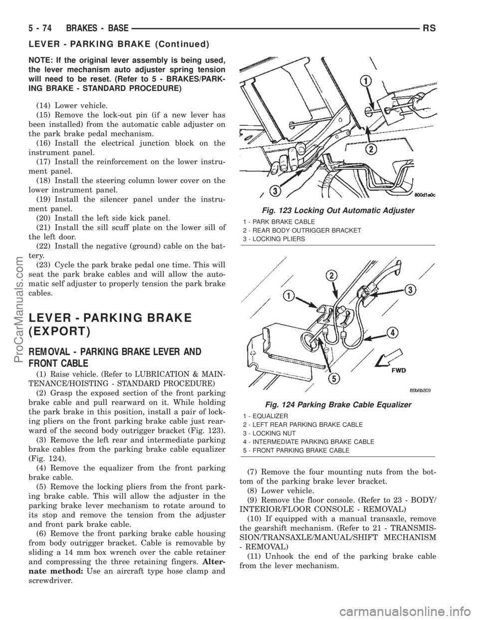
(2) Grasp the exposed section of the front parking
brake cable and pull rearward on it. While holding
the park brake in this position, install a pair of lock-
ing pliers on the front parking brake cable just rear-
ward of the second body outrigger bracket (Fig. 123).
(3) Remove the left rear and intermediate parking
brake cables from the parking brake cable equalizer
(Fig. 124).
(4) Remove the equalizer from the front parking
brake cable.
(5) Remove the locking pliers from the front park-
ing brake cable. This will allow the adjuster in the
parking brake lever mechanism to rotate around to
its stop and remove the tension from the adjuster
and front park brake cable.
(6) Remove the front parking brake cable housing
from body outrigger bracket. Cable is removable by
sliding a 14 mm box wrench over the cable retainer
and compressing the three retaining fingers.Alter-
nate method:Use an aircraft type hose clamp and
screwdriver.(7) Remove the four mounting nuts from the bot-
tom of the parking brake lever bracket.
(8) Lower vehicle.
(9) Remove the floor console. (Refer to 23 - BODY/
INTERIOR/FLOOR CONSOLE - REMOVAL)
(10) If equipped with a manual transaxle, remove
the gearshift mechanism. (Refer to 21 - TRANSMIS-
SION/TRANSAXLE/MANUAL/SHIFT MECHANISM
- REMOVAL)
(11) Unhook the end of the parking brake cable
from the lever mechanism.
Fig. 123 Locking Out Automatic Adjuster
1 - PARK BRAKE CABLE
2 - REAR BODY OUTRIGGER BRACKET
3 - LOCKING PLIERS
Fig. 124 Parking Brake Cable Equalizer
1 - EQUALIZER
2 - LEFT REAR PARKING BRAKE CABLE
3 - LOCKING NUT
4 - INTERMEDIATE PARKING BRAKE CABLE
5 - FRONT PARKING BRAKE CABLE
5 - 74 BRAKES - BASERS
LEVER - PARKING BRAKE (Continued)
ProCarManuals.com
Page 214 of 2399

BRAKES - ABS
TABLE OF CONTENTS
page page
BRAKES - ABS
DESCRIPTION
DESCRIPTION - ANTILOCK BRAKE
SYSTEM............................85
DESCRIPTION - ANTILOCK BRAKE
SYSTEM (EXPORT)....................85
DESCRIPTION - ELECTRONIC VARIABLE
BRAKE PROPORTIONING...............86
DESCRIPTION - TRACTION CONTROL
SYSTEM............................86
OPERATION
OPERATION - ANTILOCK BRAKE SYSTEM . . 86
OPERATION - ELECTRONIC VARIABLE
BRAKE PROPORTIONING...............87
OPERATION - TRACTION CONTROL
SYSTEM............................87
CAUTION
CAUTIONS..........................88
STANDARD PROCEDURE - ANTILOCK BRAKE
SYSTEM BLEEDING...................88
SPECIFICATIONS
ABS FASTENER TORQUE...............89
TONE WHEEL RUNOUT................89
WHEEL SPEED SENSOR AIR GAP........89
FRONT WHEEL SPEED SENSOR
REMOVAL.............................89
INSTALLATION.........................89
REAR WHEEL SPEED SENSOR - AWD
REMOVAL.............................90INSTALLATION.........................90
REAR WHEEL SPEED SENSOR - FWD
REMOVAL.............................91
INSTALLATION.........................91
TONE WHEEL
INSPECTION - TONE WHEEL..............92
TRACTION CONTROL SWITCH
DIAGNOSIS AND TESTING - TRACTION
CONTROL SWITCH....................92
HYDRAULIC/MECHANICAL
OPERATION - HYDRAULIC CIRCUITS AND
VALVES .............................93
HCU (HYDRAULIC CONTROL UNIT)
DESCRIPTION.........................99
OPERATION...........................99
ICU (INTEGRATED CONTROL UNIT)
DESCRIPTION........................100
OPERATION..........................100
REMOVAL
REMOVAL - LHD.....................100
REMOVAL - RHD.....................101
DISASSEMBLY - ICU...................103
ASSEMBLY - ICU......................103
INSTALLATION
INSTALLATION - LHD.................104
INSTALLATION - RHD.................105
BRAKES - ABS
DESCRIPTION
DESCRIPTION - ANTILOCK BRAKE SYSTEM
This section covers the physical and operational
descriptions and the on-car service procedures for the
Mark 20e Antilock Brake System and the Mark 20e
Antilock Brake System with traction control.
The purpose of the antilock brake system (ABS) is
to prevent wheel lockup under braking conditions on
virtually any type of road surface. Antilock braking is
desirable because a vehicle that is stopped without
locking the wheels retains directional stability and
some steering capability. This allows the driver to
retain greater control of the vehicle during braking.
DESCRIPTION - ANTILOCK BRAKE SYSTEM
(EXPORT)
Four-wheel disc antilock brakes are standard on all
models. The Mark 20e antilock brake system is used
on all models. Depending on whether the vehicle is a
left-hand drive (LHD) or right-hand drive (RHD)
model, the integrated control unit (ICU) is located in
one of two locations. On LHD models, the ICU is
mounted above the front suspension cradle/cross-
member below the master cylinder. On RHD models,
the ICU is located behind the front suspension cra-
dle/crossmember on the left side of the vehicle.
RSBRAKES - ABS5-85
ProCarManuals.com
Page 215 of 2399

DESCRIPTION - ELECTRONIC VARIABLE
BRAKE PROPORTIONING
Vehicles equipped with ABS use electronic variable
brake proportioning (EVBP) to balance front-to-rear
braking. The EVBP is used in place of a rear propor-
tioning valve. The EVBP system uses the ABS sys-
tem to control the slip of the rear wheels in partial
braking range. The braking force of the rear wheels
is controlled electronically by using the inlet and out-
let valves located in the integrated control unit
(ICU).
DESCRIPTION - TRACTION CONTROL SYSTEM
Traction control reduces wheel slip and maintains
traction at the driving wheels at speeds below 56
km/h (35 mph) when road surfaces are slippery. The
traction control system reduces wheel slip by braking
the wheel that is losing traction.
HYDRAULIC SHUTTLE VALVES
Two pressure relief hydraulic shuttle valves are
included on vehicles with traction control. These
valves are located inside the HCU and cannot be ser-
viced separately from the HCU.
TRACTION CONTROL LAMP
The traction control function lamp is located in the
transmission range indicator display of the instru-
ment cluster, displaying TRAC, TRAC OFF or nei-
ther depending on system mode.
The TRAC OFF lamp is controlled by a Traction
Control Off switch that is a momentary contact type
switch. The Traction Control Off switch is located on
the steering column upper shroud.
OPERATION
OPERATION - ANTILOCK BRAKE SYSTEM
There are a few performance characteristics of the
Mark 20e Antilock Brake System that may at first
seem abnormal, but in fact are normal. These char-
acteristics are described below.
NORMAL BRAKING
Under normal braking conditions, the ABS func-
tions the same as a standard base brake system with
a diagonally split master cylinder and conventional
vacuum assist.
ABS BRAKING
ABS operation is available at all vehicle speeds
above 3±5 mph. If a wheel locking tendency is
detected during a brake application, the brake sys-
tem enters the ABS mode. During ABS braking,
hydraulic pressure in the four wheel circuits is mod-ulated to prevent any wheel from locking. Each
wheel circuit is designed with a set of electric sole-
noids to allow modulation, although for vehicle sta-
bility, both rear wheel solenoids receive the same
electrical signal. Wheel lockup may be perceived at
the very end of an ABS stop and is considered nor-
mal.
During an ABS stop, the brakes hydraulic system
is still diagonally split. However, the brake system
pressure is further split into three control channels.
During antilock operation of the vehicle's brake sys-
tem, the front wheels are controlled independently
and are on two separate control channels, and the
rear wheels of the vehicle are controlled together.
The system can build and release pressure at each
wheel, depending on signals generated by the wheel
speed sensors (WSS) at each wheel and received at
the controller antilock brake (CAB).
NOISE AND BRAKE PEDAL FEEL
During ABS braking, some brake pedal movement
may be felt. In addition, ABS braking will create
ticking, popping, or groaning noises heard by the
driver. This is normal and is due to pressurized fluid
being transferred between the master cylinder and
the brakes. If ABS operation occurs during hard
braking, some pulsation may be felt in the vehicle
body due to fore and aft movement of the suspension
as brake pressures are modulated.
At the end of an ABS stop, ABS is turned off when
the vehicle is slowed to a speed of 3±4 mph. There
may be a slight brake pedal drop anytime that the
ABS is deactivated, such as at the end of the stop
when the vehicle speed is less than 3 mph or during
an ABS stop where ABS is no longer required. These
conditions exist when a vehicle is being stopped on a
road surface with patches of ice, loose gravel, or sand
on it. Also, stopping a vehicle on a bumpy road sur-
face activates ABS because of the wheel hop caused
by the bumps.
TIRE NOISE AND MARKS
Although the ABS system prevents complete wheel
lockup, some wheel slip is desired in order to achieve
optimum braking performance. Wheel slip is defined
as follows: 0 percent slip means the wheel is rolling
freely and 100 percent slip means the wheel is fully
locked. During brake pressure modulation, wheel slip
is allowed to reach up to 25±30 percent. This means
that the wheel rolling velocity is 25±30 percent less
than that of a free rolling wheel at a given vehicle
speed. This slip may result in some tire chirping,
depending on the road surface. This sound should not
be interpreted as total wheel lockup.
Complete wheel lockup normally leaves black tire
marks on dry pavement. The ABS will not leave dark
5 - 86 BRAKES - ABSRS
BRAKES - ABS (Continued)
ProCarManuals.com