steering CHRYSLER VOYAGER 2002 Repair Manual
[x] Cancel search | Manufacturer: CHRYSLER, Model Year: 2002, Model line: VOYAGER, Model: CHRYSLER VOYAGER 2002Pages: 2399, PDF Size: 57.96 MB
Page 216 of 2399
black tire marks since the wheel never reaches a
fully locked condition. However, tire marks may be
noticeable as light patched marks.
START-UP CYCLE
When the ignition is turned on, a popping sound
and a slight brake pedal movement may be noticed.
The ABS warning lamp will also be on for up to 5
seconds after the ignition is turned on. When the
vehicle is first driven off, a humming may be heard
or felt by the driver at approximately 20±40 kph
(12±25 mph). All of these conditions are a normal
function of ABS as the system is performing a diag-
nosis check.
PREMATURE ABS CYCLING
Symptoms of premature ABS cycling include: click-
ing sounds from the solenoid valves; pump/motor
running; and pulsations in the brake pedal. Prema-
ture ABS cycling can occur at any braking rate of the
vehicle and on any type of road surface. Neither the
red BRAKE warning lamp, nor the amber ABS warn-
ing lamp, illuminate and no fault codes are stored in
the CAB.
Premature ABS cycling is a condition that needs to
be correctly assessed when diagnosing problems with
the antilock brake system. It may be necessary to use
a DRB scan tool to detect and verify premature ABS
cycling.
Check the following common causes when diagnos-
ing premature ABS cycling: damaged tone wheels;
incorrect tone wheels; damaged steering knuckle
wheel speed sensor mounting bosses; loose wheel
speed sensor mounting bolts; excessive tone wheel
runout; or an excessively large tone wheel-to-wheel
speed sensor air gap. Give special attention to these
components when diagnosing a vehicle exhibiting
premature ABS cycling.
After diagnosing the defective component, repair or
replace it as required. When the component repair or
replacement is completed, test drive the vehicle to
verify that premature ABS cycling has been cor-
rected.
OPERATION - ELECTRONIC VARIABLE BRAKE
PROPORTIONING
Upon entry into EVBP the inlet valve for the rear
brake circuit is switched on so that the fluid supply
from the master cylinder is shut off. In order to
decrease the rear brake pressure, the outlet valve for
the rear brake circuit is pulsed. This allows fluid to
enter the low pressure accumulator (LPA) in the
hydraulic control unit (HCU) resulting in a drop in
fluid pressure to the rear brakes. In order to increase
the rear brake pressure, the outlet valve is switched
off and the inlet valve is pulsed. This increases thepressure to the rear brakes. This back-and-forth pro-
cess will continue until the required slip difference is
obtained. At the end of EVBP braking (brakes
released) the fluid in the LPA drains back to the
master cylinder by switching on the outlet valve and
draining through the inlet valve check valve. At the
same time the inlet valve is switched on in case of
another brake application.
The EVBP will remain functional during many
ABS fault modes. If both the red BRAKE and amber
ABS warning indicators are illuminated, the EVBP
may not be functioning.
OPERATION - TRACTION CONTROL SYSTEM
The traction control module monitors wheel speed.
During acceleration, if the module detects front
(drive) wheel slip and the brakes are not applied, the
module enters traction control mode. Traction control
operation proceeds in the following order:
(1) Close the normally open isolation valves.
(2) Start the pump/motor and supply volume and
pressure to the front (drive) hydraulic circuit. (The
pump/motor runs continuously during traction con-
trol operation.)
(3) Open and close the build and decay valves to
maintain minimum wheel slip and maximum trac-
tion.
The cycling of the build and decay valves during
traction control is similar to that during antilock
braking, except the valves work to control wheel spin
by applying the brakes, whereas the ABS function is
to control wheel skid by releasing the brakes.
If the brakes are applied at anytime during a trac-
tion control cycle, the brake lamp switch triggers the
controller to switch off traction control.
HYDRAULIC SHUTTLE VALVES
Two pressure relief hydraulic shuttle valves allow
pressure and volume to return to the master cylinder
reservoir when not consumed by the build and decay
valves. These valves are necessary because the
pump/motor supplies more volume than the system
requires.
TRACTION CONTROL LAMP
The traction control system is enabled at each igni-
tion cycle. It may be turned off by depressing the
Traction Control Off switch button when the ignition
is in the ON position. The traction control function
lamp (TRAC OFF) illuminates immediately upon
depressing the button.
The traction control function lamp illuminates dur-
ing a traction control cycle, displaying TRAC.
If the CAB calculates that the brake temperatures
are high, the traction control system becomes inoper-
ative until a time-out period has elapsed. During this
RSBRAKES - ABS5-87
BRAKES - ABS (Continued)
ProCarManuals.com
Page 218 of 2399
The ABS portion of the brake system must be bled
separately. Use the following procedure to properly
bleed the brake hydraulic system including the ABS.
BLEEDING
When bleeding the ABS system, the following
bleeding sequence must be followed to insure com-
plete and adequate bleeding.
(1) Make sure all hydraulic fluid lines are installed
and properly torqued.
(2) Connect the DRBIIItscan tool to the diagnos-
tics connector. The diagnostic connector is located
under the lower steering column cover to the left of
the steering column.
(3) Using the DRB, check to make sure the CAB
does not have any fault codes stored. If it does, clear
them using the DRB.
WARNING: WHEN BLEEDING THE BRAKE SYSTEM
WEAR SAFETY GLASSES. A CLEAR BLEED TUBE
MUST BE ATTACHED TO THE BLEEDER SCREWS
AND SUBMERGED IN A CLEAR CONTAINER FILLED
PART WAY WITH CLEAN BRAKE FLUID. DIRECT
THE FLOW OF BRAKE FLUID AWAY FROM YOUR-
SELF AND THE PAINTED SURFACES OF THE VEHI-
CLE. BRAKE FLUID AT HIGH PRESSURE MAY
COME OUT OF THE BLEEDER SCREWS WHEN
OPENED.
(4) Bleed the base brake system using the stan-
dard pressure or manual bleeding procedure. (Refer
to 5 - BRAKES - BASE - STANDARD PROCEDURE)
(5) Using the DRB, select ANTILOCK BRAKES,
followed by MISCELLANEOUS, then BLEED
BRAKES. Follow the instructions displayed. When
the scan tool displays TEST COMPLETED, discon-
nect the scan tool and proceed.
(6) Bleed the base brake system a second time.
Check brake fluid level in the reservoir periodically
to prevent emptying, causing air to enter the hydrau-
lic system.
(7) Fill the master cylinder reservoir to the full
level.
(8) Test drive the vehicle to be sure the brakes are
operating correctly and that the brake pedal does not
feel spongy.
SPECIFICATIONS
ABS FASTENER TORQUE
(Refer to 5 - BRAKES - BASE - SPECIFICA-
TIONS)
TONE WHEEL RUNOUT
DESCRIPTION SPECIFICATION
Front Tone Wheel
Maximum Runout0.15 mm (0.006 in.)
Rear Tone Wheel
Maximum Runout0.15 mm (0.006 in.)
WHEEL SPEED SENSOR AIR GAP
DESCRIPTION SPECIFICATION
Front Sensor0.35 ± 1.20 mm
0.014 ± 0.047 in.
Rear Sensor0.40 ± 1.20 mm
0.016 ± 0.047 in.
FRONT WHEEL SPEED
SENSOR
REMOVAL
(1) Raise vehicle. (Refer to LUBRICATION &
MAINTENANCE/HOISTING - STANDARD PROCE-
DURE)
(2) Remove the tire and wheel assembly.
(3) Remove the sensor cable routing clamp screws.
CAUTION: When disconnecting the wheel speed
sensor from vehicle wiring harness, be careful not
to damage pins on connector
(4) Remove speed sensor cable grommets from
intermediate bracket on strut.
(5) Disconnect speed sensor cable from vehicle wir-
ing harness behind fender well shield.
(6) Remove the wheel speed sensor head mounting
bolt (Fig. 1).
(7) Remove sensor head from steering knuckle. If
sensor has seized due to corrosion,DO NOT USE
PLIERS ON SENSOR HEAD.Use a hammer and a
punch and tap edge of sensor ear, rocking the sensor
side-to-side until free.
(8) Remove front wheel speed sensor from vehicle.
INSTALLATION
CAUTION: Proper installation of wheel speed sen-
sor cables is critical to continued system operation.
Be sure that cables are installed in retainers. Fail-
ure to install cables in retainers as shown in this
section may result in contact with moving parts and
over extension of cables, resulting in an open cir-
cuit.
RSBRAKES - ABS5-89
BRAKES - ABS (Continued)
ProCarManuals.com
Page 219 of 2399

(1) Connect the front wheel speed sensor cable to
the vehicle wiring harness connector. Be sure speed
sensor cable connector is fully seated and locked into
vehicle wiring harness connector.
(2) Install the bolts attaching the routing clamps
to the body of the vehicle. Tighten the bolts to a
torque of 14 N´m (125 in. lbs.).
(3) Insert speed sensor cable grommets into inter-
mediate bracket on strut.
(4) Install the wheel speed sensor head mounting
bolt (Fig. 1). Tighten the bolt to a torque of 13 N´m
(115 in. lbs.)
(5) Install the wheel and tire assembly on vehicle.
(6) Lower vehicle.
(7) Road test vehicle to ensure proper operation of
the base and ABS brake systems.
REAR WHEEL SPEED SENSOR
-AWD
REMOVAL
(1) Raise vehicle. (Refer to LUBRICATION &
MAINTENANCE/HOISTING - STANDARD PROCE-
DURE)
CAUTION: When disconnecting speed sensor cable
from vehicle wiring harness be careful not to dam-
age pins on the electrical connectors. Also, inspect
connectors for any signs of previous damage.(2) Remove grommet from floor pan of vehicle and
disconnect speed sensor cable connector from vehicle
wiring harness.
CAUTION: When removing rear wheel speed sensor
cable from routing clips, be sure not to damage the
routing clips. Routing clips that are molded onto
the brake hose will require replacement of the brake
hose if damaged during removal or installation of
the speed sensor cable.
(3) Carefully remove speed sensor cable from
press-in routing clips along brake hose and tubing.
(4) Remove bolt securing wheel speed sensor cable
metal clip to rear of axle. Remove metal clip from
cable if necessary.
CAUTION: If speed sensor head has seized due to
corrosion, do not use pliers on speed sensor head
in an attempt to remove it. Use a hammer and a
punch and tap mounting flange edge side-to-side,
rocking the sensor until free.
(5) Remove wheel speed sensor head attaching
bolt.
(6) Remove wheel speed sensor head from the axle,
and remove sensor from vehicle.
INSTALLATION
CAUTION: Proper installation of wheel speed sen-
sor cables is critical to continued system operation.
Be sure that cables are installed in retainers. Fail-
ure to install cables in retainers as indicated may
result in contact with moving parts or over-exten-
sion of cables, resulting in an open circuit.
(1) Install wheel speed sensor head in axle flange.
CAUTION: Prior to installing the speed sensor head
attaching bolt, the plastic anti-rotation pin must be
fully seated into the bearing flange.
(2) Install wheel speed sensor head attaching bolt.
Tighten bolt to a torque 10 N´m (90 in. lbs.).
(3) Check the air gap between the face of the
wheel speed sensor and the top surface of the tone
wheel. (Refer to 5 - BRAKES - SPECIFICATIONS)
CAUTION: When installing wheel speed sensor
cable in the routing clips on rear brake flex hose,
be sure not to damage the routing clips. Routing
clips are molded onto the hose and will require
replacement of the brake hose if damaged.
(4) Install speed sensor cable under leaf spring
onto brake hose and tubing utilizing routing clips to
secure it in place.
Fig. 1 Front Wheel Speed Sensor Attaching Bolt
1 - MOUNTING BOLT
2 - WHEEL SPEED SENSOR
3 - DRIVESHAFT
4 - TONE WHEEL
5 - STEERING KNUCKLE
5 - 90 BRAKES - ABSRS
FRONT WHEEL SPEED SENSOR (Continued)
ProCarManuals.com
Page 230 of 2399

(7) Using a brake pedal depressor, move and lock
the brake pedal to a position past the first inch of
pedal travel.This will prevent brake fluid from
draining out of the master cylinder once the
brake tubes are removed from the HCU.
CAUTION: Do not apply a 12±volt power source to
any terminals of the 24-way CAB connector when
disconnected.
(8) Disconnect the wiring harness connector from
the speed control servo.
(9) Remove the speed control servo mounting nuts
and move the servo out of the way.
(10) Disconnect the 24±way connector from the
CAB. To disconnect the 24±way connector, grasp the
lock on the 24±way connector and pull it as far up as
possible. This will unlock the 24±way connector from
the socket on the CAB.
CAUTION: Before removing the brake tubes from
the HCU, the HCU must be thoroughly cleaned. This
must be done to prevent dirt particles from falling
into the ports of HCU or entering the brake tubes.
(11) Thoroughly clean all surfaces of the ICU and
brake tube nuts. Use only a solvent such as Mopart
Brake Parts Cleaner or equivalent to clean the ICU.
(12) Remove the brake tubes (4) from the outlet
ports on the HCU (Fig. 14).
(13) Remove the primary and secondary brake
tubes from the inlet ports on the HCU (Fig. 14).
(14) Center and prop the steering wheel.
(15) Remove the silencer panel under the instru-
ment panel, below the steering column.(16) Remove the pinch bolt and disconnect the
steering shaft coupling.
(17) Remove the two clips securing silencer to dash
seal (Fig. 15).
(18) Remove the three screws securing the dash
seal (Fig. 15).
(19) Remove the 3 bolts attaching the ICU to its
mounting bracket (Fig. 16).
(20) Remove ICU from the vehicle through engine
compartment.
(21) If required, to separating the CAB from the
HCU, (Refer to 5 - BRAKES - ABS/HYDRAULIC/ME-
CHANICAL/ICU (INTEGRATED CONTROL UNIT) -
DISASSEMBLY).
REMOVAL - RHD
NOTE: Before proceeding, (Refer to 5 - BRAKES -
WARNING)(Refer to 5 - BRAKES - CAUTION)
(1) Disconnect the negative (ground) cable from
the battery and isolate cable.
(2) Using a brake pedal depressor, move and lock
the brake pedal to a position past the first inch of
pedal travel.This will prevent brake fluid from
Fig. 14 BRAKE TUBE NUTS AT ICU
1 - PRIMARY BRAKE TUBE
2 - SECONDARY BRAKE TUBE
3 - CHASSIS BRAKE TUBES
Fig. 15 LOWER COUPLING AND DASH SEAL
1 - COUPLING
2 - DASH SEAL
3 - SILENCER
4 - MOUNTING SCREWS
5 - RETAINING CLIPS
6 - DASH
RSBRAKES - ABS5 - 101
ICU (INTEGRATED CONTROL UNIT) (Continued)
ProCarManuals.com
Page 233 of 2399
INSTALLATION
INSTALLATION - LHD
(1) Place the ICU in its bracket below the master
cylinder. Start the upper mounting bolt to hold it in
place.
(2) Inside the vehicle, install the remaining 2
mounting bolts attaching the ICU to the mounting
bracket (Fig. 16). Tighten all 3 mounting bolts to a
torque of 11 N´m (97 in. lbs.).
(3) Install the dash seal and three mounting
screws (Fig. 15).(4) Install the silencer on top of the dash seal (Fig.
15).
(5) Connect the steering shaft coupling and install
the pinch bolt (Fig. 15). Tighten the pinch bolt to 28
N´m (250 in. lbs.).
(6) Install the silencer panel below the steering
column under the instrument panel.
(7) Remove the steering wheel holder.
CAUTION: Because of the flexible section in the pri-
mary and secondary brake tubes, the brake tubes
must be held in proper orientation when tightened
and torqued. These tubes must not contact each
other or other vehicle components when installed.
Also, after the brake tubes are installed on the HCU,
ensure all spacer clips are reinstalled on the brake
tubes.
(8) Install the primary and secondary brake tubes
into their correct port locations on the HCU valve
block (Fig. 14). Tighten the tube nuts to a torque of
17 N´m (145 in. lbs.).
CAUTION: When installing the chassis brake tubes
on the HCU valve block, they must be located cor-
rectly in the valve block to ensure proper ABS oper-
ation.
NOTE: The chassis brake tube attachment locations
to the HCU, are marked on the bottom of the CAB.
(9) Install the (4) chassis brake tubes into their
correct port locations on the HCU valve block as
shown (Fig. 14). Tighten the tube nuts to a torque of
17 N´m (145 in. lbs.).
Fig. 22 INTEGRATED CONTROL UNIT (ICU)
1 - PUMP/MOTOR
2 - HCU
3 - PUMP/MOTOR CONNECTOR
4 - CAB
Fig. 23 (TYPICAL) CAB Attaching Bolts
1 - MOUNTING BOLTS
2 - CAB
3 - HCU VALVE BLOCK
Fig. 24 (TYPICAL) Remove/Install CAB
1 - CAB
2 - HCU VALVES
3 - HCU VALVE BLOCK
5 - 104 BRAKES - ABSRS
ICU (INTEGRATED CONTROL UNIT) (Continued)
ProCarManuals.com
Page 255 of 2399
SPECIFICATIONS
COOLING SYSTEM CAPACITY
Engine Coolant Capacity*
2.4L 10.7 L (11.4 qts.)
3.3/3.8L (without
rear heater)12.6 L (13.4 qts.)
3.3/3.8L (with rear
heater)15.4 L (16.3 qts.)
*Includes Heater and Coolant Recovery System
ACCESSORY DRIVE BELT TENSION
ACCESSORY
DRIVE BELTTENSION
2.4L ENGINE
Air Conditioning
Compressor/
GeneratorDynamic Tensioner
Power
SteeringNew
Belt534 - 756 N
183 - 218 Hz
(120 - 170
lbs.)
Used
Belt*356 - 534 N
150 - 183 Hz
(80 - 120 lbs)
*Belt is considered used after 15 minutes of run-in
time
3.3/3.8L ENGINES
Air Conditioning
CompressorDynamic
Tensioner
Generator/Water
Pump/Power
Steering
TORQUE
DESCRIPTION N´mFt.
Lbs.In.
Lbs.
Accessory Drive Belt Tensioner
Assembly (3.3/3.8L)ÐBolt28 Ð 250
Engine Coolant Temperature
Sensor
(2.4 & 3.3/3.8L) 7 Ð 60
Generator & A/C Compressor Drive
Belt Tensioner Assembly (2.4L)Ð
Bolt54 40 Ð
Coolant Outlet Connector/
Thermostat Housing
(2.4 & 3.3/3.8L)ÐBolts 28 Ð 250
Water Pump
(2.4 & 3.3/3.8L)ÐBolts 12 Ð 105
Water Pump Inlet Tube (2.4L)Ð
Bolts12 Ð 105
Water Pump Inlet Tube (3.3/3.8L)Ð
Bolts28 Ð 250
Water Pump Pulley (3.3/3.8L)Ð
Bolts28 Ð 250
Radiator to A/C CondenserÐ
Screws5Ð45
Radiator FanÐScrews 5 Ð 45
Radiator Mounting (Upper
Bracket)ÐNuts12 Ð 105
7 - 6 COOLINGRS
COOLING (Continued)
ProCarManuals.com
Page 257 of 2399
ACCESSORY DRIVE
TABLE OF CONTENTS
page page
BELT TENSIONER - 2.4L
REMOVAL.............................8
INSTALLATION..........................8
BELT TENSIONER - 3.3/3.8L
REMOVAL.............................8
INSTALLATION..........................8
DRIVE BELTS
DESCRIPTION..........................9
OPERATION............................9
DIAGNOSIS AND TESTING - ACCESSORY
DRIVE BELT..........................9
DRIVE BELTS - 2.4L
STANDARD PROCEDURE - CHECKING
POWER STEERING BELT TENSION.......10REMOVAL.............................10
CLEANING............................11
INSPECTION..........................11
INSTALLATION.........................11
ADJUSTMENTS........................12
DRIVE BELTS - 3.3/3.8L
REMOVAL.............................12
CLEANING............................13
INSPECTION..........................13
INSTALLATION.........................13
BELT TENSIONER - 2.4L
REMOVAL
(1) Raise vehicle on hoist.
(2) Remove the drive belt shield.
(3) Remove the generator/A/C drive belt. (Refer to
7 - COOLING/ACCESSORY DRIVE/DRIVE BELTS -
REMOVAL)
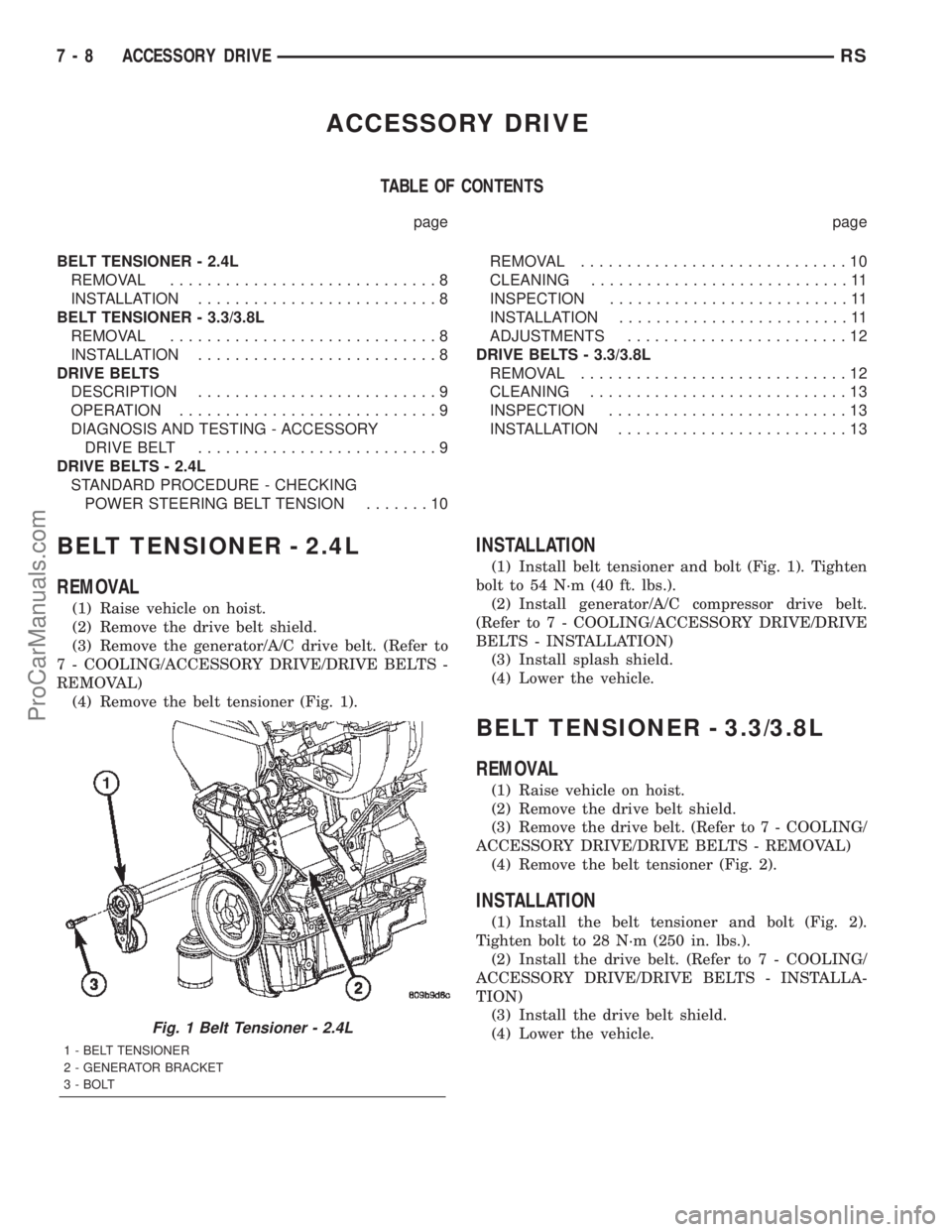
(4) Remove the belt tensioner (Fig. 1).
INSTALLATION
(1) Install belt tensioner and bolt (Fig. 1). Tighten
bolt to 54 N´m (40 ft. lbs.).
(2) Install generator/A/C compressor drive belt.
(Refer to 7 - COOLING/ACCESSORY DRIVE/DRIVE
BELTS - INSTALLATION)
(3) Install splash shield.
(4) Lower the vehicle.
BELT TENSIONER - 3.3/3.8L
REMOVAL
(1) Raise vehicle on hoist.
(2) Remove the drive belt shield.
(3) Remove the drive belt. (Refer to 7 - COOLING/
ACCESSORY DRIVE/DRIVE BELTS - REMOVAL)
(4) Remove the belt tensioner (Fig. 2).
INSTALLATION
(1) Install the belt tensioner and bolt (Fig. 2).
Tighten bolt to 28 N´m (250 in. lbs.).
(2) Install the drive belt. (Refer to 7 - COOLING/
ACCESSORY DRIVE/DRIVE BELTS - INSTALLA-
TION)
(3) Install the drive belt shield.
(4) Lower the vehicle.
Fig. 1 Belt Tensioner - 2.4L
1 - BELT TENSIONER
2 - GENERATOR BRACKET
3 - BOLT
7 - 8 ACCESSORY DRIVERS
ProCarManuals.com
Page 258 of 2399

DRIVE BELTS
DESCRIPTION
The drive belts are a Poly-V type belt. Belt widths
vary depending on the various engine and accessory
packages. Satisfactory performance of these belts
depends on belt condition and proper belt tension.
OPERATION
The accessory drive belts form the link between
the engine crankshaft and the engine driven accesso-
ries.
DIAGNOSIS AND TESTING - ACCESSORY DRIVE BELT
CONDITION POSSIBLE CAUSES CORRECTIONS
INSUFFICIENT ACCESSORY
OUTPUT DUE TO BELT SLIPPAGE1. Belt too loose 1. (a) Replace belt (auto-tensioned
belts)
(b) Adjust power steering belt
tension (4 cyl. engine)
2. Belt excessively glazed or worn 2. Replace and tighten as specified
BELT SQUEAL WHEN
ACCELERATING ENGINE1. Belts too loose 1. (a) Replace belt (auto-tensioned
belts)
(b) Adjust power steering belt
tension (4 cyl. engine)
2. Belt glazed 2. Replace belts
BELT SQUEAK AT IDLE 1. Belts too loose 1. (a) Replace belt (auto-tensioned
belts)
(b) Adjust power steering belt
tension (4 cyl. engine)
2. Dirt or paint imbedded in belt 2. Replace belt
3. Non-uniform belt 3. Replace belt
4. Misaligned pulleys 4. Align accessories
5. Non-uniform groove or eccentric
pulley5. Replace pulley
Fig. 2 BELT TENSIONER - 3.3/3.8L
1 - BELT TENSIONER
2 - BOLT
RSACCESSORY DRIVE7-9
BELT TENSIONER - 3.3/3.8L (Continued)
ProCarManuals.com
Page 259 of 2399
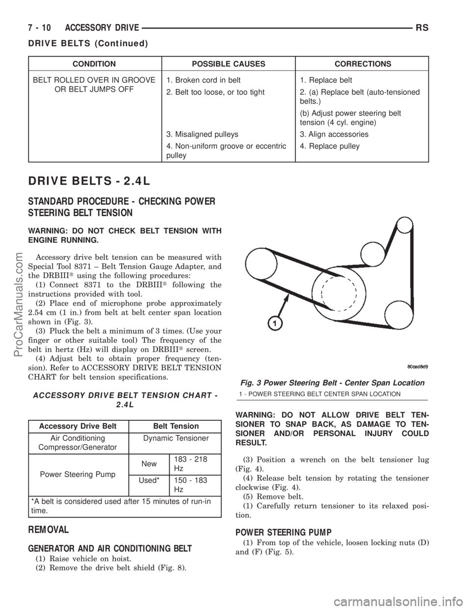
CONDITION POSSIBLE CAUSES CORRECTIONS
BELT ROLLED OVER IN GROOVE
OR BELT JUMPS OFF1. Broken cord in belt 1. Replace belt
2. Belt too loose, or too tight 2. (a) Replace belt (auto-tensioned
belts.)
(b) Adjust power steering belt
tension (4 cyl. engine)
3. Misaligned pulleys 3. Align accessories
4. Non-uniform groove or eccentric
pulley4. Replace pulley
DRIVE BELTS - 2.4L
STANDARD PROCEDURE - CHECKING POWER
STEERING BELT TENSION
WARNING: DO NOT CHECK BELT TENSION WITH
ENGINE RUNNING.
Accessory drive belt tension can be measured with
Special Tool 8371 ± Belt Tension Gauge Adapter, and
the DRBIIItusing the following procedures:
(1) Connect 8371 to the DRBIIItfollowing the
instructions provided with tool.
(2) Place end of microphone probe approximately
2.54 cm (1 in.) from belt at belt center span location
shown in (Fig. 3).
(3) Pluck the belt a minimum of 3 times. (Use your
finger or other suitable tool) The frequency of the
belt in hertz (Hz) will display on DRBIIItscreen.
(4) Adjust belt to obtain proper frequency (ten-
sion). Refer to ACCESSORY DRIVE BELT TENSION
CHART for belt tension specifications.
ACCESSORY DRIVE BELT TENSION CHART -
2.4L
Accessory Drive Belt Belt Tension
Air Conditioning
Compressor/GeneratorDynamic Tensioner
Power Steering PumpNew183 - 218
Hz
Used* 150 - 183
Hz
*A belt is considered used after 15 minutes of run-in
time.
REMOVAL
GENERATOR AND AIR CONDITIONING BELT
(1) Raise vehicle on hoist.
(2) Remove the drive belt shield (Fig. 8).WARNING: DO NOT ALLOW DRIVE BELT TEN-
SIONER TO SNAP BACK, AS DAMAGE TO TEN-
SIONER AND/OR PERSONAL INJURY COULD
RESULT.
(3) Position a wrench on the belt tensioner lug
(Fig. 4).
(4) Release belt tension by rotating the tensioner
clockwise (Fig. 4).
(5) Remove belt.
(1) Carefully return tensioner to its relaxed posi-
tion.
POWER STEERING PUMP
(1) From top of the vehicle, loosen locking nuts (D)
and (F) (Fig. 5).
Fig. 3 Power Steering Belt - Center Span Location
1 - POWER STEERING BELT CENTER SPAN LOCATION
7 - 10 ACCESSORY DRIVERS
DRIVE BELTS (Continued)
ProCarManuals.com
Page 260 of 2399

(2) From under the vehicle, loosen the pivot bolt
(E). Loosen adjusting bolt (G) until belt can be
removed.
CLEANING
Clean all foreign debris from belt pulley grooves.
The belt pulleys must be free of oil, grease, and cool-
ants before installing the drive belt.
INSPECTION
Belt replacement under any or all of the following
conditions is required:
²Excessive wear
²Frayed cords
²Severe glazing
Poly-V Belt system may develop minor cracks
across the ribbed side (due to reverse bending). These
minor cracks are considered normal and acceptable.
Parallel cracks are not (Fig. 6).
NOTE: Do not use any type of belt dressing or
restorer on Poly-V Belts.
INSTALLATION
GENERATOR AND AIR CONDITIONING BELT
(1) Install belt onto all pulleys except for the
crankshaft (Fig. 7).
(2) Rotate belt tensioner clockwise until belt can
be installed onto the crankshaft pulley (Fig. 4).
Slowly release belt tensioner.
(3) Verify belt is properly routed and engaged on
all pulleys (Fig. 7).
(4) Install drive belt shield (Fig. 8) and lower vehi-
cle.
Fig. 4 A/C & GENERATOR BELT TENSION RELEASE
1 - BELT TENSIONER
2 - WRENCH
Fig. 5 Power Steering Pump
1 - REAR LOCKING NUT
2 - ADJUSTING BOLT
3 - PIVOT BOLT
4 - FRONT LOCKING NUT
Fig. 6 Drive Belt Wear Pattern
1 - NORMAL CRACKS - BELT OK
2 - NOT NORMAL CRACKS - REPLACE BELT
RSACCESSORY DRIVE7-11
DRIVE BELTS - 2.4L (Continued)
ProCarManuals.com