torque CHRYSLER VOYAGER 2003 Service Manual
[x] Cancel search | Manufacturer: CHRYSLER, Model Year: 2003, Model line: VOYAGER, Model: CHRYSLER VOYAGER 2003Pages: 2177, PDF Size: 59.81 MB
Page 1444 of 2177
(11) Remove power steering fluid return hose with
cooler from vehicle.
INSTALLATION
INSTALLATION - 2.4L ENGINE
(1) Remove any used O-rings from ends of power
steering hose.
(2) Using a lint free towel, wipe clean hose ends,
power steering pump fitting and steering gear port.
(3) Install new O-ring on power steering gear end
of return hose. Lubricate O-ring using clean power
steering fluid.
CAUTION: Use care not to bend tube ends of the
power steering hoses when installing. Leaks and
restrictions may occur.
CAUTION: If a new return hose is being installed
and it does not have an insulating heat sleeve
installed, the heat shield from the original hose
must be transferred before hose installation.
(4) Route hose along rear of cradle crossmember
and start gear end of hose into gear port. Do not
tighten hose tube nut at this time.
(5) Attach hose to suspension cradle crossmember
using two routing clamps and bolts (Fig. 19). Tighten
clamp bolts to 23 N´m (200 in. lbs.) torque.
(6) Tighten return hose tube nut at power steering
gear port to 31 N´m (275 in. lbs.) torque.(7) Install the power steering fluid cooler on the
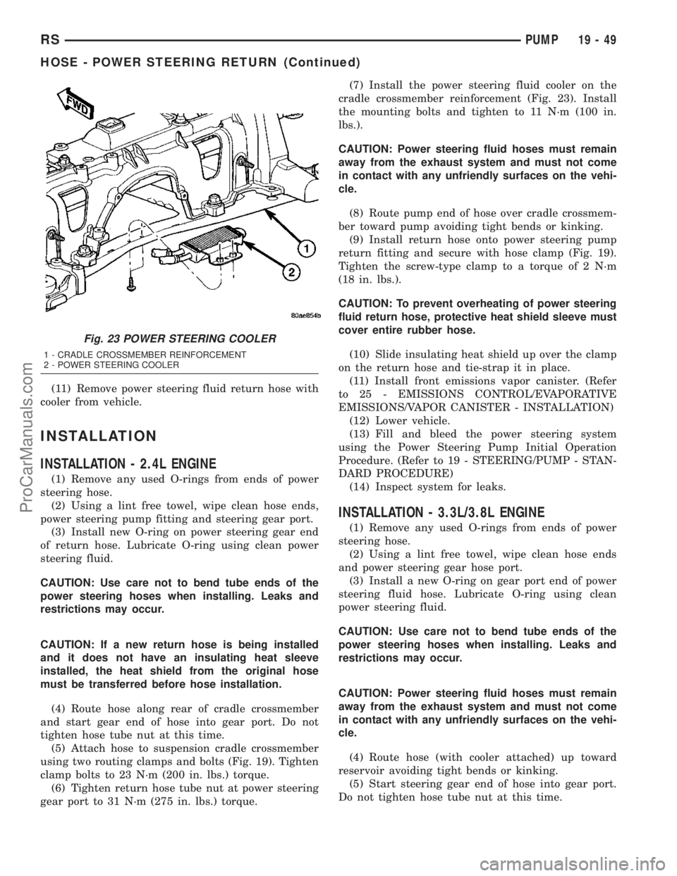
cradle crossmember reinforcement (Fig. 23). Install
the mounting bolts and tighten to 11 N´m (100 in.
lbs.).
CAUTION: Power steering fluid hoses must remain
away from the exhaust system and must not come
in contact with any unfriendly surfaces on the vehi-
cle.
(8) Route pump end of hose over cradle crossmem-
ber toward pump avoiding tight bends or kinking.
(9) Install return hose onto power steering pump
return fitting and secure with hose clamp (Fig. 19).
Tighten the screw-type clamp to a torque of 2 N´m
(18 in. lbs.).
CAUTION: To prevent overheating of power steering
fluid return hose, protective heat shield sleeve must
cover entire rubber hose.
(10) Slide insulating heat shield up over the clamp
on the return hose and tie-strap it in place.
(11) Install front emissions vapor canister. (Refer
to 25 - EMISSIONS CONTROL/EVAPORATIVE
EMISSIONS/VAPOR CANISTER - INSTALLATION)
(12) Lower vehicle.
(13) Fill and bleed the power steering system
using the Power Steering Pump Initial Operation
Procedure. (Refer to 19 - STEERING/PUMP - STAN-
DARD PROCEDURE)
(14) Inspect system for leaks.
INSTALLATION - 3.3L/3.8L ENGINE
(1) Remove any used O-rings from ends of power
steering hose.
(2) Using a lint free towel, wipe clean hose ends
and power steering gear hose port.
(3) Install a new O-ring on gear port end of power
steering fluid hose. Lubricate O-ring using clean
power steering fluid.
CAUTION: Use care not to bend tube ends of the
power steering hoses when installing. Leaks and
restrictions may occur.
CAUTION: Power steering fluid hoses must remain
away from the exhaust system and must not come
in contact with any unfriendly surfaces on the vehi-
cle.
(4) Route hose (with cooler attached) up toward
reservoir avoiding tight bends or kinking.
(5) Start steering gear end of hose into gear port.
Do not tighten hose tube nut at this time.
Fig. 23 POWER STEERING COOLER
1 - CRADLE CROSSMEMBER REINFORCEMENT
2 - POWER STEERING COOLER
RSPUMP19-49
HOSE - POWER STEERING RETURN (Continued)
ProCarManuals.com
Page 1445 of 2177

(6) Attach return hose tubes to suspension cradle
crossmember using routing clamp and bolt (Fig. 20).
Tighten clamp bolt to 23 N´m (200 in. lbs.) torque.
(7) Install the power steering fluid cooler on the
cradle crossmember reinforcement (Fig. 23). Install
the mounting bolts and tighten to 11 N´m (100 in.
lbs.). When installing mounting bolts, include pres-
sure hose routing clamp.
(8) Tighten hose tube nut at power steering gear
port to 31 N´m (275 in. lbs.) torque.
(9) Install front emissions vapor canister. (Refer to
25 - EMISSIONS CONTROL/EVAPORATIVE EMIS-
SIONS/VAPOR CANISTER - INSTALLATION)
(10) Lower vehicle.
(11) Install return hose tube into retainer on ABS
bracket (Fig. 20). Close the bracket.
(12) Install return hose onto reservoir (Fig. 21).
Slide the hose clamp into position on fluid reservoir
and attach it.Be sure hose clamp in installed
past bead on fluid reservoir fitting.
(13) Fill and bleed power steering system using
the Power Steering Pump Initial Operation Proce-
dure. (Refer to 19 - STEERING/PUMP - STANDARD
PROCEDURE)
(14) Inspect system for leaks.
HOSE - POWER STEERING
SUPPLY
REMOVAL
REMOVAL - 2.4L ENGINE
(1) Remove filler cap from power steering fluid res-
ervoir.
(2) Using a siphon pump, remove as much power
steering fluid as possible from the power steering
fluid reservoir.
(3) Raise vehicle. (Refer to LUBRICATION &
MAINTENANCE/HOISTING - STANDARD PROCE-
DURE)
(4) Remove hose clamp securing supply hose to
power steering pump, then remove supply hose from
pump fitting.
(5) Lower vehicle.
(6) Remove hose clamp attaching power steering
fluid supply hose to power steering fluid reservoir,
then remove supply hose.
(7) Remove the power steering fluid supply hose
from the vehicle.
REMOVAL - 3.3L/3.8L ENGINE
NOTE: Before proceeding, review all WARNINGS
and CAUTIONS. (Refer to 19 - STEERING/PUMP -WARNING)(Refer to 19 - STEERING/PUMP - CAU-
TION)
(1) Remove cap from power steering fluid reser-
voir.
(2) Using a siphon pump, remove as much power
steering fluid as possible from power steering fluid
reservoir.
(3) Place an oil drain pan under vehicle to catch
any draining power steering fluid.
(4) Remove clamp attaching supply hose to power
steering fluid reservoir. Disconnect hose from reser-
voir (Fig. 21).
(5) Pull upward on hose routing clip releasing it
from bracket on cylinder head cover (Fig. 21).
NOTE: It may be necessary to remove air cleaner
housing to gain greater access to supply hose at
power steering pump. (Refer to 9 - ENGINE/AIR
INTAKE SYSTEM/AIR CLEANER HOUSING -
REMOVAL)
(6) Remove clamp attaching supply hose to power
steering pump. Disconnect hose from pump and
remove from vehicle (Fig. 21).
INSTALLATION
INSTALLATION - 2.4L ENGINE
(1) Install and correctly route power steering fluid
supply hose from remote fluid reservoir to power
steering pump.
(2) Install fluid supply hose onto power steering
fluid reservoir. Install hose clamp.Be sure hose
clamp is installed past bead on fluid reservoir
fitting.
(3) Raise vehicle. (Refer to LUBRICATION &
MAINTENANCE/HOISTING - STANDARD PROCE-
DURE)
(4) Install power steering fluid supply hose on
power steering pump supply fitting. Install hose
clamp.Be sure hose clamp is installed past bead
on pump fitting.
(5) Lower vehicle.
(6) Fill and bleed power steering system using
Power Steering Pump Initial Operation Procedure.
(Refer to 19 - STEERING/PUMP - STANDARD PRO-
CEDURE)
(7) Inspect system for leaks.
INSTALLATION - 3.3L/3.8L ENGINE
(1) Install supply hose onto supply fitting on power
steering pump (Fig. 21). Slide the hose clamp into
position on fluid reservoir and attach it.Be sure
hose clamp in installed past bead on fluid res-
ervoir fitting.
19 - 50 PUMPRS
HOSE - POWER STEERING RETURN (Continued)
ProCarManuals.com
Page 1447 of 2177
INSTALLATION
INSTALLATION - 2.4L ENGINE
(1) Place reservoir into position on engine.
(2) Install reservoir mounting bolts and nut.
Tighten fasteners to 12 N´m (105 in. lbs.) torque.
(3) Install supply hose onto reservoir. Slide the
hose clamp into position on fluid reservoir and attach
it.Be sure hose clamp in installed past bead on
fluid reservoir fitting.
(4) Fill and bleed power steering system using
Power Steering Pump Initial Operation Procedure.(Refer to 19 - STEERING/PUMP - STANDARD PRO-
CEDURE)
(5) Inspect system for leaks.
INSTALLATION - 3.3L/3.8L ENGINE
(1) Place reservoir into place on engine (Fig. 21).
(2) Install reservoir mounting bolts and nut (Fig.
21). Tighten fasteners to 12 N´m (105 in. lbs.) torque.
(3) Install supply hose onto reservoir (Fig. 21).
Slide the hose clamp into position on fluid reservoir
and attach it.Be sure hose clamp in installed
past bead on fluid reservoir fitting.
(4) Install return hose onto reservoir (Fig. 21).
Slide the hose clamp into position on fluid reservoir
and attach it.Be sure hose clamp in installed
past bead on fluid reservoir fitting.
(5) Fill and bleed power steering system using
Power Steering Pump Initial Operation Procedure.
(Refer to 19 - STEERING/PUMP - STANDARD PRO-
CEDURE)
(6) Inspect system for leaks.
INSTALLATION - 2.5L DIESEL
(1) Align the guide on the rear of the reservoir
with the mounting bracket and push reservoir down-
ward until reservoir clicks into place in the bracket.
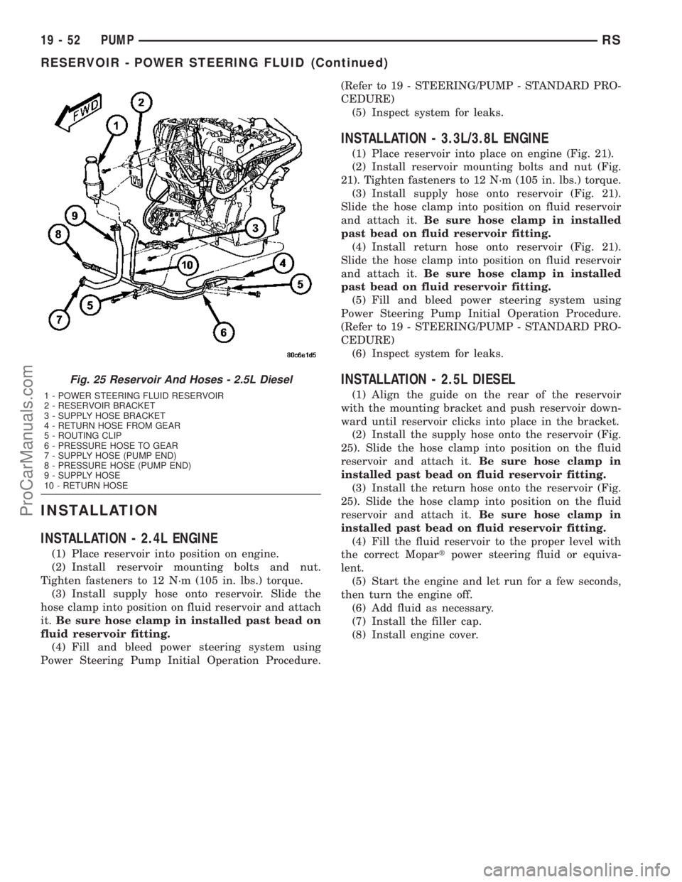
(2) Install the supply hose onto the reservoir (Fig.
25). Slide the hose clamp into position on the fluid
reservoir and attach it.Be sure hose clamp in
installed past bead on fluid reservoir fitting.
(3) Install the return hose onto the reservoir (Fig.
25). Slide the hose clamp into position on the fluid
reservoir and attach it.Be sure hose clamp in
installed past bead on fluid reservoir fitting.
(4) Fill the fluid reservoir to the proper level with
the correct Mopartpower steering fluid or equiva-
lent.
(5) Start the engine and let run for a few seconds,
then turn the engine off.
(6) Add fluid as necessary.
(7) Install the filler cap.
(8) Install engine cover.
Fig. 25 Reservoir And Hoses - 2.5L Diesel
1 - POWER STEERING FLUID RESERVOIR
2 - RESERVOIR BRACKET
3 - SUPPLY HOSE BRACKET
4 - RETURN HOSE FROM GEAR
5 - ROUTING CLIP
6 - PRESSURE HOSE TO GEAR
7 - SUPPLY HOSE (PUMP END)
8 - PRESSURE HOSE (PUMP END)
9 - SUPPLY HOSE
10 - RETURN HOSE
19 - 52 PUMPRS
RESERVOIR - POWER STEERING FLUID (Continued)
ProCarManuals.com
Page 1448 of 2177
TRANSMISSION/TRANSAXLE
TABLE OF CONTENTS
page page
POWER TRANSFER UNIT..................1
T850 MANUAL TRANSAXLE...............2141TE AUTOMATIC TRANSAXLE............116
POWER TRANSFER UNIT
TABLE OF CONTENTS
page page
POWER TRANSFER UNIT
DESCRIPTION..........................1
OPERATION............................3
DIAGNOSIS AND TESTING
SEAL IDENTIFICATION..................3
FLUID LEAK DIAGNOSIS................3
STANDARD PROCEDURE
STANDARD PROCEDURE - FLUID LEVEL
INSPECTION..........................4
STANDARD PROCEDURE - PTU FLUID
CHANGE.............................5
REMOVAL.............................5
INSTALLATION..........................6
ADJUSTMENTS
OUTPUT FLANGE SHIM SELECTION.......7
SPECIFICATIONS
TORQUE.............................7
SPECIAL TOOLS
SDP POWER TRANSFER UNIT............8
DIFFERENTIAL CARRIER SEAL
REMOVAL.............................9
INSTALLATION..........................9
END COVER BALL BEARING
REMOVAL.............................9INSTALLATION.........................10
END COVER SEAL
REMOVAL.............................11
INSTALLATION.........................11
HALF SHAFT INNER SEAL
REMOVAL.............................12
INSTALLATION.........................12
INPUT SHAFT COVER SEAL
REMOVAL.............................13
INSTALLATION.........................14
INPUT SHAFT END SEAL
REMOVAL.............................15
INSTALLATION.........................16
INPUT SHAFT SEAL
REMOVAL.............................17
INSTALLATION.........................18
OUTER HALF SHAFT SEAL
REMOVAL.............................19
INSTALLATION.........................19
REAR COVER O-RING
REMOVAL.............................19
INSTALLATION.........................20
POWER TRANSFER UNIT
DESCRIPTION
The Power Transfer Unit (P.T.U.) is attached to a
modified automatic transaxle case where the right
half shaft extension housing would normally be
located.
The Power Transfer Unit is sealed from the trans-
axle and has its own oil sump. The Unit uses MopartSAE 80W-90 Gear and Axle Lubricant (MS-9020) and
holds 1.15 liters (1.22 quarts).
Service of the Power Transfer Unit is limited to:
²Fluid Change
²Seals
²Gaskets
²One ball bearing
²Output flange
If the ring gear and pinion, any tapered roller
bearings, case, covers, or pinion carrier fail the entire
unit must be replaced.
RSTRANSMISSION/TRANSAXLE21-1
ProCarManuals.com
Page 1452 of 2177
(3) Fluid level should be within 3/16º from bottom
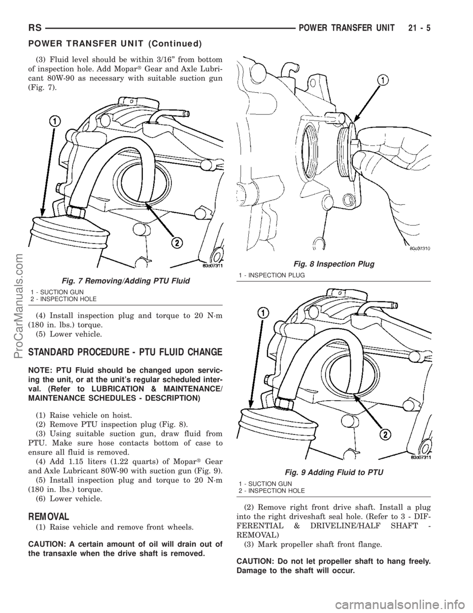
of inspection hole. Add MopartGear and Axle Lubri-
cant 80W-90 as necessary with suitable suction gun
(Fig. 7).
(4) Install inspection plug and torque to 20 N´m
(180 in. lbs.) torque.
(5) Lower vehicle.
STANDARD PROCEDURE - PTU FLUID CHANGE
NOTE: PTU Fluid should be changed upon servic-
ing the unit, or at the unit's regular scheduled inter-
val. (Refer to LUBRICATION & MAINTENANCE/
MAINTENANCE SCHEDULES - DESCRIPTION)
(1) Raise vehicle on hoist.
(2) Remove PTU inspection plug (Fig. 8).
(3) Using suitable suction gun, draw fluid from
PTU. Make sure hose contacts bottom of case to
ensure all fluid is removed.
(4) Add 1.15 liters (1.22 quarts) of MopartGear
and Axle Lubricant 80W-90 with suction gun (Fig. 9).
(5) Install inspection plug and torque to 20 N´m
(180 in. lbs.) torque.
(6) Lower vehicle.
REMOVAL
(1) Raise vehicle and remove front wheels.
CAUTION: A certain amount of oil will drain out of
the transaxle when the drive shaft is removed.(2) Remove right front drive shaft. Install a plug
into the right driveshaft seal hole. (Refer to 3 - DIF-
FERENTIAL & DRIVELINE/HALF SHAFT -
REMOVAL)
(3) Mark propeller shaft front flange.
CAUTION: Do not let propeller shaft to hang freely.
Damage to the shaft will occur.
Fig. 7 Removing/Adding PTU Fluid
1 - SUCTION GUN
2 - INSPECTION HOLE
Fig. 8 Inspection Plug
1 - INSPECTION PLUG
Fig. 9 Adding Fluid to PTU
1 - SUCTION GUN
2 - INSPECTION HOLE
RSPOWER TRANSFER UNIT21-5
POWER TRANSFER UNIT (Continued)
ProCarManuals.com
Page 1453 of 2177
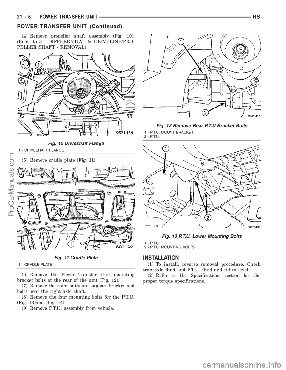
(4) Remove propeller shaft assembly (Fig. 10).
(Refer to 3 - DIFFERENTIAL & DRIVELINE/PRO-
PELLER SHAFT - REMOVAL)
(5) Remove cradle plate (Fig. 11).
(6) Remove the Power Transfer Unit mounting
bracket bolts at the rear of the unit (Fig. 12).
(7) Remove the right outboard support bracket and
bolts near the right axle shaft.
(8) Remove the four mounting bolts for the P.T.U.
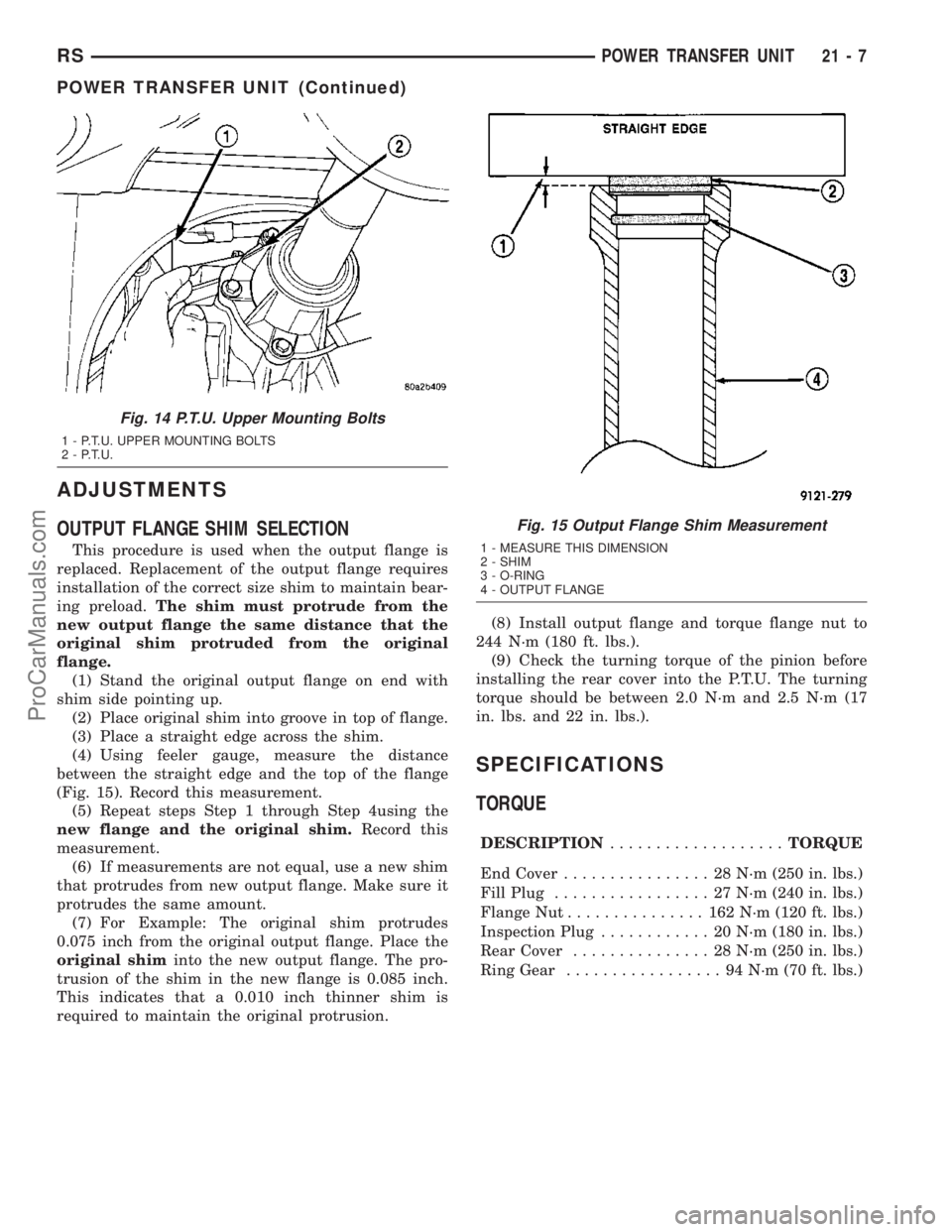
(Fig. 13)and (Fig. 14).
(9) Remove P.T.U. assembly from vehicle.
INSTALLATION
(1) To install, reverse removal procedure. Check
transaxle fluid and P.T.U. fluid and fill to level.
(2) Refer to the Specifications section for the
proper torque specifications.
Fig. 10 Driveshaft Flange
1 - DRIVESHAFT FLANGE
Fig. 11 Cradle Plate
1 - CRADLE PLATE
Fig. 12 Remove Rear P.T.U Bracket Bolts
1 - P.T.U. MOUNT BRACKET
2 - P.T.U.
Fig. 13 P.T.U. Lower Mounting Bolts
1 - P.T.U.
2 - P.T.U. MOUNTING BOLTS
21 - 6 POWER TRANSFER UNITRS
POWER TRANSFER UNIT (Continued)
ProCarManuals.com
Page 1454 of 2177
ADJUSTMENTS
OUTPUT FLANGE SHIM SELECTION
This procedure is used when the output flange is
replaced. Replacement of the output flange requires
installation of the correct size shim to maintain bear-
ing preload.The shim must protrude from the
new output flange the same distance that the
original shim protruded from the original
flange.
(1) Stand the original output flange on end with
shim side pointing up.
(2) Place original shim into groove in top of flange.
(3) Place a straight edge across the shim.
(4) Using feeler gauge, measure the distance
between the straight edge and the top of the flange
(Fig. 15). Record this measurement.
(5) Repeat steps Step 1 through Step 4using the
new flange and the original shim.Record this
measurement.
(6) If measurements are not equal, use a new shim
that protrudes from new output flange. Make sure it
protrudes the same amount.
(7) For Example: The original shim protrudes
0.075 inch from the original output flange. Place the
original shiminto the new output flange. The pro-
trusion of the shim in the new flange is 0.085 inch.
This indicates that a 0.010 inch thinner shim is
required to maintain the original protrusion.(8) Install output flange and torque flange nut to
244 N´m (180 ft. lbs.).
(9) Check the turning torque of the pinion before
installing the rear cover into the P.T.U. The turning
torque should be between 2.0 N´m and 2.5 N´m (17
in. lbs. and 22 in. lbs.).
SPECIFICATIONS
TORQUE
DESCRIPTION...................TORQUE
End Cover................ 28N´m(250 in. lbs.)
Fill Plug................. 27N´m(240 in. lbs.)
Flange Nut............... 162N´m(120 ft. lbs.)
Inspection Plug............ 20N´m(180 in. lbs.)
Rear Cover............... 28N´m(250 in. lbs.)
Ring Gear................. 94N´m(70ft.lbs.)
Fig. 14 P.T.U. Upper Mounting Bolts
1 - P.T.U. UPPER MOUNTING BOLTS
2 - P.T.U.
Fig. 15 Output Flange Shim Measurement
1 - MEASURE THIS DIMENSION
2 - SHIM
3 - O-RING
4 - OUTPUT FLANGE
RSPOWER TRANSFER UNIT21-7
POWER TRANSFER UNIT (Continued)
ProCarManuals.com
Page 1468 of 2177

T850 MANUAL TRANSAXLE
TABLE OF CONTENTS
page page
T850 MANUAL TRANSAXLE
DESCRIPTION.........................21
OPERATION...........................24
DIAGNOSIS AND TESTING - COMMON
PROBLEM CAUSES....................30
REMOVAL.............................31
DISASSEMBLY.........................35
ASSEMBLY............................42
INSTALLATION.........................51
SPECIFICATIONS - T850 MANUAL
TRANSAXLE.........................56
SPECIAL TOOLS - T850 TRANSAXLE........58
AXLE SEALS
REMOVAL.............................61
INSTALLATION.........................61
BACK-UP LAMP SWITCH
REMOVAL.............................62
INSTALLATION.........................62
DIFFERENTIAL
DESCRIPTION.........................62
OPERATION...........................62
DISASSEMBLY.........................62
ASSEMBLY............................66
ADJUSTMENTS
ADJUSTMENT - DIFFERENTIAL TURNING
TORQUE............................69
ADJUSTMENT - DIFFERENTIAL SIDE GEAR
ENDPLAY...........................70
FLUID
STANDARD PROCEDURE
STANDARD PROCEDURE - FLUID LEVEL
CHECK.............................71
STANDARD PROCEDURE - FLUID DRAIN
AND FILL............................71
GEARSHIFT BOOT
REMOVAL.............................72
INSTALLATION.........................73GEARSHIFT CABLE - CROSSOVER
REMOVAL.............................73
INSTALLATION.........................76
ADJUSTMENTS
ADJUSTMENT........................79
GEARSHIFT CABLE - SELECTOR
REMOVAL.............................81
INSTALLATION.........................84
GEARSHIFT KNOB
REMOVAL.............................87
INSTALLATION.........................87
GEARSHIFT MECHANISM
REMOVAL.............................87
INSTALLATION.........................89
INPUT SHAFT
DESCRIPTION.........................93
DISASSEMBLY.........................93
ASSEMBLY............................96
INTERMEDIATE SHAFT
DESCRIPTION........................100
DISASSEMBLY........................100
ASSEMBLY...........................107
SHIFT COVER
DESCRIPTION........................113
SHIFT FORK AND SHAFT
DESCRIPTION........................113
SYNCHRONIZER
DESCRIPTION........................114
DISASSEMBLY........................114
CLEANING
CLEAN.............................114
INSPECTION
INSPECT...........................114
ASSEMBLY...........................114
VEHICLE SPEED SENSOR
REMOVAL............................115
INSTALLATION........................115
T850 MANUAL TRANSAXLE
DESCRIPTION
The NV T850 5-speed transaxle (Fig. 1) is a con-
stant-mesh manual transaxle that is synchronized in
all gear ranges, including reverse.The transaxle consists of three major sub-assem-
blies: the input shaft, intermediate shaft, and differ-
ential assembly. The transaxle shift system consists
of a mechanical shift cover, rails, forks, and cables.
The unique design of this shift system provides a
higher mechanical advantage, resulting in less fric-
tion and lower shift cable loads for smoother, more
positive operation.
RST850 MANUAL TRANSAXLE21-21
ProCarManuals.com
Page 1487 of 2177
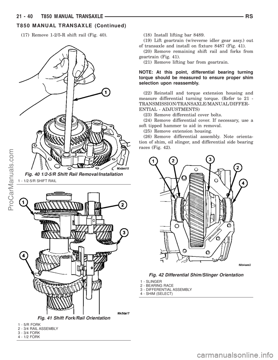
(17) Remove 1-2/5-R shift rail (Fig. 40). (18) Install lifting bar 8489.
(19) Lift geartrain (w/reverse idler gear assy.) out
of transaxle and install on fixture 8487 (Fig. 41).
(20) Remove remaining shift rail and forks from
geartrain (Fig. 41).
(21) Remove lifting bar from geartrain.
NOTE: At this point, differential bearing turning
torque should be measured to ensure proper shim
selection upon reassembly.
(22) Reinstall and torque extension housing and
measure differential turning torque. (Refer to 21 -
TRANSMISSION/TRANSAXLE/MANUAL/DIFFER-
ENTIAL - ADJUSTMENTS)
(23) Remove differential cover bolts.
(24) Remove differential cover. If necessary, use a
soft tipped hammer to aid in removal.
(25) Remove extension housing.
(26) Remove differential assembly. Note orienta-
tion of shim, oil slinger, and differential side bearing
races (Fig. 42).
Fig. 40 1/2-5/R Shift Rail Removal/Installation
1 - 1/2-5/R SHIFT RAIL
Fig. 41 Shift Fork/Rail Orientation
1 - 5/R FORK
2 - 3/4 RAIL ASSEMBLY
3 - 3/4 FORK
4 - 1/2 FORK
Fig. 42 Differential Shim/Slinger Orientation
1 - SLINGER
2 - BEARING RACE
3 - DIFFERENTIAL ASSEMBLY
4 - SHIM (SELECT)
21 - 40 T850 MANUAL TRANSAXLERS
T850 MANUAL TRANSAXLE (Continued)
ProCarManuals.com
Page 1489 of 2177
ASSEMBLY
NOTE: When assembling this transaxle, always use
NEW snap rings.
NOTE: Before assembling transaxle, differential
turning torque must be measured and adjusted.
(Refer to 21 - TRANSMISSION/TRANSAXLE/MANU-
AL/DIFFERENTIAL - ADJUSTMENTS). Differential
turning torque must be measured with geartrain out
of case.
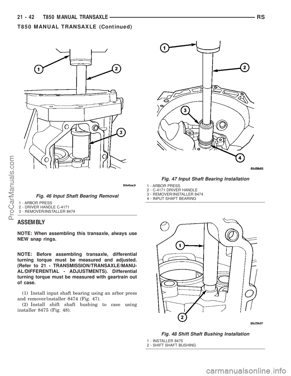
(1) Install input shaft bearing using an arbor press
and remover/installer 8474 (Fig. 47).
(2) Install shift shaft bushing to case using
installer 8475 (Fig. 48).
Fig. 46 Input Shaft Bearing Removal
1 - ARBOR PRESS
2 - DRIVER HANDLE C-4171
3 - REMOVER/INSTALLER 8474
Fig. 47 Input Shaft Bearing Installation
1 - ARBOR PRESS
2 - C-4171 DRIVER HANDLE
3 - REMOVER/INSTALLER 8474
4 - INPUT SHAFT BEARING
Fig. 48 Shift Shaft Bushing Installation
1 - INSTALLER 8475
2 - SHIFT SHAFT BUSHING
21 - 42 T850 MANUAL TRANSAXLERS
T850 MANUAL TRANSAXLE (Continued)
ProCarManuals.com