torque CHRYSLER VOYAGER 2003 Service Manual
[x] Cancel search | Manufacturer: CHRYSLER, Model Year: 2003, Model line: VOYAGER, Model: CHRYSLER VOYAGER 2003Pages: 2177, PDF Size: 59.81 MB
Page 1491 of 2177
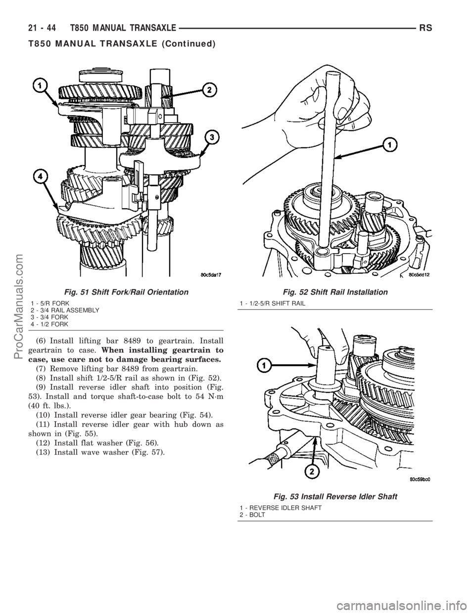
(6) Install lifting bar 8489 to geartrain. Install
geartrain to case.When installing geartrain to
case, use care not to damage bearing surfaces.
(7) Remove lifting bar 8489 from geartrain.
(8) Install shift 1/2-5/R rail as shown in (Fig. 52).
(9) Install reverse idler shaft into position (Fig.
53). Install and torque shaft-to-case bolt to 54 N´m
(40 ft. lbs.).
(10) Install reverse idler gear bearing (Fig. 54).
(11) Install reverse idler gear with hub down as
shown in (Fig. 55).
(12) Install flat washer (Fig. 56).
(13) Install wave washer (Fig. 57).
Fig. 51 Shift Fork/Rail Orientation
1 - 5/R FORK
2 - 3/4 RAIL ASSEMBLY
3 - 3/4 FORK
4 - 1/2 FORK
Fig. 52 Shift Rail Installation
1 - 1/2-5/R SHIFT RAIL
Fig. 53 Install Reverse Idler Shaft
1 - REVERSE IDLER SHAFT
2 - BOLT
21 - 44 T850 MANUAL TRANSAXLERS
T850 MANUAL TRANSAXLE (Continued)
ProCarManuals.com
Page 1493 of 2177

(14) Install input shaft sealed roller bearing using
installer 8482 (Fig. 58).
(15) Installnewinput shaft bearing snap ring
(Fig. 59).(16) Install shift rail bushing to end cover using
installer 8475 (Fig. 60).
(17) Applya1mm(0.04 in.) bead of MopartGas-
ket Maker to transaxle end cover and install to
transaxle case (Fig. 61).While installing end
cover, be sure to guide oil trough into pocket
(Fig. 62).Torque end cover-to-case bolts to 28 N´m
(250 in. lbs.) (Fig. 63).
Fig. 58 Install Input Shaft Sealed Roller Bearing
1 - INSTALLER 8482
2 - SEALED ROLLER BEARING
Fig. 59 Input Shaft Bearing Snap Ring
1 - SNAP RING
Fig. 60 Shift Rail Bushing Installation
1 - INSTALLER 8475
Fig. 61 End Cover Removal/Installation
1 - END COVER
2 - OIL TROUGH
21 - 46 T850 MANUAL TRANSAXLERS
T850 MANUAL TRANSAXLE (Continued)
ProCarManuals.com
Page 1494 of 2177
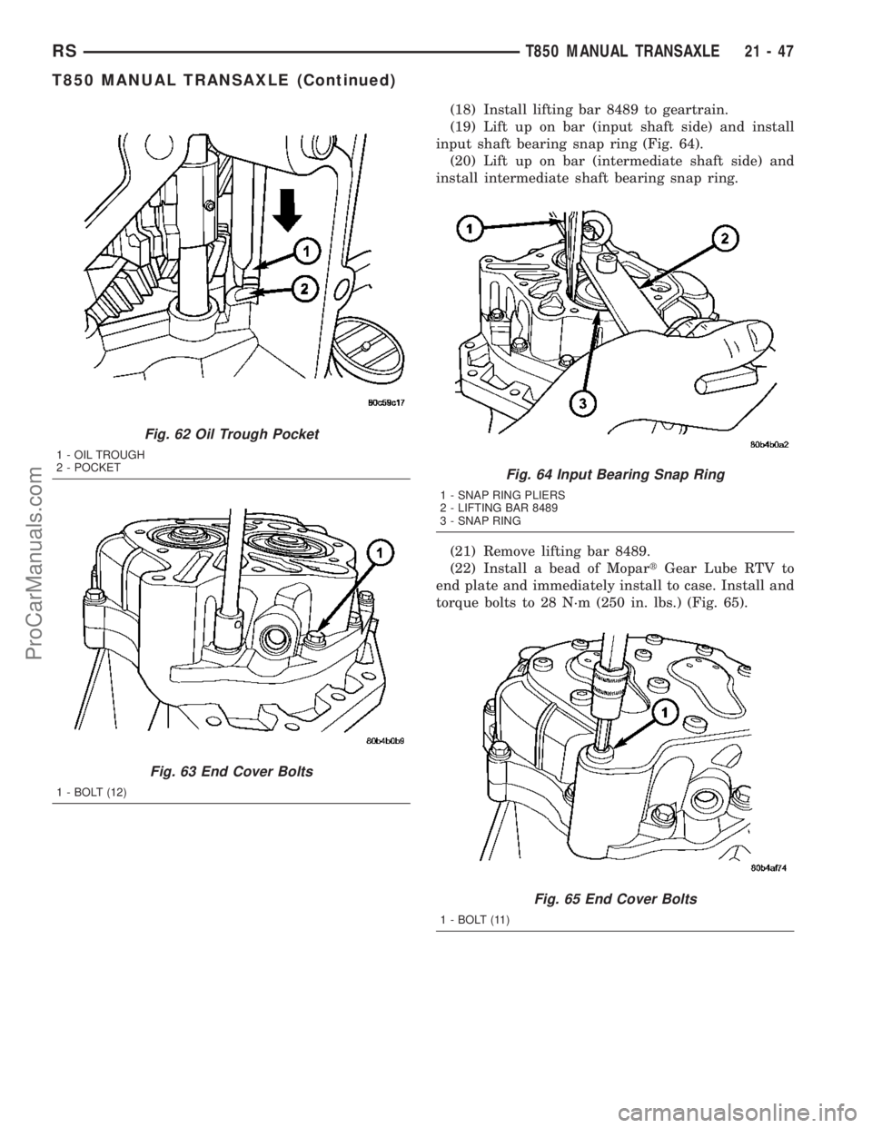
(18) Install lifting bar 8489 to geartrain.
(19) Lift up on bar (input shaft side) and install
input shaft bearing snap ring (Fig. 64).
(20) Lift up on bar (intermediate shaft side) and
install intermediate shaft bearing snap ring.
(21) Remove lifting bar 8489.
(22) Install a bead of MopartGear Lube RTV to
end plate and immediately install to case. Install and
torque bolts to 28 N´m (250 in. lbs.) (Fig. 65).
Fig. 62 Oil Trough Pocket
1 - OIL TROUGH
2 - POCKET
Fig. 63 End Cover Bolts
1 - BOLT (12)
Fig. 64 Input Bearing Snap Ring
1 - SNAP RING PLIERS
2 - LIFTING BAR 8489
3 - SNAP RING
Fig. 65 End Cover Bolts
1 - BOLT (11)
RST850 MANUAL TRANSAXLE21-47
T850 MANUAL TRANSAXLE (Continued)
ProCarManuals.com
Page 1495 of 2177
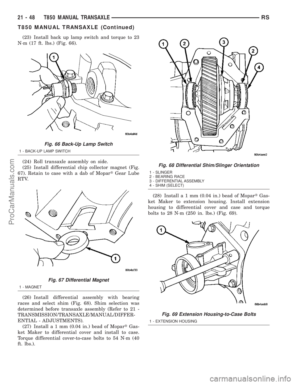
(23) Install back up lamp switch and torque to 23
N´m (17 ft. lbs.) (Fig. 66).
(24) Roll transaxle assembly on side.
(25) Install differential chip collector magnet (Fig.
67). Retain to case with a dab of MopartGear Lube
RTV.
(26) Install differential assembly with bearing
races and select shim (Fig. 68). Shim selection was
determined before transaxle assembly (Refer to 21 -
TRANSMISSION/TRANSAXLE/MANUAL/DIFFER-
ENTIAL - ADJUSTMENTS).
(27) Installa1mm(0.04 in.) bead of MopartGas-
ket Maker to differential cover and install to case.
Torque differential cover-to-case bolts to 54 N´m (40
ft. lbs.).(28) Installa1mm(0.04 in.) bead of MopartGas-
ket Maker to extension housing. Install extension
housing to differential cover and case and torque
bolts to 28 N´m (250 in. lbs.) (Fig. 69).
Fig. 66 Back-Up Lamp Switch
1 - BACK-UP LAMP SWITCH
Fig. 67 Differential Magnet
1 - MAGNET
Fig. 68 Differential Shim/Slinger Orientation
1 - SLINGER
2 - BEARING RACE
3 - DIFFERENTIAL ASSEMBLY
4 - SHIM (SELECT)
Fig. 69 Extension Housing-to-Case Bolts
1 - EXTENSION HOUSING
21 - 48 T850 MANUAL TRANSAXLERS
T850 MANUAL TRANSAXLE (Continued)
ProCarManuals.com
Page 1496 of 2177
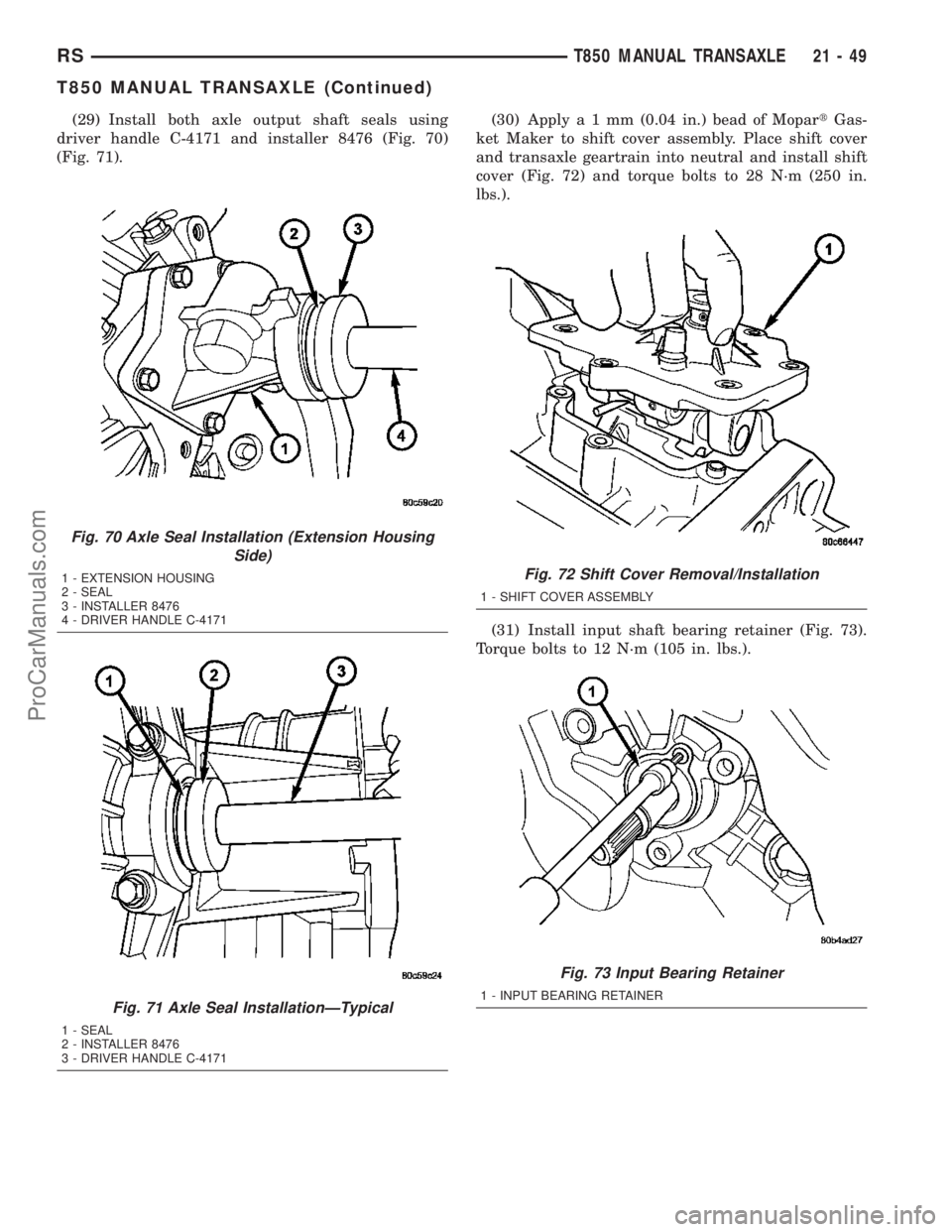
(29) Install both axle output shaft seals using
driver handle C-4171 and installer 8476 (Fig. 70)
(Fig. 71).(30) Applya1mm(0.04 in.) bead of MopartGas-
ket Maker to shift cover assembly. Place shift cover
and transaxle geartrain into neutral and install shift
cover (Fig. 72) and torque bolts to 28 N´m (250 in.
lbs.).
(31) Install input shaft bearing retainer (Fig. 73).
Torque bolts to 12 N´m (105 in. lbs.).
Fig. 70 Axle Seal Installation (Extension Housing
Side)
1 - EXTENSION HOUSING
2 - SEAL
3 - INSTALLER 8476
4 - DRIVER HANDLE C-4171
Fig. 71 Axle Seal InstallationÐTypical
1 - SEAL
2 - INSTALLER 8476
3 - DRIVER HANDLE C-4171
Fig. 72 Shift Cover Removal/Installation
1 - SHIFT COVER ASSEMBLY
Fig. 73 Input Bearing Retainer
1 - INPUT BEARING RETAINER
RST850 MANUAL TRANSAXLE21-49
T850 MANUAL TRANSAXLE (Continued)
ProCarManuals.com
Page 1498 of 2177

INSTALLATION
INSTALLATION - 2.4L GAS
(1) Install modular clutch assembly to transaxle.
Assemble transaxle to engine.
(2) Install and torque transaxle-to-engine bolts to
95 N´m (70 ft. lbs.).
(3) Raise transaxle/engine assembly into position
and install upper mount through-bolt. Torque
through-bolt to 75 N´m (55 ft. lbs.).
(4) Remove screw jack.
(5) Install and torque modular clutch assembly-to-
drive plate bolts to 88 N´m (65 ft. lbs.)
(6) Install structural collar.
(7) Connect back-up lamp switch connector.
(8) Install starter motor into position (Fig. 78).
Install and torque bolts to 54 N´m (40 ft. lbs.).
(9) Install engine front mount bracket. Install and
torque bracket-to-transaxle bolts to 102 N´m (75 ft.
lbs.). Install and torque bracket-to-engine bolts to 68
N´m (50 ft. lbs.). Torque through-bolt and nut to 68
N´m (50 ft. lbs.).(10) Install clutch slave cylinder into position, not-
ing orientation of different sized lugs (Fig. 79). While
depressing inward, rotate slave cylinder clockwise
60tÉ into position until nylon locating tab rests
within transaxle case cutout, and hydraulic tube is
vertical. Connect ªquick-connectº connection until an
audible ªclickº is heard. Verify connection by pulling
outward on connection.
(11) Install halfshafts and front wheel/tire assem-
blies. (Refer to 3 - DIFFERENTIAL & DRIVELINE/
HALF SHAFT - INSTALLATION)
(12) Lower vehicle.
Fig. 78 Starter Motor Removal/Installation
1 - STARTER MOTOR
2 - BOLT (3)
Fig. 79 Slave Cylinder Removal/Installation
1 - MOUNTING HOLE
2 - SLAVE CYLINDER
3 - ACCESS HOLE
4 - NYLON ANTI-ROTATION TAB
5 - QUICK CONNECT
RST850 MANUAL TRANSAXLE21-51
T850 MANUAL TRANSAXLE (Continued)
ProCarManuals.com
Page 1499 of 2177

(13) Install right mount bracket to transaxle (Fig.
80).
(14) Connect gearshift cables to shift levers/cover
assembly (Fig. 81). Install cables into position at
mount bracket and secure with retaining clips.
(15) Connect battery cables.
(16) Check transaxle fluid and engine coolant lev-
els. Adjust if necessary. (Refer to 21 - TRANSMIS-
SION/TRANSAXLE/MANUAL/FLUID - STANDARD
PROCEDURE)
INSTALLATION - 2.5L TD
(1) Assemble transaxle to engine, while aligning
transaxle input shaft to clutch disc splines.
(2) Install and torque transaxle-to-engine bolts to
95 N´m (70 ft. lbs.) (Fig. 82).
(3) Install transaxle upper mount (Fig. 83). Install
and torque four (4) mount-to-transaxle bolts to 54
N´m (40 ft. lbs.).
(4) Raise transaxle/engine assembly into position
and install upper mount through-bolt. Torque
through-bolt to 75 N´m (55 ft. lbs.).
(5) Remove screw jack.
(6) Connect back-up lamp switch connector.
(7) Install starter motor into position (Fig. 84).
Install and torque bolts to 54 N´m (40 ft. lbs.).
Fig. 80 Transaxle Right Mount and Bracket
1 - MOUNT BRACKET
2 - BOLT (3)
3 - MOUNT
4 - BOLT (1)
Fig. 81 Gearshift Cables at Transaxle
1 - SELECTOR CABLE
2 - CABLE RETAINER
3 - CABLE RETAINER
4 - CROSSOVER CABLE
5 - MOUNT BRACKET
21 - 52 T850 MANUAL TRANSAXLERS
T850 MANUAL TRANSAXLE (Continued)
ProCarManuals.com
Page 1501 of 2177

(8) Install engine front mount bracket. Install and
torque bracket-to-transaxle bolts to 102 N´m (75 ft.
lbs.). Install and torque bracket-to-engine bolts to 68
N´m (50 ft. lbs.). Torque through-bolt and nut to 68
N´m (50 ft. lbs.).
(9) Install clutch slave cylinder into position, not-
ing orientation of different sized lugs (Fig. 85). While
depressing inward, rotate slave cylinder clockwise
60É into position until nylon locating tab rests within
transaxle case cutout, and hydraulic tube is vertical.
Connect ªquick-connectº connection until an audible
ªclickº is heard. Verify connection by pulling outward
on connection.
(10) Install underbody splash panel.
(11) Install halfshafts and front wheel/tire assem-
blies. (Refer to 3 - DIFFERENTIAL & DRIVELINE/
HALF SHAFT - INSTALLATION)
(12) Lower vehicle.
(13) Install right mount bracket to transaxle (Fig.
86).
(14) Connect gearshift cables to shift levers/cover
assembly (Fig. 87). Install cables into position at
mount bracket and secure with retaining clips.
Fig. 85 Slave Cylinder Removal/Installation
1 - MOUNTING HOLE
2 - SLAVE CYLINDER
3 - ACCESS HOLE
4 - NYLON ANTI-ROTATION TAB
5 - QUICK CONNECT
Fig. 86 Transaxle Right Mount and Bracket
1 - MOUNT BRACKET
2 - BOLT (3)
3 - MOUNT
4 - BOLT (1)
Fig. 87 Gearshift Cables at Transaxle
1 - SELECTOR CABLE
2 - CABLE RETAINER
3 - CABLE RETAINER
4 - CROSSOVER CABLE
5 - MOUNT BRACKET
21 - 54 T850 MANUAL TRANSAXLERS
T850 MANUAL TRANSAXLE (Continued)
ProCarManuals.com
Page 1504 of 2177
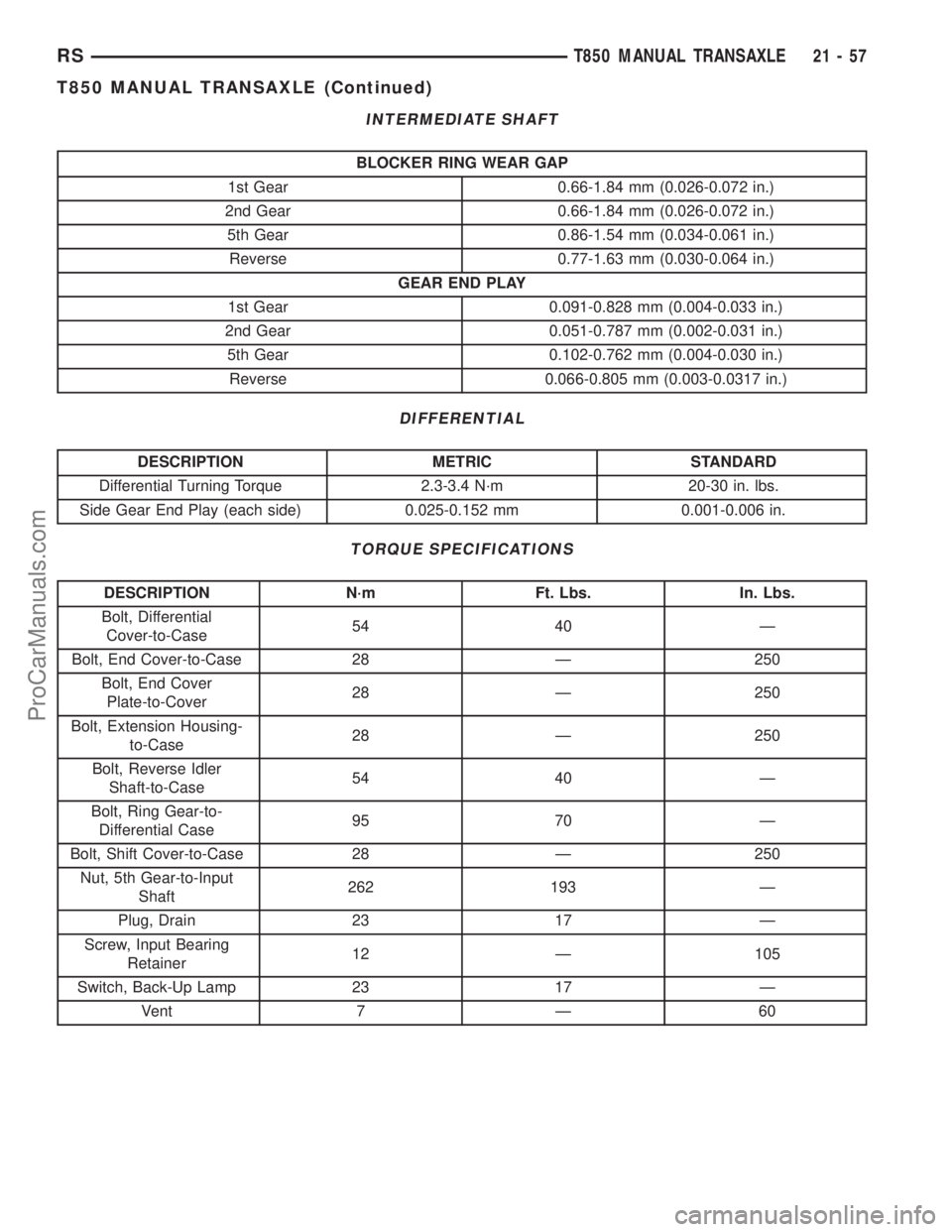
INTERMEDIATE SHAFT
BLOCKER RING WEAR GAP
1st Gear 0.66-1.84 mm (0.026-0.072 in.)
2nd Gear 0.66-1.84 mm (0.026-0.072 in.)
5th Gear 0.86-1.54 mm (0.034-0.061 in.)
Reverse 0.77-1.63 mm (0.030-0.064 in.)
GEAR END PLAY
1st Gear 0.091-0.828 mm (0.004-0.033 in.)
2nd Gear 0.051-0.787 mm (0.002-0.031 in.)
5th Gear 0.102-0.762 mm (0.004-0.030 in.)
Reverse 0.066-0.805 mm (0.003-0.0317 in.)
DIFFERENTIAL
DESCRIPTION METRIC STANDARD
Differential Turning Torque 2.3-3.4 N´m 20-30 in. lbs.
Side Gear End Play (each side) 0.025-0.152 mm 0.001-0.006 in.
TORQUE SPECIFICATIONS
DESCRIPTION N´m Ft. Lbs. In. Lbs.
Bolt, Differential
Cover-to-Case54 40 Ð
Bolt, End Cover-to-Case 28 Ð 250
Bolt, End Cover
Plate-to-Cover28 Ð 250
Bolt, Extension Housing-
to-Case28 Ð 250
Bolt, Reverse Idler
Shaft-to-Case54 40 Ð
Bolt, Ring Gear-to-
Differential Case95 70 Ð
Bolt, Shift Cover-to-Case 28 Ð 250
Nut, 5th Gear-to-Input
Shaft262 193 Ð
Plug, Drain 23 17 Ð
Screw, Input Bearing
Retainer12 Ð 105
Switch, Back-Up Lamp 23 17 Ð
Vent 7 Ð 60
RST850 MANUAL TRANSAXLE21-57
T850 MANUAL TRANSAXLE (Continued)
ProCarManuals.com
Page 1505 of 2177
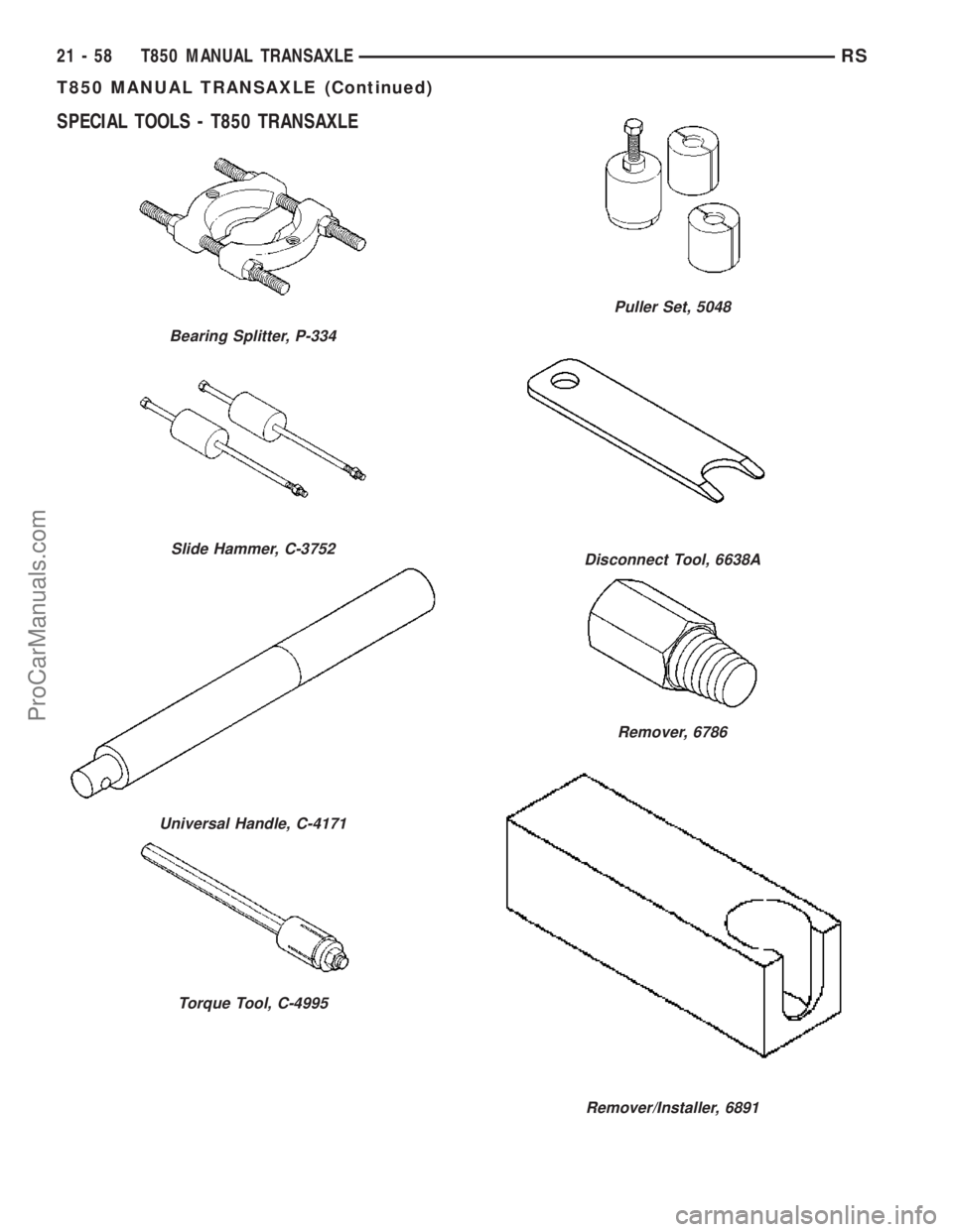
SPECIAL TOOLS - T850 TRANSAXLE
Bearing Splitter, P-334
Slide Hammer, C-3752
Universal Handle, C-4171
Torque Tool, C-4995
Puller Set, 5048
Disconnect Tool, 6638A
Remover, 6786
Remover/Installer, 6891
21 - 58 T850 MANUAL TRANSAXLERS
T850 MANUAL TRANSAXLE (Continued)
ProCarManuals.com