heater CHRYSLER VOYAGER 2004 Owner's Manual
[x] Cancel search | Manufacturer: CHRYSLER, Model Year: 2004, Model line: VOYAGER, Model: CHRYSLER VOYAGER 2004Pages: 2585, PDF Size: 62.54 MB
Page 503 of 2585
Refer to the description of the heated seat switch
later in this section for additional information.
Hard wired circuitry connects the heated seat sys-
tem components to each other through the electrical
system of the vehicle. These hard wired circuits are
integral to several wire harnesses, which are routed
throughout the vehicle and retained by many differ-
ent methods. These circuits may be connected to each
other, to the vehicle electrical system and to the
heated seat system components through the use of a
combination of soldered splices and splice block con-
nectors. Refer to Wiring for complete system wiring
schematics. The wiring information also includes the
proper wire and connector repair procedures, further
details on wire harness routing and retention, as well
as pin-out and location views for the various wire
harness connectors, splices and grounds.
OPERATION
The heated seat system components operate on
battery current received through a fuse in the Inte-
grated Power Module (IPM) on a fused ignition
switch output (run) circuit from the Body Control
Module. The system will only operate when the igni-
tion switch is in the On position. The heated seat
system will be turned Off automatically whenever
the ignition switch is turned to any position except
On. Also, the heated seat system will not operate
when the surface temperature of the seat cushion
cover at either heated seat sensor is above the
designed temperature set points of the system. See
the owner's manual in the vehicle glove box for more
information on the features, use and operation of the
heated seat system.
DIAGNOSIS AND TESTING - HEATED SEAT
SYSTEM
The most reliable, efficient, and accurate means to
diagnose the heated seat system requires the use of a
DRBIIItscan tool and the proper Diagnostic Proce-
dures manual. The DRBIIItscan tool can provide
confirmation that the PCI data bus is functional, that
all of the electronic modules are sending and receiv-
ing the proper messages on the PCI data bus, and
that the heated seat modules are receiving the
proper hard wired inputs from and relaying the
proper hard wired outputs to the Body Control Mod-
ule in order to perform its functions. Refer toWiring
Diagramsfor complete wiring schematics. The wir-
ing information also includes the proper wire and
connector repair procedures, further details on wire
harness routing and retention, as well as pin-out and
location views for the various wire harness connec-
tors, splices and grounds.
DRIVER HEATED SEAT
SWITCH
DESCRIPTION
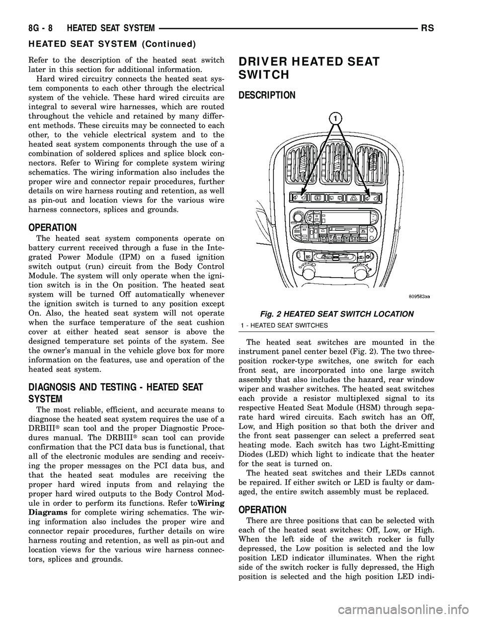
The heated seat switches are mounted in the
instrument panel center bezel (Fig. 2). The two three-
position rocker-type switches, one switch for each
front seat, are incorporated into one large switch
assembly that also includes the hazard, rear window
wiper and washer switches. The heated seat switches
each provide a resistor multiplexed signal to its
respective Heated Seat Module (HSM) through sepa-
rate hard wired circuits. Each switch has an Off,
Low, and High position so that both the driver and
the front seat passenger can select a preferred seat
heating mode. Each switch has two Light-Emitting
Diodes (LED) which light to indicate that the heater
for the seat is turned on.
The heated seat switches and their LEDs cannot
be repaired. If either switch or LED is faulty or dam-
aged, the entire switch assembly must be replaced.
OPERATION
There are three positions that can be selected with
each of the heated seat switches: Off, Low, or High.
When the left side of the switch rocker is fully
depressed, the Low position is selected and the low
position LED indicator illuminates. When the right
side of the switch rocker is fully depressed, the High
position is selected and the high position LED indi-
Fig. 2 HEATED SEAT SWITCH LOCATION
1 - HEATED SEAT SWITCHES
8G - 8 HEATED SEAT SYSTEMRS
HEATED SEAT SYSTEM (Continued)
Page 504 of 2585
cator illuminates. When the switch rocker is moved
to its neutral position (middle), Off is selected and
both LED indicators are extinguished.
Each switch provides separate resistor multiplexed
hard wire inputs to its respective Heated Seat Mod-
ule (HSM) to indicate the selected switch position.
The heated seat module responds to the heated seat
switch status messages by controlling the output to
the seat heater elements of the selected seat. The
Low heat position set point is about 36É C (97É F),
and the High heat position set point is about 41É C
(105É F).
DIAGNOSIS AND TESTING - DRIVER HEATED
SEAT SWITCH
For complete circuit diagrams, refer toWiring
Diagrams.
WARNING: REFER TO THE RESTRAINTS SECTION
OF THIS MANUAL BEFORE ATTEMPTING ANY
STEERING WHEEL, STEERING COLUMN, SEAT OR
INSTRUMENT PANEL COMPONENT DIAGNOSIS OR
SERVICE. FAILURE TO TAKE THE PROPER PRE-
CAUTIONS COULD RESULT IN ACCIDENTAL AIR-
BAG DEPLOYMENT AND POSSIBLE PERSONAL
INJURY.
CHECKING SWITCH SIGNAL AND WIRING AT THE
MODULE
(1) Disconnect and isolate the battery negative
cable.
(2) Access and disconnect the gray 4-way connector
from the heated seat module. Visually inspect wiring
terminals for damage that would prevent positive
connection. If not OK, repair or replace the necessary
components.
(3) Place the heated seat switch in the LO posi-
tion. Using an Ohmmeter, check the resistance
between cavities 2 and 3 of the gray connector noted
above. Resistance should be about 3.5 kilohms (3500
ohms). If not OK, check resistance directly at switch,
as noted below. If OK, proceed to the next step. If not
OK, replace the faulty switch.
(4) Place the heated seat switch in the HI position.
Using an ohmmeter, check the resistance between
cavities 2 and 3 of the gray connector noted above.
Resistance should be about 1.4 kilohms (1400 ohms).
If not OK, check resistance directly at switch, as
noted below. If OK, proceed. If not OK replace the
faulty switch.
(5) With the system ON in the HI position, check
for battery voltage and ground at cavities 4 and 1. If
OK, proceed with testing remaining components. If
not OK, repair open or shorted wiring.
CHECKING SWITCH ONLY
(1) Disconnect and isolate the battery negative
cable. Remove the center bezel from the instrument
panel (Refer to 23 - BODY/INSTRUMENT PANEL/
INSTRUMENT PANEL CENTER BEZEL -
REMOVAL). Check for continuity between the
ground circuit cavity (#10) of the instrument panel
switch bank electrical connector and a good ground.
There should be continuity. If OK, go to Step 2. If not
OK, repair the open ground circuit to ground as
required.
(2) Reconnect the battery negative cable. Turn the
ignition switch to the On position. Check for battery
voltage at the fused ignition switch output (run) cir-
cuit cavity of the instrument panel switch bank con-
nector (#4). If OK, turn the ignition switch to the Off
position, and go to Step 3. If not OK, repair the open
fused ignition switch output (run) circuit as required.
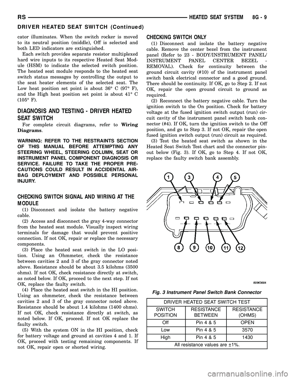
(3) Test the heated seat switch as shown in the
Heated Seat Switch Test chart and the connector pin-
out below (Fig. 3). If OK, go to Step 4. If not OK,
replace the faulty switch bank assembly.
DRIVER HEATED SEAT SWITCH TEST
SWITCH
POSITIONRESISTANCE
BETWEENRESISTANCE
(OHMS)
Off Pin4&5OPEN
Low Pin4&53570
High Pin4&51430
All resistance values are 1%.
Fig. 3 Instrument Panel Switch Bank Connector
RSHEATED SEAT SYSTEM8G-9
DRIVER HEATED SEAT SWITCH (Continued)
Page 507 of 2585
(3) Connect the negative battery cable.
(4) Verify heated seat system operation.
(5) Install the appropriate seat cushion or seat
back trim cover. Make certain the seat wire harness
is correctly routed through the seat and seat back.
The excess wire between the cushion and back ele-
ments should be securely tucked between the rear of
the cushion foam and the rear carpet flap of the trim
cover.
HEATED SEAT SENSOR
DESCRIPTION
Two heated seat sensors are used per vehicle, one
in each front seat cushion heating element. The
heated seat temperature sensor is a Negative Tem-
perature Coefficient (NTC) thermistor.
The heated seat sensors cannot be repaired or
adjusted and if found to be faulty, the complete
heated seat cushion element must be replaced.
OPERATION
The temperature sensor is a NTC thermistor.
When the temperature of the seat cushion cover
rises, the resistance of the sensor decreases. The
heated seat module supplies a five-volt current to one
side of each sensor, and monitors the voltage drop
through the sensor on a return circuit. The heated
seat module uses this temperature sensor input to
monitor the temperature of the seat, and regulates
the current flow to the seat heating elements accord-
ingly.
DIAGNOSIS AND TESTING - HEATED SEAT
SENSOR
For complete circuit diagrams, refer toWiring
Diagrams.
(1) Disconnect and isolate the battery negative
cable. Disconnect the green 4-way heated seat mod-
ule wire harness connector.
(2) Using an ohmmeter, check the resistance
between cavities 2 and 3. The sensor resistance
should be between 50 kilohms at 15É C (60É F) and 2
kilohms at 30É C (85É F). If not OK, replace the
faulty seat element and sensor assembly.
PASSENGER HEATED SEAT
SWITCH
DESCRIPTION
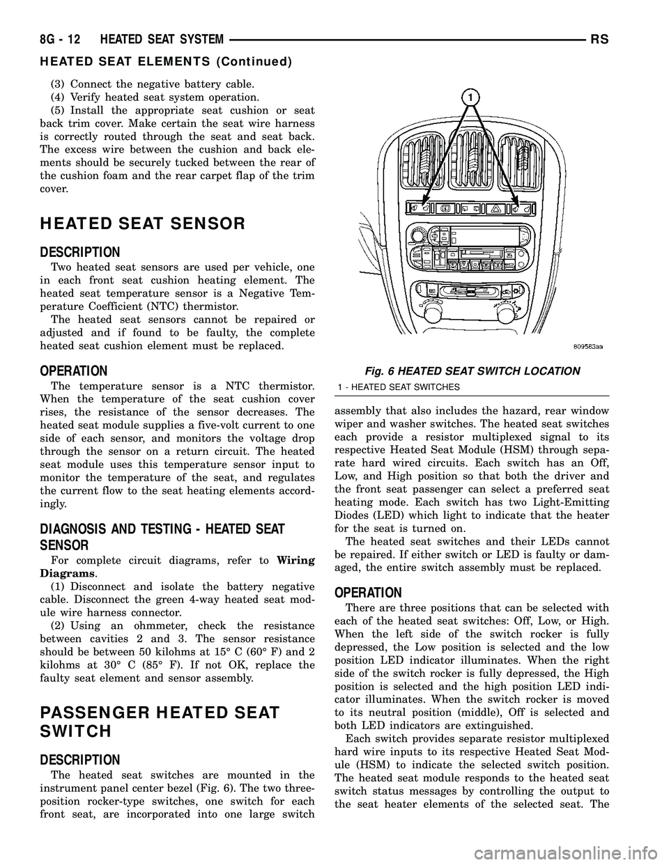
The heated seat switches are mounted in the
instrument panel center bezel (Fig. 6). The two three-
position rocker-type switches, one switch for each
front seat, are incorporated into one large switchassembly that also includes the hazard, rear window
wiper and washer switches. The heated seat switches
each provide a resistor multiplexed signal to its
respective Heated Seat Module (HSM) through sepa-
rate hard wired circuits. Each switch has an Off,
Low, and High position so that both the driver and
the front seat passenger can select a preferred seat
heating mode. Each switch has two Light-Emitting
Diodes (LED) which light to indicate that the heater
for the seat is turned on.
The heated seat switches and their LEDs cannot
be repaired. If either switch or LED is faulty or dam-
aged, the entire switch assembly must be replaced.
OPERATION
There are three positions that can be selected with
each of the heated seat switches: Off, Low, or High.
When the left side of the switch rocker is fully
depressed, the Low position is selected and the low
position LED indicator illuminates. When the right
side of the switch rocker is fully depressed, the High
position is selected and the high position LED indi-
cator illuminates. When the switch rocker is moved
to its neutral position (middle), Off is selected and
both LED indicators are extinguished.
Each switch provides separate resistor multiplexed
hard wire inputs to its respective Heated Seat Mod-
ule (HSM) to indicate the selected switch position.
The heated seat module responds to the heated seat
switch status messages by controlling the output to
the seat heater elements of the selected seat. The
Fig. 6 HEATED SEAT SWITCH LOCATION
1 - HEATED SEAT SWITCHES
8G - 12 HEATED SEAT SYSTEMRS
HEATED SEAT ELEMENTS (Continued)
Page 518 of 2585

FIRING ORDERAUTO SHUT DOWN RELAY
DESCRIPTION
The relay is located in the Power Distribution Cen-
ter (PDC). For the location of the relay within the
PDC, refer to the PDC cover for location. Check elec-
trical terminals for corrosion and repair as necessary
OPERATION
The engine switched battery (NGC vehicles)
informs the PCM when the ASD relay energizes. A 12
volt signal at this input indicates to the PCM that
the ASD has been activated. This input is also used
to power certain drivers on NGC vehicles.
When energized, the ASD relay on NGC vehicles
provides power to operate the injectors, ignition coil,
generator field, O2 sensor heaters (both upstream
and downstream), evaporative purge solenoid, EGR
solenoid (if equipped) wastegate solenoid (if
equipped), and NVLD solenoid (if equipped).
The ASD relay also provides a sense circuit to the
PCM for diagnostic purposes. If the PCM does not
receive 12 volts from this input after grounding the
control side of the ASD relay, it sets a Diagnostic
Trouble Code (DTC). The PCM energizes the ASD
any time there is an engine speed that exceeds a pre-
determined value (typically about 50 rpm). The ASD
relay can also be energized after the engine has been
turned off to perform an O2 sensor heater test, if
vehicle is equipped with OBD II diagnostics.
As mentioned earlier, the PCM energizes the ASD
relay during an O2 sensor heater test. On NGC vehi-
cles it checks the O2 heater upon vehicle start. The
PCM still operates internally to perform several
checks, including monitoring the O2 sensor heaters.
FIRING ORDER 2.4L
Firing Order 1-2-3-4-5-6 3.3/3.8L
1 - Electrical Connector
RSIGNITION CONTROL8I-3
IGNITION CONTROL (Continued)
Page 658 of 2585

(2) Turn the ignition key to the ON position. Exit
vehicle with the scan tool.
(3) After checking that no one is inside the vehicle,
connect the battery negative remote terminal.
(4) Read and record theACTIVEDiagnostic Trou-
ble Code (DTC) data.
(5) Read and record anySTOREDDTC's.
(6) Refer to the proper Body Diagnostic Procedures
manual if any DTC's are found in Step 4 and Step 5.
(7) If the airbag warning lamp either fails to light,
or goes ON and stays ON, there is a system malfunc-
tion. To test the airbag warning lamp (bulb) opera-
tion in the cluster, refer to Electrical, Instrument
Cluster, Diagnosis and Testing - Instrument Cluster.
Refer to the proper Body Diagnostic Procedures man-
ual for any other system problems.
STANDARD PROCEDURE
STANDARD PROCEDURE - HANDLING
AIRBAGS
DEPLOYED AIRBAG
The vehicle interior may contain a very small
amount of sodium hydroxide powder, a by-product of
airbag deployment. Sodium hydroxide powder can
irritate the skin, eyes, nose and throat. Wear safety
glasses, rubber gloves, and long sleeved clothing
when cleaning any of the powder residue from the
vehicle.
If you find that the cleanup is irritating your skin,
run cool water over the affected area. Also, if you
experience nasal or throat irritation, exit the vehicle
for fresh air until the irritation ceases. If irritation
continues, see a physician.
UNDEPLOYED AIRBAG
The airbags must be stored in its original special
container until used for service. At no time should a
source of electricity be permitted near the inflator on
the back of an airbag module. When carrying or han-
dling an undeployed airbag module, the trim side of
the airbag should be pointing away from the body to
minimize possibility of injury if accidental deploy-
ment occurs. Do not place undeployed airbag face
down on a solid surface, the airbag will propel into
the air if accidental deployment occurs.
STANDARD PROCEDURE - SERVICE AFTER AN
AIRBAG DEPLOYMENT
DRIVER AIRBAG
After a Driver Airbag has been deployed due to a
collision, the followingMUSTbe replaced:
²Driver Airbag²Clock Spring Assembly
²Steering Wheel
²Complete Steering Column Assembly w/Lower
Steering Column Coupler
All other airbag and vehicle components should be
closely inspected following any airbag deployment,
and should be replaced when visible damage is
incurred.
PASSENGER AIRBAG
After a Passenger Airbag has been deployed due to
a collision. the followingMUSTbe replaced:
²Passenger Airbag
²Instrument Panel and Pad Assembly
All other airbag and vehicle components should be
closely inspected following any airbag deployment,
and should be replaced when visible damage is
incurred.
SEAT AIRBAG
After a Seat Airbag has been deployed due to a col-
lision. the followingMUSTbe replaced:
²Complete Seat Back Assembly
All other airbag and vehicle components should be
closely inspected following any airbag deployment,
and should be replaced when visible damage is
incurred.
SEAT BELTS AND TENSIONERS
After a frontal impact where an airbag has been
deployed due to a collision. the followingMUSTbe
replaced:
²Front Seat Belt Buckle (driver and passenger)
with integral Tensioners.
All other seat belts should be closely inspected for
cuts, tears, fraying, or damage in any way following
any frontal impact or airbag deployment. The other
seat belts are to be replaced when visible damage is
incurred. Inspect the Lower Anchors and Tether for
CHildren (LATCH) child restraint anchors for dam-
age after an impact event and replace as needed.
CLEAN UP PROCEDURE
Roll or fold the airbag towards its mounting point
(i.e. instrument panel, steering wheel, or seat back).
Then tape the ripped cover over the deployed airbag
if applicable.
Use a vacuum cleaner to remove any residual pow-
der from the vehicle interior. Work from the outside
in to avoid kneeling or sitting in a contaminated
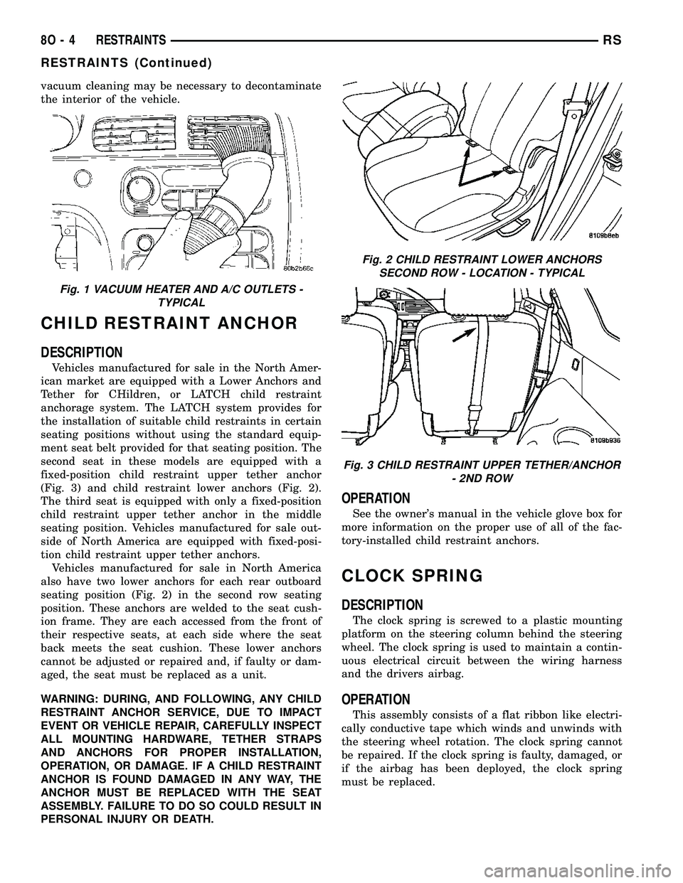
area. Vacuum the heater and A/C outlets as well (Fig.
1). If the heater or air conditioner was in RECIRC
mode at time of airbag deployment, operate blower
motor on low speed and vacuum powder residue
expelled from the heater and A/C outlets. Multiple
RSRESTRAINTS8O-3
RESTRAINTS (Continued)
Page 659 of 2585
vacuum cleaning may be necessary to decontaminate
the interior of the vehicle.
CHILD RESTRAINT ANCHOR
DESCRIPTION
Vehicles manufactured for sale in the North Amer-
ican market are equipped with a Lower Anchors and
Tether for CHildren, or LATCH child restraint
anchorage system. The LATCH system provides for
the installation of suitable child restraints in certain
seating positions without using the standard equip-
ment seat belt provided for that seating position. The
second seat in these models are equipped with a
fixed-position child restraint upper tether anchor
(Fig. 3) and child restraint lower anchors (Fig. 2).
The third seat is equipped with only a fixed-position
child restraint upper tether anchor in the middle
seating position. Vehicles manufactured for sale out-
side of North America are equipped with fixed-posi-
tion child restraint upper tether anchors.
Vehicles manufactured for sale in North America
also have two lower anchors for each rear outboard
seating position (Fig. 2) in the second row seating
position. These anchors are welded to the seat cush-
ion frame. They are each accessed from the front of
their respective seats, at each side where the seat
back meets the seat cushion. These lower anchors
cannot be adjusted or repaired and, if faulty or dam-
aged, the seat must be replaced as a unit.
WARNING: DURING, AND FOLLOWING, ANY CHILD
RESTRAINT ANCHOR SERVICE, DUE TO IMPACT
EVENT OR VEHICLE REPAIR, CAREFULLY INSPECT
ALL MOUNTING HARDWARE, TETHER STRAPS
AND ANCHORS FOR PROPER INSTALLATION,
OPERATION, OR DAMAGE. IF A CHILD RESTRAINT
ANCHOR IS FOUND DAMAGED IN ANY WAY, THE
ANCHOR MUST BE REPLACED WITH THE SEAT
ASSEMBLY. FAILURE TO DO SO COULD RESULT IN
PERSONAL INJURY OR DEATH.
OPERATION
See the owner's manual in the vehicle glove box for
more information on the proper use of all of the fac-
tory-installed child restraint anchors.
CLOCK SPRING
DESCRIPTION
The clock spring is screwed to a plastic mounting
platform on the steering column behind the steering
wheel. The clock spring is used to maintain a contin-
uous electrical circuit between the wiring harness
and the drivers airbag.
OPERATION
This assembly consists of a flat ribbon like electri-
cally conductive tape which winds and unwinds with
the steering wheel rotation. The clock spring cannot
be repaired. If the clock spring is faulty, damaged, or
if the airbag has been deployed, the clock spring
must be replaced.
Fig. 1 VACUUM HEATER AND A/C OUTLETS -
TYPICAL
Fig. 2 CHILD RESTRAINT LOWER ANCHORS
SECOND ROW - LOCATION - TYPICAL
Fig. 3 CHILD RESTRAINT UPPER TETHER/ANCHOR
- 2ND ROW
8O - 4 RESTRAINTSRS
RESTRAINTS (Continued)
Page 671 of 2585
SEAT BELT & RETRACTOR -
SECOND ROW - RIGHT OUTBOARD
WITH REAR HVAC - LWB
REMOVAL
(1) Remove first and second row seats.
(2) Remove first row seat belt lower anchor bolt.
(3) Remove first row seat belt upper anchor bolt.
(4) Remove liftgate sill plate.
(5) Remove upper liftgate trim.
(6) Remove second seat belt lower anchor bolt.
(7) Remove second seat belt upper anchor bolt.
(8) Remove D-pillar trim cover.
(9) Disconnect speaker connector. The left side has
the speaker mounted in the D-pillar trim cover and
the right side will have the speaker mounted in the
rear of the quarter trim panel, but the connector is
accessible from the rear after the D-pillar trim is
removed.
(10) Remove quarter trim bolster.
(11) Remove quarter trim panel screws.
(12) Remove quarter trim panel.
(13) Loosen HVAC unit enough to gain access to
seat belt retractor fasteners.
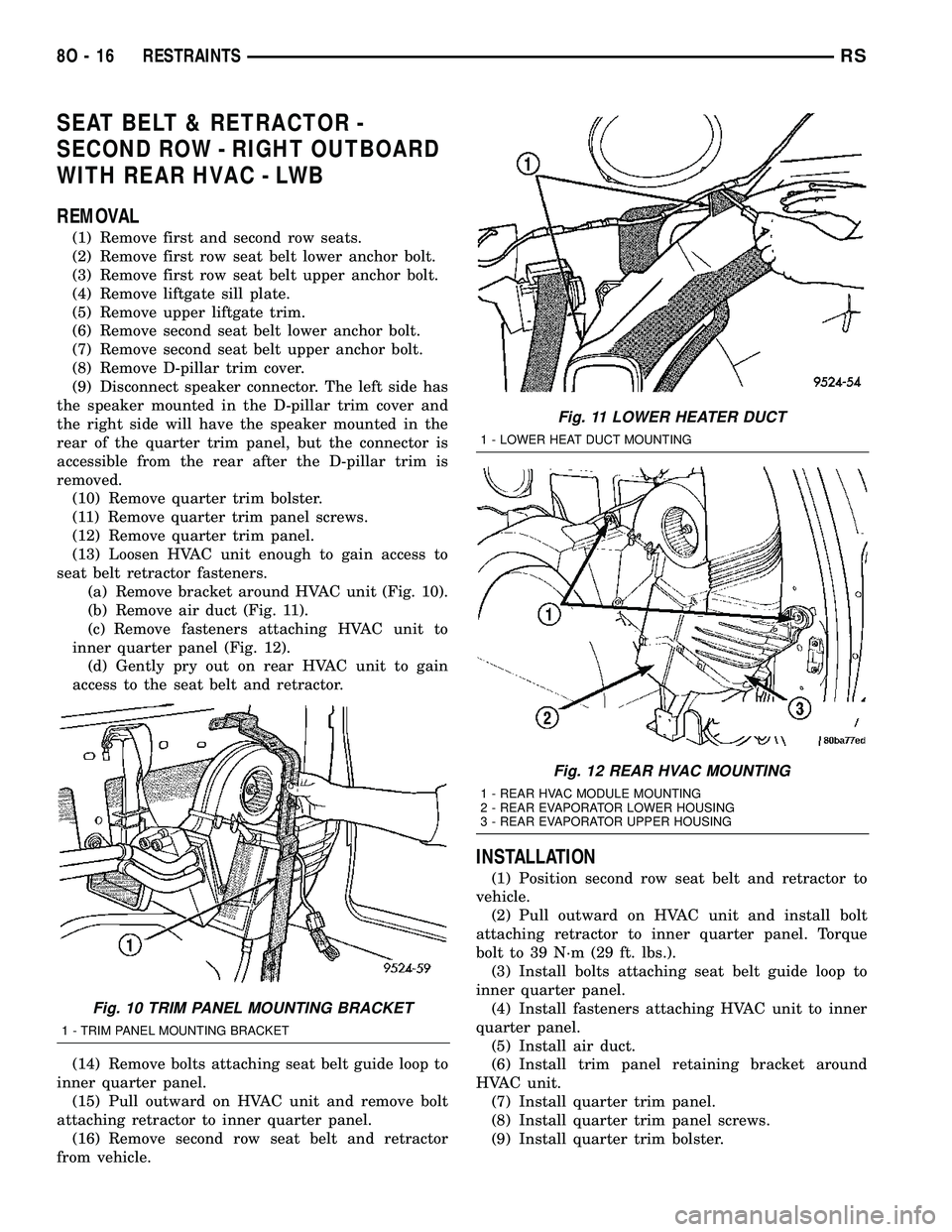
(a) Remove bracket around HVAC unit (Fig. 10).
(b) Remove air duct (Fig. 11).
(c) Remove fasteners attaching HVAC unit to
inner quarter panel (Fig. 12).
(d) Gently pry out on rear HVAC unit to gain
access to the seat belt and retractor.
(14) Remove bolts attaching seat belt guide loop to
inner quarter panel.
(15) Pull outward on HVAC unit and remove bolt
attaching retractor to inner quarter panel.
(16) Remove second row seat belt and retractor
from vehicle.
INSTALLATION
(1) Position second row seat belt and retractor to
vehicle.
(2) Pull outward on HVAC unit and install bolt
attaching retractor to inner quarter panel. Torque
bolt to 39 N´m (29 ft. lbs.).
(3) Install bolts attaching seat belt guide loop to
inner quarter panel.
(4) Install fasteners attaching HVAC unit to inner
quarter panel.
(5) Install air duct.
(6) Install trim panel retaining bracket around
HVAC unit.
(7) Install quarter trim panel.
(8) Install quarter trim panel screws.
(9) Install quarter trim bolster.
Fig. 10 TRIM PANEL MOUNTING BRACKET
1 - TRIM PANEL MOUNTING BRACKET
Fig. 11 LOWER HEATER DUCT
1 - LOWER HEAT DUCT MOUNTING
Fig. 12 REAR HVAC MOUNTING
1 - REAR HVAC MODULE MOUNTING
2 - REAR EVAPORATOR LOWER HOUSING
3 - REAR EVAPORATOR UPPER HOUSING
8O - 16 RESTRAINTSRS
Page 704 of 2585
WIRING
TABLE OF CONTENTS
page page
WIRING DIAGRAM INFORMATION....... 8W-01-1
COMPONENT INDEX.................. 8W-02-1
POWER DISTRIBUTION............... 8W-10-1
GROUND DISTRIBUTION.............. 8W-15-1
BUS COMMUNICATIONS.............. 8W-18-1
CHARGING SYSTEM.................. 8W-20-1
STARTING SYSTEM.................. 8W-21-1
FUEL/IGNITION SYSTEM.............. 8W-30-1
TRANSMISSION CONTROL SYSTEM..... 8W-31-1
VEHICLE SPEED CONTROL............ 8W-33-1
ANTILOCK BRAKES................... 8W-35-1
VEHICLE THEFT SECURITY SYSTEM..... 8W-39-1
INSTRUMENT CLUSTER............... 8W-40-1
HORN/CIGAR LIGHTER/POWER OUTLET . . 8W-41-1
AIR CONDITIONING-HEATER........... 8W-42-1
AIRBAG SYSTEM.................... 8W-43-1
INTERIOR LIGHTING.................. 8W-44-1
BODY CONTROL MODULE............. 8W-45-1
MESSAGE CENTER................... 8W-46-1AUDIO SYSTEM..................... 8W-47-1
REAR WINDOW DEFOGGER............ 8W-48-1
OVERHEAD CONSOLE................. 8W-49-1
FRONT LIGHTING.................... 8W-50-1
REAR LIGHTING..................... 8W-51-1
TURN SIGNALS...................... 8W-52-1
WIPERS............................ 8W-53-1
TRAILER TOW....................... 8W-54-1
POWER WINDOWS................... 8W-60-1
POWER DOOR LOCKS................ 8W-61-1
POWER MIRRORS................... 8W-62-1
POWER SEATS...................... 8W-63-1
POWER SUNROOF................... 8W-64-1
SPLICE INFORMATION................ 8W-70-1
CONNECTOR PIN-OUTS............... 8W-80-1
CONNECTOR/GROUND/SPLICE
LOCATION........................ 8W-91-1
POWER DISTRIBUTION SYSTEM........ 8W-97-1 RSWIRING
8W-1
Page 722 of 2585

8W-02 COMPONENT INDEX
Component Page
A/C Compressor Clutch................. 8W-42
A/C Compressor Clutch Relay............ 8W-42
A/C Pressure Sensor................... 8W-42
A/C-Heater Control.................... 8W-42
Accelerator Pedal Position Sensor......... 8W-30
Accessory Relay....................... 8W-10
Adjustable Pedals Module............... 8W-30
Adjustable Pedals Motor................ 8W-30
Adjustable Pedals Relay................ 8W-30
Adjustable Pedals Sensor............... 8W-30
Adjustable Pedals Switch............... 8W-30
Airbags............................. 8W-43
Airbag Control Module................. 8W-43
Airbag Squibs........................ 8W-43
Ambient Temperature Sensor............ 8W-49
Antenna............................ 8W-47
ATC Remote Sensor.................... 8W-42
Auto Shut Down Relay................. 8W-30
Auto Temp Control.................... 8W-42
Automatic Day/Night Mirror............. 8W-49
B-Pillar Switches...................... 8W-61
Back-Up Lamp Switch.................. 8W-51
Battery............................. 8W-20
Battery Temperature Sensor............. 8W-20
Blend Door Actuators.................. 8W-42
Blower Motors........................ 8W-42
Blower Motor Relays................... 8W-42
Blower Motor Resistor.................. 8W-42
Body Control Module................... 8W-45
Boost Pressure Sensor.................. 8W-30
Brake Fluid Level Switch............... 8W-40
Brake Lamp Switch................. 8W-30, 51
Brake Transmission Shift Interlock
Solenoid........................... 8W-31
Cabin Heater Assist................... 8W-30
Camshaft Position Sensor............... 8W-30
CD Changer......................... 8W-47
Center High Mounted Stop Lamp......... 8W-51
Cinch/Release Motors.................. 8W-61
Clockspring................. 8W-33, 41, 43, 47
Clutch Pedal Interlock Switch......... 8W-10, 30
Clutch Pedal Upstop Switch............. 8W-30
Controller Antilock Brake............... 8W-35
Crank Case Ventilation Heater........... 8W-30
Crankshaft Position Sensor.............. 8W-30
Cylinder Lock Switches................. 8W-39
Data Link Connector................... 8W-18
Defogger Relay....................... 8W-48
Door Ajar Switches.................... 8W-39
Door Courtesy Lamps.................. 8W-44
Door Lock Switches.................... 8W-61
Dosing Pump......................... 8W-30Component Page
DVD Screen.......................... 8W-47
DVD/CD Changer..................... 8W-47
ECM/PCM Relay...................... 8W-30
EGR Solenoid........................ 8W-30
Electronic Control Unit................. 8W-64
Engine Control Module................. 8W-30
Engine Coolant Temp Sensor............. 8W-30
Engine Oil Pressure Sensor.............. 8W-30
Engine Oil Pressure Switch.............. 8W-30
EVAP/Purge Solenoid.................. 8W-30
Evaporator Temperature Sensor.......... 8W-42
Floor Console Lamp................... 8W-44
Floor Console Power Outlet.............. 8W-41
Fog Lamps.......................... 8W-50
Folding Mirror Relay................... 8W-62
Front Blower Module.................. 8W-42
Front Cigar Lighter.................... 8W-41
Front Control Module.................. 8W-10
Front Fog Lamp Relay................. 8W-50
Front Reading Lamps/Switch............ 8W-44
Front Wiper High/Low Relay............. 8W-53
Front Wiper On/Off Relay............... 8W-53
Fuel Heater.......................... 8W-30
Fuel Heater Relay..................... 8W-30
Fuel Injectors........................ 8W-30
Fuel Pressure Sensor.................. 8W-30
Fuel Pressure Solenoid................. 8W-30
Fuel Pump Module.................... 8W-30
Fuel Pump Relay...................... 8W-30
Full Open Switches.................... 8W-61
Fuselink............................ 8W-10
Fuses............................... 8W-10
Generator........................... 8W-20
Glow Plug Relay...................... 8W-30
Glow Plugs.......................... 8W-30
Grounds............................ 8W-15
Headlamp Leveling Motors.............. 8W-50
Headlamp Switch..................... 8W-50
Headlamp Washer Pump Motor.......... 8W-53
Headlamp Washer Relay................ 8W-53
Headlamps.......................... 8W-50
Heated Seat Backs.................... 8W-63
Heated Seat Cushions.................. 8W-63
Heated Seat Modules.................. 8W-63
High Beam Lamps..................... 8W-50
High Note Horn....................... 8W-41
Hood Ajar Switch..................... 8W-39
Horn Relay.......................... 8W-41
Horn Switch......................... 8W-41
Idle Air Control Motor.................. 8W-30
Ignition Coil......................... 8W-30
Ignition Switch....................... 8W-10
RS8W-02 COMPONENT INDEX8W-02-1
Page 723 of 2585
Component Page
Impact Sensors....................... 8W-43
Inlet Air Temperature Sensor............ 8W-30
Instrument Cluster.................... 8W-40
Instrument Panel Switch
Bank.................. 8W-43, 44, 52, 53, 63
Integrated Power Module............... 8W-10
Intrusion Sensors..................... 8W-39
Knock Sensor........................ 8W-30
Lamp Assemblies...................... 8W-51
License Lamp..................... 8W-51, 61
Lift Pump Motor...................... 8W-30
Lift Pump Relay...................... 8W-30
Liftgate Ajar Switch................ 8W-39, 61
Liftgate Cinch/Release Motor............ 8W-61
Liftgate Flood Lamps.................. 8W-44
Liftgate Pinch Sensors................. 8W-61
Low Beam Lamps..................... 8W-50
Low Note Horn....................... 8W-41
Manifold Absolute Pressure Sensor........ 8W-30
Mass Air Flow Sensor.................. 8W-30
Memory Seat/Mirror Module.......... 8W-62, 63
Memory Set Switch.................... 8W-63
Message Center....................... 8W-46
Mid Reading Lamps................... 8W-44
Mode Door Actuator................... 8W-42
Multi-Function Switch............ 8W-50, 52, 53
Name Brand Speaker Relay............. 8W-47
Natural Vacuum Leak Detection Assembly . . 8W-30
Overhead Console..................... 8W-49
Oxygen Sensors....................... 8W-30
Park Lamp Relay..................... 8W-10
Park Lamps.......................... 8W-50
Park/Turn Signal Lamps................ 8W-50
Parking Brake Switch.................. 8W-40
Power Folding Mirror Switch............ 8W-62
Power Liftgate Module................. 8W-61
Power Liftgate Motor.................. 8W-61
Power Mirror Switch................... 8W-62
Power Mirrors........................ 8W-62
Power Outlet......................... 8W-41
Power Seat Circuit Breaker.............. 8W-10
Power Seat Motors.................... 8W-63
Power Seat Position Sensors............. 8W-63
Power Seat Switches................... 8W-63
Power Window Circuit Breaker........... 8W-10
Power Window Motors.................. 8W-60
Power Window Switches................ 8W-60
Powertrain Control Module.............. 8W-30
PTCs............................... 8W-10
Radiator Fan Relays................... 8W-42
Radiator Fans........................ 8W-42
Radio............................... 8W-47
Reading Lamps....................... 8W-44Component Page
Rear A/C-Heater Unit.................. 8W-42
Rear Auto Temp Control Switch.......... 8W-42
Rear Blower Front Control Switch........ 8W-42
Rear Blower Motor Power Module......... 8W-42
Rear Blower Rear Control Switch......... 8W-42
Rear Dome Lamp..................... 8W-44
Rear Mode Motor..................... 8W-42
Rear Power Outlet..................... 8W-41
Rear Temperature Motor................ 8W-42
Rear Window Defogger Grid............. 8W-48
Rear Wiper Motor..................... 8W-53
Rear Wiper/Washer Indicator............ 8W-53
Rear Wiper/Washer Switch.............. 8W-53
Recirculation Door Actuator............. 8W-42
Remote Keyless Entry Antenna........ 8W-39, 61
Remote Radio Switches................. 8W-47
Repeater Lamps...................... 8W-52
Seat Belt Switch...................... 8W-43
Seat Belt Tensioners................... 8W-43
Sentry Key Remote Entry Module...... 8W-39, 61
Siren............................... 8W-39
Sliding Door Control Modules............ 8W-61
Sliding Door Latch Sensing Switches...... 8W-61
Sliding Door Lock Motor/Ajar Switches..... 8W-61
Sliding Door Lock Motors............... 8W-61
Sliding Door Motors................... 8W-61
Speakers............................ 8W-47
Speed Control Servo................... 8W-33
Speed Control Switches................. 8W-33
Speed Sensors........................ 8W-31
Splices.............................. 8W-70
Starter Motor........................ 8W-21
Starter Motor Relay................... 8W-21
Sunroof Module....................... 8W-64
Sunroof Switch....................... 8W-64
Thatcham Alarm Indicator.............. 8W-39
Thatcham Alarm Module................ 8W-39
Throttle Position Sensor................ 8W-30
Traction Control Switch................. 8W-35
Trailer Tow Connector.................. 8W-54
Transmission Control Relay............. 8W-31
Transmission Range Sensor.............. 8W-31
Transmission Solenoid/Pressure Switch
Assembly.......................... 8W-31
Turn Signal Lamps.................... 8W-52
Vehicle Speed Sensor................... 8W-30
Vent Motors.......................... 8W-60
Visor/Vanity Lamps.................... 8W-44
Washer Fluid Level Switch.............. 8W-53
Washer Pump Motor................... 8W-53
Water In Fuel Sensor.................. 8W-30
Wheel Speed Sensors................... 8W-35
Wiper Module........................ 8W-53
8W - 02 - 2 8W-02 COMPONENT INDEXRS