heater CHRYSLER VOYAGER 2004 User Guide
[x] Cancel search | Manufacturer: CHRYSLER, Model Year: 2004, Model line: VOYAGER, Model: CHRYSLER VOYAGER 2004Pages: 2585, PDF Size: 62.54 MB
Page 358 of 2585

(3) With heater seated, tighten center screw
securely to assure a positive seal.
(4) Install power cord plug to heater.
(5) Fill cooling system with coolant to the proper
level. (Refer to 7 - COOLING - STANDARD PROCE-
DURE)
ENGINE COOLANT
TEMPERATURE SENSOR - 2.4L
DESCRIPTION
The engine coolant temperature sensor threads
into the top of the thermostat housing (Fig. 3). New
sensors have sealant applied to the threads.
REMOVAL
WARNING: HOT, PRESSURIZED COOLANT CAN
CAUSE INJURY BY SCALDING. COOLING SYSTEM
MUST BE PARTIALLY DRAINED BEFORE REMOV-
ING THE COOLANT TEMPERATURE SENSOR.
(1) Drain the cooling system below thermostat
level. (Refer to 7 - COOLING - STANDARD PROCE-
DURE)
(2) Disconnect coolant temperature sensor electri-
cal connector.
(3) Remove coolant temperature sensor (Fig. 3).
INSTALLATION
(1) Install coolant temperature sensor (Fig. 3).
Tighten sensor to 7 N´m (60 in. lbs.).
(2) Connect electrical connector to sensor.
(3) Fill cooling system. (Refer to 7 - COOLING -
STANDARD PROCEDURE)
ENGINE COOLANT
TEMPERATURE SENSOR -
3.3/3.8L
DESCRIPTION
The engine coolant temperature sensor threads
into a coolant passage on lower intake manifold near
the thermostat (Fig. 6). New sensors have sealant
applied to the threads.
REMOVAL
WARNING: HOT, PRESSURIZED COOLANT CAN
CAUSE INJURY BY SCALDING. COOLING SYSTEM
MUST BE PARTIALLY DRAINED BEFORE REMOV-
ING THE COOLANT TEMPERATURE SENSOR.
(1) Drain cooling system below engine coolant tem-
perature sensor level. (Refer to 7 - COOLING -
STANDARD PROCEDURE)
(2) Remove power steering reservoir and relocate
(Fig. 4). Do not disconnect hoses.
Fig. 3 Engine Coolant Temperature Sensor - 2.4L
1 - MAP SENSOR
2 - COOLANT TEMPERATURE SENSORFig. 4 Power Steering Fluid Reservoir
1 - POWER STEERING RESERVOIR
2 - BOLT - RESERVOIR TO MANIFOLD
3 - NUT - RESERVOIR TO COIL BRACKET
RSENGINE7-21
ENGINE BLOCK HEATER (Continued)
Page 359 of 2585
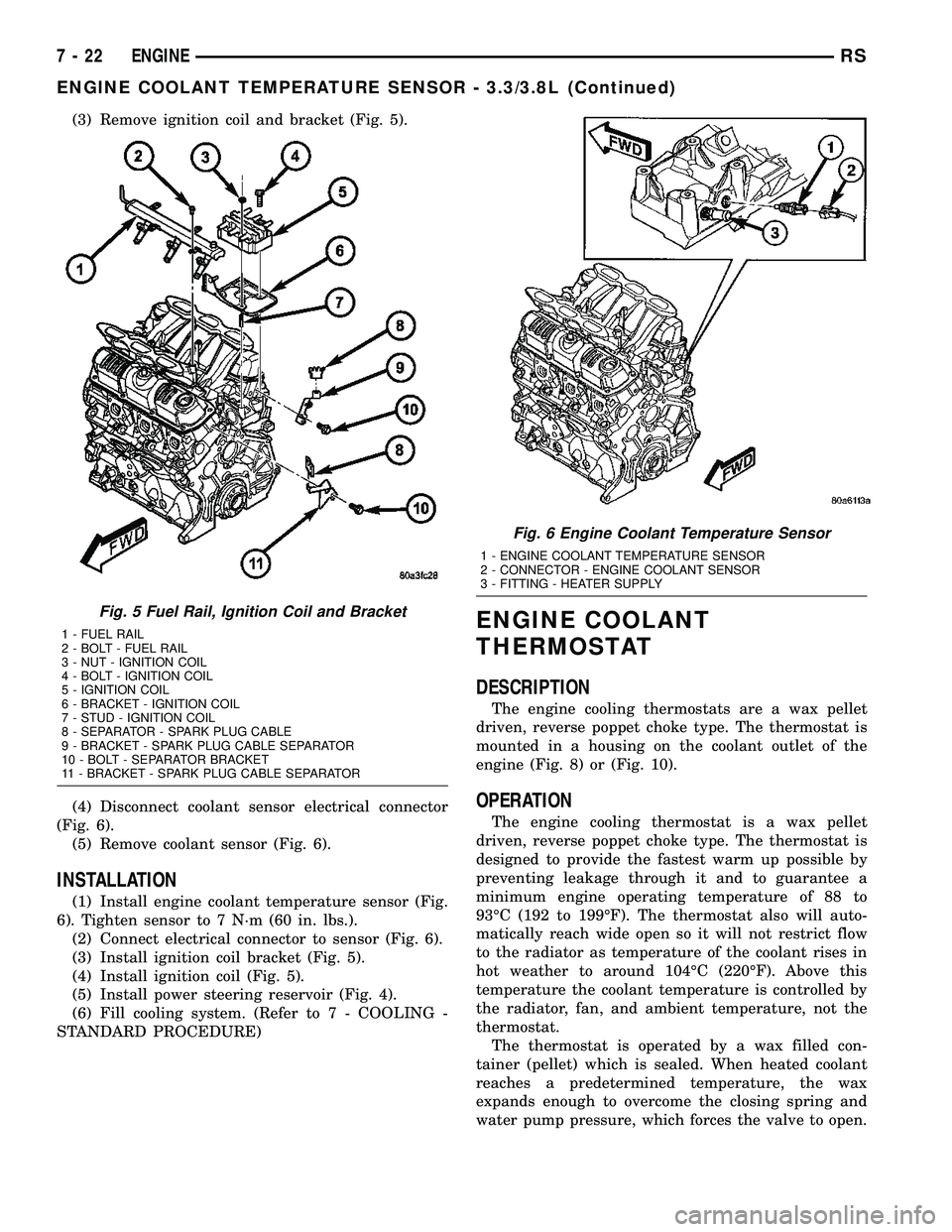
(3) Remove ignition coil and bracket (Fig. 5).
(4) Disconnect coolant sensor electrical connector
(Fig. 6).
(5) Remove coolant sensor (Fig. 6).
INSTALLATION
(1) Install engine coolant temperature sensor (Fig.
6). Tighten sensor to 7 N´m (60 in. lbs.).
(2) Connect electrical connector to sensor (Fig. 6).
(3) Install ignition coil bracket (Fig. 5).
(4) Install ignition coil (Fig. 5).
(5) Install power steering reservoir (Fig. 4).
(6) Fill cooling system. (Refer to 7 - COOLING -
STANDARD PROCEDURE)
ENGINE COOLANT
THERMOSTAT
DESCRIPTION
The engine cooling thermostats are a wax pellet
driven, reverse poppet choke type. The thermostat is
mounted in a housing on the coolant outlet of the
engine (Fig. 8) or (Fig. 10).
OPERATION
The engine cooling thermostat is a wax pellet
driven, reverse poppet choke type. The thermostat is
designed to provide the fastest warm up possible by
preventing leakage through it and to guarantee a
minimum engine operating temperature of 88 to
93ÉC (192 to 199ÉF). The thermostat also will auto-
matically reach wide open so it will not restrict flow
to the radiator as temperature of the coolant rises in
hot weather to around 104ÉC (220ÉF). Above this
temperature the coolant temperature is controlled by
the radiator, fan, and ambient temperature, not the
thermostat.
The thermostat is operated by a wax filled con-
tainer (pellet) which is sealed. When heated coolant
reaches a predetermined temperature, the wax
expands enough to overcome the closing spring and
water pump pressure, which forces the valve to open.
Fig. 5 Fuel Rail, Ignition Coil and Bracket
1 - FUEL RAIL
2 - BOLT - FUEL RAIL
3 - NUT - IGNITION COIL
4 - BOLT - IGNITION COIL
5 - IGNITION COIL
6 - BRACKET - IGNITION COIL
7 - STUD - IGNITION COIL
8 - SEPARATOR - SPARK PLUG CABLE
9 - BRACKET - SPARK PLUG CABLE SEPARATOR
10 - BOLT - SEPARATOR BRACKET
11 - BRACKET - SPARK PLUG CABLE SEPARATOR
Fig. 6 Engine Coolant Temperature Sensor
1 - ENGINE COOLANT TEMPERATURE SENSOR
2 - CONNECTOR - ENGINE COOLANT SENSOR
3 - FITTING - HEATER SUPPLY
7 - 22 ENGINERS
ENGINE COOLANT TEMPERATURE SENSOR - 3.3/3.8L (Continued)
Page 360 of 2585
DIAGNOSIS AND TESTING - ENGINE COOLANT
THERMOSTAT
The thermostat is operated by a wax filled cham-
ber (pellet) which is sealed. When heated coolant
reaches a predetermined temperature the wax pellet
expands enough to overcome the closing spring and
water pump pressure, which forces the valve to open.
Coolant leakage into the pellet will cause a thermo-
stat to fail open. Do not attempt to free up a thermo-
stat with a screwdriver.
Thermostat diagnostics is included in powertrain
control module's (PCM) programing for on-board
diagnosis. The malfunction indicator light (MIL) will
illuminate and a diagnostic trouble code (DTC) will
be set when an ªopen too soonº condition occurs. Do
not change a thermostat for lack of heater perfor-
mance or temperature gauge position, unless a DTC
is present. For other probable causes, (Refer to 7 -
COOLING/ENGINE - DIAGNOSIS AND TESTING).
Thermostat failing shut is the normal long term
mode of failure, and normally, only on high mileage
vehicles. The temperature gauge will indicate this
(Refer to 7 - COOLING/ENGINE - DIAGNOSIS AND
TESTING).
ENGINE COOLANT
THERMOSTAT - 2.4L
REMOVAL
(1) Drain cooling system below the thermostat
level. (Refer to 7 - COOLING - STANDARD PROCE-
DURE)
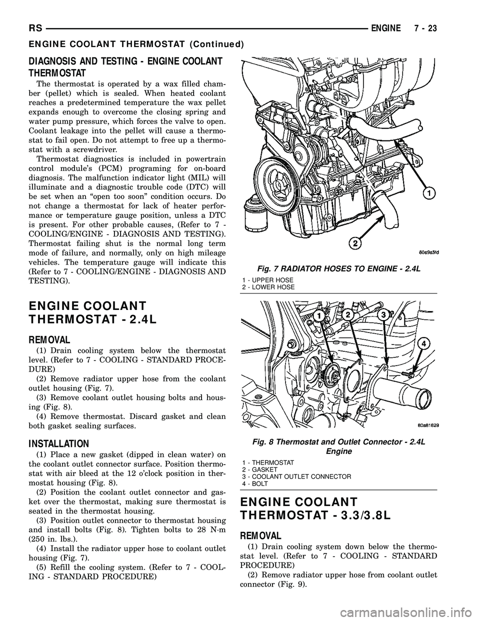
(2) Remove radiator upper hose from the coolant
outlet housing (Fig. 7).
(3) Remove coolant outlet housing bolts and hous-
ing (Fig. 8).
(4) Remove thermostat. Discard gasket and clean
both gasket sealing surfaces.
INSTALLATION
(1) Place a new gasket (dipped in clean water) on
the coolant outlet connector surface. Position thermo-
stat with air bleed at the 12 o'clock position in ther-
mostat housing (Fig. 8).
(2) Position the coolant outlet connector and gas-
ket over the thermostat, making sure thermostat is
seated in the thermostat housing.
(3) Position outlet connector to thermostat housing
and install bolts (Fig. 8). Tighten bolts to 28 N´m
(250 in. lbs.).
(4) Install the radiator upper hose to coolant outlet
housing (Fig. 7).
(5) Refill the cooling system. (Refer to 7 - COOL-
ING - STANDARD PROCEDURE)
ENGINE COOLANT
THERMOSTAT - 3.3/3.8L
REMOVAL
(1) Drain cooling system down below the thermo-
stat level. (Refer to 7 - COOLING - STANDARD
PROCEDURE)
(2) Remove radiator upper hose from coolant outlet
connector (Fig. 9).
Fig. 7 RADIATOR HOSES TO ENGINE - 2.4L
1 - UPPER HOSE
2 - LOWER HOSE
Fig. 8 Thermostat and Outlet Connector - 2.4L
Engine
1 - THERMOSTAT
2 - GASKET
3 - COOLANT OUTLET CONNECTOR
4 - BOLT
RSENGINE7-23
ENGINE COOLANT THERMOSTAT (Continued)
Page 372 of 2585
(2) Position the water pump pulley loosely between
pump housing and drive hub (Fig. 28).
(3) Install water pump and pulley to the timing
chain case cover (Fig. 27). Tighten water pump bolts
to 12 N´m (105 in. lbs.).
(4) Position pulley on water pump hub. Install
bolts and tighten to 28 N´m (250 in. lbs.) (Fig. 27).
(5) Rotate pump by hand to check for freedom of
movement.
(6) Install the accessory drive belt. (Refer to 7 -
COOLING/ACCESSORY DRIVE/DRIVE BELTS -
INSTALLATION)
(7) Install drive belt shield.
(8) Fill the cooling system. (Refer to 7 - COOLING
- STANDARD PROCEDURE)
WATER PUMP INLET TUBE -
2.4L
DESCRIPTION
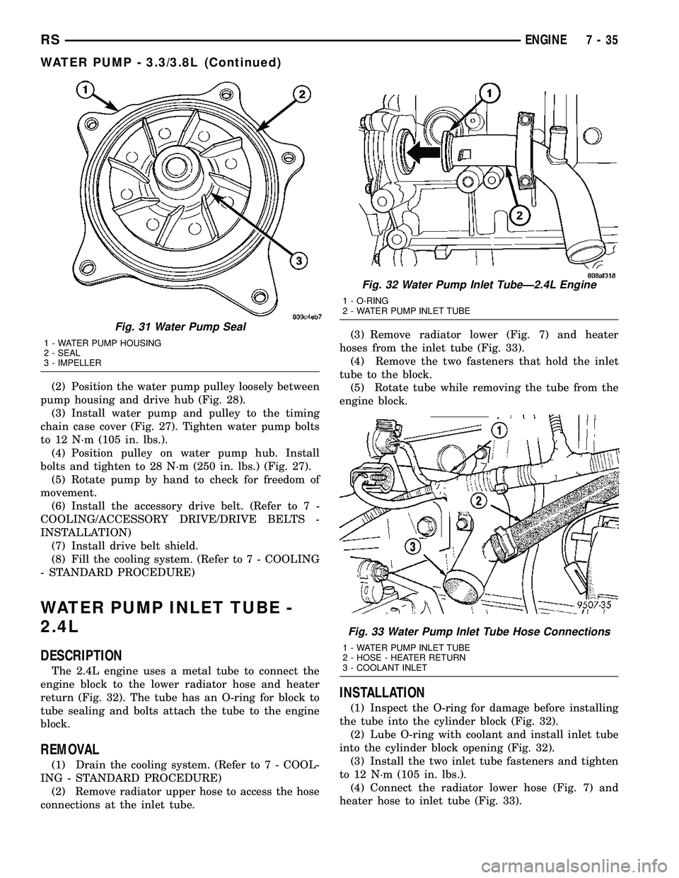
The 2.4L engine uses a metal tube to connect the
engine block to the lower radiator hose and heater
return (Fig. 32). The tube has an O-ring for block to
tube sealing and bolts attach the tube to the engine
block.
REMOVAL
(1) Drain the cooling system. (Refer to 7 - COOL-
ING - STANDARD PROCEDURE)
(2) Remove radiator upper hose to access the hose
connections at the inlet tube.(3) Remove radiator lower (Fig. 7) and heater
hoses from the inlet tube (Fig. 33).
(4) Remove the two fasteners that hold the inlet
tube to the block.
(5) Rotate tube while removing the tube from the
engine block.
INSTALLATION
(1) Inspect the O-ring for damage before installing
the tube into the cylinder block (Fig. 32).
(2) Lube O-ring with coolant and install inlet tube
into the cylinder block opening (Fig. 32).
(3) Install the two inlet tube fasteners and tighten
to 12 N´m (105 in. lbs.).
(4) Connect the radiator lower hose (Fig. 7) and
heater hose to inlet tube (Fig. 33).
Fig. 31 Water Pump Seal
1 - WATER PUMP HOUSING
2 - SEAL
3 - IMPELLER
Fig. 32 Water Pump Inlet TubeÐ2.4L Engine
1 - O-RING
2 - WATER PUMP INLET TUBE
Fig. 33 Water Pump Inlet Tube Hose Connections
1 - WATER PUMP INLET TUBE
2 - HOSE - HEATER RETURN
3 - COOLANT INLET
RSENGINE7-35
WATER PUMP - 3.3/3.8L (Continued)
Page 373 of 2585
(5) Install the radiator upper hose.
(6) Fill the cooling system. (Refer to 7 - COOLING
- STANDARD PROCEDURE)
WATER PUMP INLET TUBE -
3.3/3.8L
REMOVAL
(1) Drain the cooling system. (Refer to 7 - COOL-
ING - STANDARD PROCEDURE)
(2) Raise vehicle on hoist and remove the belt
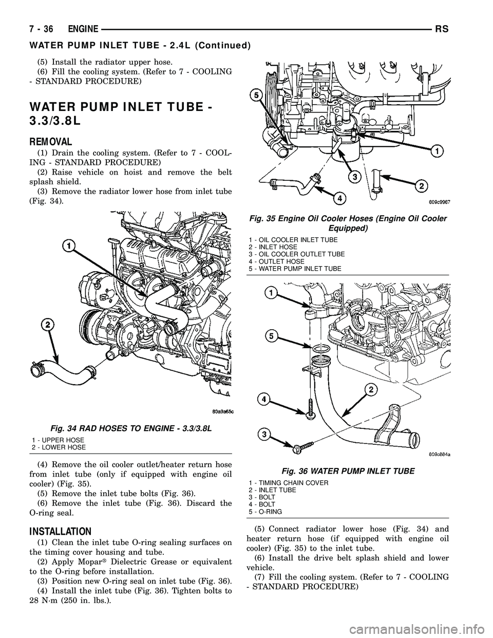
splash shield.
(3) Remove the radiator lower hose from inlet tube
(Fig. 34).
(4) Remove the oil cooler outlet/heater return hose
from inlet tube (only if equipped with engine oil
cooler) (Fig. 35).
(5) Remove the inlet tube bolts (Fig. 36).
(6) Remove the inlet tube (Fig. 36). Discard the
O-ring seal.
INSTALLATION
(1) Clean the inlet tube O-ring sealing surfaces on
the timing cover housing and tube.
(2) Apply MopartDielectric Grease or equivalent
to the O-ring before installation.
(3) Position new O-ring seal on inlet tube (Fig. 36).
(4) Install the inlet tube (Fig. 36). Tighten bolts to
28 N´m (250 in. lbs.).(5) Connect radiator lower hose (Fig. 34) and
heater return hose (if equipped with engine oil
cooler) (Fig. 35) to the inlet tube.
(6) Install the drive belt splash shield and lower
vehicle.
(7) Fill the cooling system. (Refer to 7 - COOLING
- STANDARD PROCEDURE)
Fig. 34 RAD HOSES TO ENGINE - 3.3/3.8L
1 - UPPER HOSE
2 - LOWER HOSE
Fig. 35 Engine Oil Cooler Hoses (Engine Oil Cooler
Equipped)
1 - OIL COOLER INLET TUBE
2 - INLET HOSE
3 - OIL COOLER OUTLET TUBE
4 - OUTLET HOSE
5 - WATER PUMP INLET TUBE
Fig. 36 WATER PUMP INLET TUBE
1 - TIMING CHAIN COVER
2 - INLET TUBE
3 - BOLT
4 - BOLT
5 - O-RING
7 - 36 ENGINERS
WATER PUMP INLET TUBE - 2.4L (Continued)
Page 400 of 2585
OPERATION
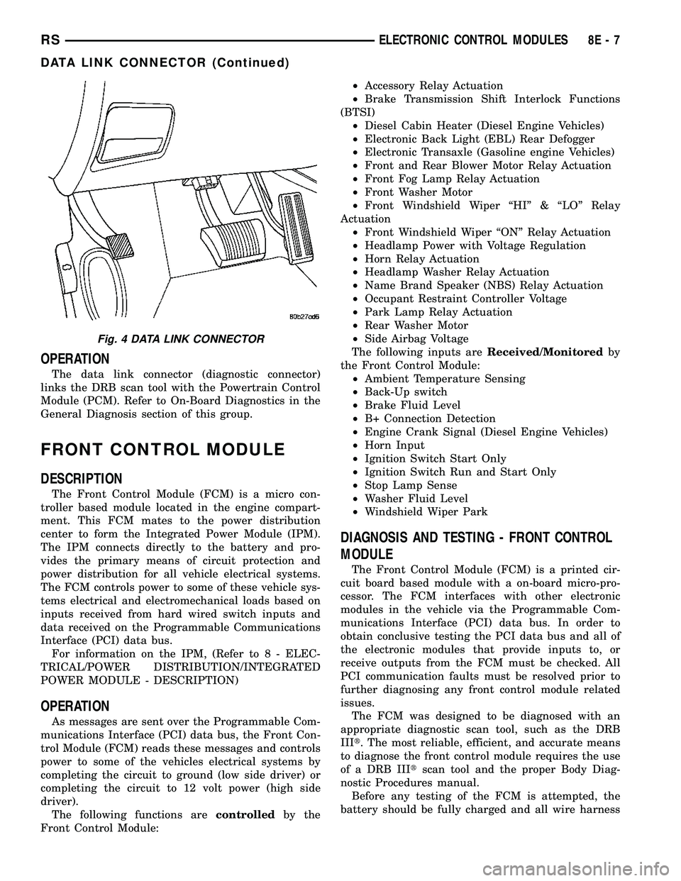
The data link connector (diagnostic connector)
links the DRB scan tool with the Powertrain Control
Module (PCM). Refer to On-Board Diagnostics in the
General Diagnosis section of this group.
FRONT CONTROL MODULE
DESCRIPTION
The Front Control Module (FCM) is a micro con-
troller based module located in the engine compart-
ment. This FCM mates to the power distribution
center to form the Integrated Power Module (IPM).
The IPM connects directly to the battery and pro-
vides the primary means of circuit protection and
power distribution for all vehicle electrical systems.
The FCM controls power to some of these vehicle sys-
tems electrical and electromechanical loads based on
inputs received from hard wired switch inputs and
data received on the Programmable Communications
Interface (PCI) data bus.
For information on the IPM, (Refer to 8 - ELEC-
TRICAL/POWER DISTRIBUTION/INTEGRATED
POWER MODULE - DESCRIPTION)
OPERATION
As messages are sent over the Programmable Com-
munications Interface (PCI) data bus, the Front Con-
trol Module (FCM) reads these messages and controls
power to some of the vehicles electrical systems by
completing the circuit to ground (low side driver) or
completing the circuit to 12 volt power (high side
driver).
The following functions arecontrolledby the
Front Control Module:²Accessory Relay Actuation
²Brake Transmission Shift Interlock Functions
(BTSI)
²Diesel Cabin Heater (Diesel Engine Vehicles)
²Electronic Back Light (EBL) Rear Defogger
²Electronic Transaxle (Gasoline engine Vehicles)
²Front and Rear Blower Motor Relay Actuation
²Front Fog Lamp Relay Actuation
²Front Washer Motor
²Front Windshield Wiper ªHIº & ªLOº Relay
Actuation
²Front Windshield Wiper ªONº Relay Actuation
²Headlamp Power with Voltage Regulation
²Horn Relay Actuation
²Headlamp Washer Relay Actuation
²Name Brand Speaker (NBS) Relay Actuation
²Occupant Restraint Controller Voltage
²Park Lamp Relay Actuation
²Rear Washer Motor
²Side Airbag Voltage
The following inputs areReceived/Monitoredby
the Front Control Module:
²Ambient Temperature Sensing
²Back-Up switch
²Brake Fluid Level
²B+ Connection Detection
²Engine Crank Signal (Diesel Engine Vehicles)
²Horn Input
²Ignition Switch Start Only
²Ignition Switch Run and Start Only
²Stop Lamp Sense
²Washer Fluid Level
²Windshield Wiper Park
DIAGNOSIS AND TESTING - FRONT CONTROL
MODULE
The Front Control Module (FCM) is a printed cir-
cuit board based module with a on-board micro-pro-
cessor. The FCM interfaces with other electronic
modules in the vehicle via the Programmable Com-
munications Interface (PCI) data bus. In order to
obtain conclusive testing the PCI data bus and all of
the electronic modules that provide inputs to, or
receive outputs from the FCM must be checked. All
PCI communication faults must be resolved prior to
further diagnosing any front control module related
issues.
The FCM was designed to be diagnosed with an
appropriate diagnostic scan tool, such as the DRB
IIIt. The most reliable, efficient, and accurate means
to diagnose the front control module requires the use
of a DRB IIItscan tool and the proper Body Diag-
nostic Procedures manual.
Before any testing of the FCM is attempted, the
battery should be fully charged and all wire harness
Fig. 4 DATA LINK CONNECTOR
RSELECTRONIC CONTROL MODULES8E-7
DATA LINK CONNECTOR (Continued)
Page 496 of 2585
HEATED SYSTEMS
TABLE OF CONTENTS
page page
HEATED GLASS........................... 1
HEATED MIRRORS......................... 6HEATED SEAT SYSTEM..................... 7
HEATED GLASS
TABLE OF CONTENTS
page page
HEATED GLASS
DESCRIPTION..........................1
OPERATION............................2
DIAGNOSIS AND TESTING - REAR WINDOW
DEFOGGER SYSTEM...................2
REAR WINDOW DEFOGGER RELAY
DESCRIPTION..........................3
OPERATION............................3REMOVAL.............................3
INSTALLATION..........................3
REAR WINDOW DEFOGGER SWITCH
DESCRIPTION..........................4
OPERATION............................4
REAR WINDOW DEFOGGER GRID
STANDARD PROCEDURE - GRID LINE AND
TERMINAL REPAIR.....................4
HEATED GLASS
DESCRIPTION
CAUTION: Grid lines can be damaged or scraped
off with sharp instruments. Care should be taken in
cleaning glass or removing foreign materials,
decals or stickers. Normal glass cleaning solvents
or hot water used with rags or toweling is recom-
mended.
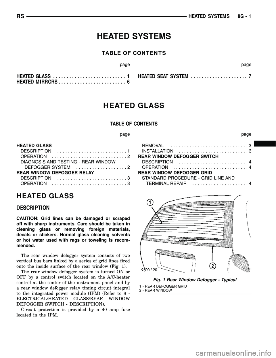
The rear window defogger system consists of two
vertical bus bars linked by a series of grid lines fired
onto the inside surface of the rear window (Fig. 1).
The rear window defogger system is turned ON or
OFF by a control switch located on the A/C-heater
control at the center of the instrument panel and by
a rear window defogger relay timing circuit integral
to the integrated power module (IPM) (Refer to 8 -
ELECTRICAL/HEATED GLASS/REAR WINDOW
DEFOGGER SWITCH - DESCRIPTION).
Circuit protection is provided by a 40 amp fuse
located in the IPM.
Fig. 1 Rear Window Defogger - Typical
1 - REAR DEFOGGER GRID
2 - REAR WINDOW
RSHEATED SYSTEMS8G-1
Page 497 of 2585
OPERATION
When the rear window defogger button is
depressed to the On position, current is directed to
the rear defogger grid lines and the heated power
mirrors (if equipped). The heated grid lines heat the
glass to help clear the rear window and side mirror
surfaces of fog or frost.
The defogger system is controlled by a momentary
switch located in the A/C-heater control on the
instrument panel. A yellow indicator in the switch
will illuminate to indicate when the defogger system
is turned on. The integrated power module (IPM)
contains the defogger system control circuitry.
NOTE:
The rear window defogger turns off automat-
ically after approximately 10 minutes of initial opera-
tion. Each following activation cycle of the defogger
system will last approximately five minutes.
The defogger system will be automatically turned
off after a programmed time interval of about ten
minutes. After the initial time interval has expired, if
the defogger switch is turned on again during the
same ignition cycle, the defogger system will auto-
matically turn off after about five minutes.
The defogger system will automatically shut off if
the ignition switch is turned to the Off position, or it
can be turned off manually by depressing the defog-
ger switch a second time.
DIAGNOSIS AND TESTING - REAR WINDOW
DEFOGGER SYSTEM
The electrically heated rear window defogger oper-
ation can be checked on the vehicle in the following
manner:
(1) Turn the ignition switch to the On position.
(2) Make sure that the defogger switch is Off.
(3) Using a ammeter on the battery, turn the rear
defogger control switch to the On position, a distinct
increase in amperage draw should be noted.
(4) The rear window defogger operation can be
checked by feeling the glass. A distinct difference in
temperature between the grid lines and adjacent
clear glass should be detected in three to four min-
utes of operation.
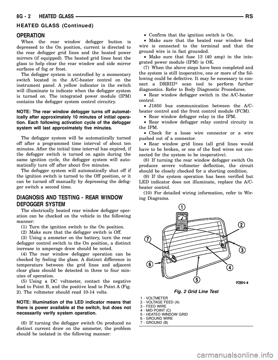
(5) Using a DC voltmeter, contact the negative
lead to Point B, and the positive lead to Point A (Fig.
2). The voltmeter should read 10-14 volts.
NOTE: Illumination of the LED indicator means that
there is power available at the switch, but does not
necessarily verify system operation.
(6) If turning the defogger switch On produced no
distinct current draw on the ammeter, the problem
should be isolated in the following manner:²Confirm that the ignition switch is On.
²Make sure that the heated rear window feed
wire is connected to the terminal and that the
ground wire is in fact grounded.
²Make sure that fuse 13 (40 amp) in the inte-
grated power module (IPM) is OK.
(7) When the above steps have been completed and
the system is still inoperative, one or more of the fol-
lowing could be defective. It may be necessary to con-
nect a DRBIIItscan tool to perform further
diagnostics. Refer to Body Diagnostic Procedures.
²Rear window defogger switch in the A/C-heater
control.
²J1850 bus communication between the A/C-
heater control and the front control module (FCM).
²Rear window defogger relay in the IPM.
²Rear window defogger relay control circuity in
the IPM.
²Check for a loose wire connector or a wire
pushed out of a connector.
²Rear window grid lines (all grid lines would
have to be broken, or one of the feed wires not con-
nected for the system to be inoperative).
(8) If turning the rear window defogger switch On
produces severe voltmeter deflection, the circuit
should be closely checked for a shorting condition.
(9) If the system operation has been verified but
LED indicator does not illuminate, replace the A/C-
heater control.
(10) For detailed wiring information, refer to Wir-
ing Diagrams.
Fig. 2 Grid Line Test
1 - VOLTMETER
2 - VOLTAGE FEED (A)
3 - FEED WIRE
4 - MID-POINT (C)
5 - HEATED WINDOW GRID
6 - GROUND WIRE
7 - GROUND (B)
8G - 2 HEATED GLASSRS
HEATED GLASS (Continued)
Page 499 of 2585
(2) Position the rear window defogger relay into
the proper receptacle in the IPM.
(3) Align the rear window defogger relay terminals
with the terminal cavities in the IPM receptacle.
(4) Push down firmly on the rear window defogger
relay until the terminals are fully seated in the ter-
minal cavities in the IPM receptacle.
(5) Install the cover onto the IPM.
(6) Reconnect the battery negative cable.
REAR WINDOW DEFOGGER
SWITCH
DESCRIPTION
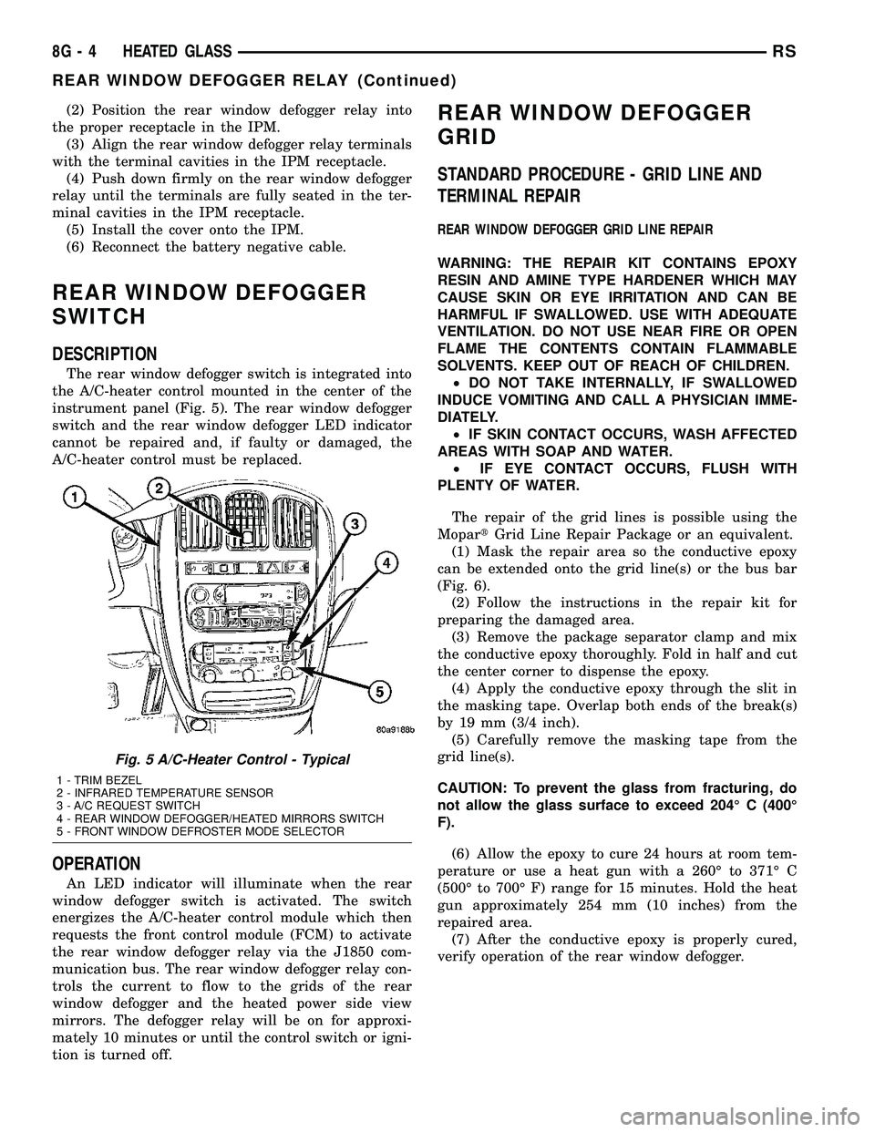
The rear window defogger switch is integrated into
the A/C-heater control mounted in the center of the
instrument panel (Fig. 5). The rear window defogger
switch and the rear window defogger LED indicator
cannot be repaired and, if faulty or damaged, the
A/C-heater control must be replaced.
OPERATION
An LED indicator will illuminate when the rear
window defogger switch is activated. The switch
energizes the A/C-heater control module which then
requests the front control module (FCM) to activate
the rear window defogger relay via the J1850 com-
munication bus. The rear window defogger relay con-
trols the current to flow to the grids of the rear
window defogger and the heated power side view
mirrors. The defogger relay will be on for approxi-
mately 10 minutes or until the control switch or igni-
tion is turned off.
REAR WINDOW DEFOGGER
GRID
STANDARD PROCEDURE - GRID LINE AND
TERMINAL REPAIR
REAR WINDOW DEFOGGER GRID LINE REPAIR
WARNING: THE REPAIR KIT CONTAINS EPOXY
RESIN AND AMINE TYPE HARDENER WHICH MAY
CAUSE SKIN OR EYE IRRITATION AND CAN BE
HARMFUL IF SWALLOWED. USE WITH ADEQUATE
VENTILATION. DO NOT USE NEAR FIRE OR OPEN
FLAME THE CONTENTS CONTAIN FLAMMABLE
SOLVENTS. KEEP OUT OF REACH OF CHILDREN.
²DO NOT TAKE INTERNALLY, IF SWALLOWED
INDUCE VOMITING AND CALL A PHYSICIAN IMME-
DIATELY.
²IF SKIN CONTACT OCCURS, WASH AFFECTED
AREAS WITH SOAP AND WATER.
²IF EYE CONTACT OCCURS, FLUSH WITH
PLENTY OF WATER.
The repair of the grid lines is possible using the
MopartGrid Line Repair Package or an equivalent.
(1) Mask the repair area so the conductive epoxy
can be extended onto the grid line(s) or the bus bar
(Fig. 6).
(2) Follow the instructions in the repair kit for
preparing the damaged area.
(3) Remove the package separator clamp and mix
the conductive epoxy thoroughly. Fold in half and cut
the center corner to dispense the epoxy.
(4) Apply the conductive epoxy through the slit in
the masking tape. Overlap both ends of the break(s)
by 19 mm (3/4 inch).
(5) Carefully remove the masking tape from the
grid line(s).
CAUTION: To prevent the glass from fracturing, do
not allow the glass surface to exceed 204É C (400É
F).
(6) Allow the epoxy to cure 24 hours at room tem-
perature or use a heat gun with a 260É to 371É C
(500É to 700É F) range for 15 minutes. Hold the heat
gun approximately 254 mm (10 inches) from the
repaired area.
(7) After the conductive epoxy is properly cured,
verify operation of the rear window defogger.
Fig. 5 A/C-Heater Control - Typical
1 - TRIM BEZEL
2 - INFRARED TEMPERATURE SENSOR
3 - A/C REQUEST SWITCH
4 - REAR WINDOW DEFOGGER/HEATED MIRRORS SWITCH
5 - FRONT WINDOW DEFROSTER MODE SELECTOR
8G - 4 HEATED GLASSRS
REAR WINDOW DEFOGGER RELAY (Continued)
Page 501 of 2585
HEATED MIRRORS
TABLE OF CONTENTS
page page
HEATED MIRRORS
DESCRIPTION..........................6OPERATION............................6
HEATED MIRRORS
DESCRIPTION
The optional heated mirror system only operates in
concert with the rear window defogger system, and
will be automatically shut off after a programmed
time interval of about ten minutes. After the initial
time interval has expired, if the defogger switch is
turned on again during the same ignition cycle, the
heated mirror system will automatically shut off
after about five minutes.
The heated mirror system will automatically shut
off if the ignition switch is turned to the Off position,
or it can be shut off manually by pressing the rear
window defogger switch a second time.
OPERATION
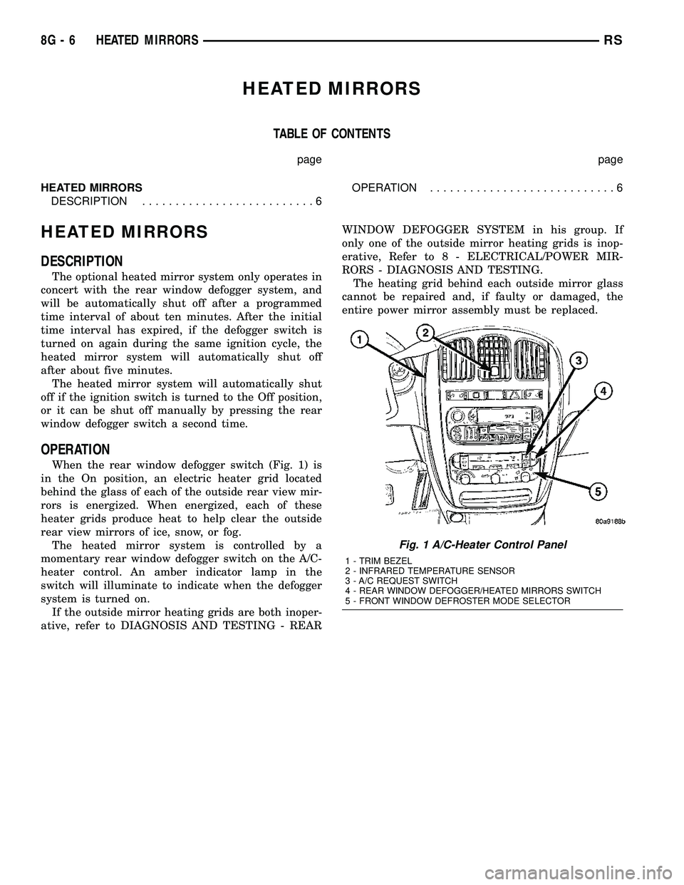
When the rear window defogger switch (Fig. 1) is
in the On position, an electric heater grid located
behind the glass of each of the outside rear view mir-
rors is energized. When energized, each of these
heater grids produce heat to help clear the outside
rear view mirrors of ice, snow, or fog.
The heated mirror system is controlled by a
momentary rear window defogger switch on the A/C-
heater control. An amber indicator lamp in the
switch will illuminate to indicate when the defogger
system is turned on.
If the outside mirror heating grids are both inoper-
ative, refer to DIAGNOSIS AND TESTING - REARWINDOW DEFOGGER SYSTEM in his group. If
only one of the outside mirror heating grids is inop-
erative, Refer to 8 - ELECTRICAL/POWER MIR-
RORS - DIAGNOSIS AND TESTING.
The heating grid behind each outside mirror glass
cannot be repaired and, if faulty or damaged, the
entire power mirror assembly must be replaced.
Fig. 1 A/C-Heater Control Panel
1 - TRIM BEZEL
2 - INFRARED TEMPERATURE SENSOR
3 - A/C REQUEST SWITCH
4 - REAR WINDOW DEFOGGER/HEATED MIRRORS SWITCH
5 - FRONT WINDOW DEFROSTER MODE SELECTOR
8G - 6 HEATED MIRRORSRS