tow CHRYSLER VOYAGER 2004 Repair Manual
[x] Cancel search | Manufacturer: CHRYSLER, Model Year: 2004, Model line: VOYAGER, Model: CHRYSLER VOYAGER 2004Pages: 2585, PDF Size: 62.54 MB
Page 629 of 2585

(3) Reconnect the power seat wire harness connec-
tor to the power seat switch connector receptacle.
(4) Position the outboard seat cushion side shield
onto the seat cushion frame
(5) Install and tighten the screws that secure the
outboard seat cushion side shield to the seat cushion
frame. Tighten the screws to 1.5 N´m (14 in. lbs.).
(6) Install the switch knobs on the switch control
levers, if equipped.
(7) Reconnect the battery negative cable.
DRIVER POWER SEAT TRACK
DESCRIPTION
The eight-way driver side power seat option
includes a electrically operated power seat track
located under the driver side front seat. The front
power seat track on the driver side of the vehicle also
provides the mounting location for the Memory Seat/
Mirror Module (MSMM). The power seat circuit
breakers are mounted on the rear of the driver side
power seat track, just behind the seat rear trim
panel. The lower half of the power seat track is
secured to the floor panel via four studs and nuts
that must be accessed from the underside of the vehi-
cle. Four bolts secure the bottom of the seat cushion
pan to the upper half of the power seat track unit.
Four additional bolts secure the seat back frame to
the power seat track unit.
The power seat track unit includes four reversible
electric motors that are secured to the upper half of
the track unit. Each motor moves the seat adjuster
through a combination of worm-drive gearboxes and
screw-type drive units. Each of the four power seat
track motors used on models equipped with the
optional memory system incorporates a position
potentiometer integral to the motor assembly, which
electronically monitors the motor position. This
enables the memory system to function by referenc-
ing the motor positions programmed into the memory
seat/mirror module.
The front and rear of the seat are operated by two
separate vertical adjustment motors. These motors
can be operated independently of each other, tilting
the entire seat assembly forward or rearward; or,
they can be operated in unison by selecting the
proper power seat switch functions, which will raise
or lower the entire seat assembly. A third motor is
the horizontal adjustment motor, which moves the
seat track in the forward and rearward directions.
The forth motor is the recliner adjustment motor,
which moves the seat back in the forward and rear-
ward directions.
The power seat track unit cannot be repaired, and
is serviced only as a complete unit. If any componentin this unit is faulty or damaged, the entire power
seat track unit must be replaced.
OPERATION
When the driver side power seat switch control
knob or knobs are actuated, a battery feed and a
ground path are applied through the switch contacts
to the power seat track or recliner adjuster motor.
The selected adjuster motor operates to move the
seat track or recliner through its drive unit in the
selected direction until the switch is released, or
until the travel limit of the adjuster is reached.
When the switch is moved in the opposite direction,
the battery feed and ground path to the motor are
reversed through the switch contacts. This causes the
adjuster motor to run in the opposite direction.
No power seat switch should be held applied in any
direction after the adjuster has reached its travel
limit. The power seat adjuster motors each contain a
self-resetting circuit breaker to protect them from
overload. However, consecutive or frequent resetting
of the circuit breaker must not be allowed to con-
tinue, or the motor may be damaged.
See the owner's manual in the vehicle glove box for
more information on the power seat switch functions
and the seat adjusting procedures.
DIAGNOSIS AND TESTING - DRIVER POWER
SEAT TRACK
WARNING: SOME VEHICLES ARE EQUIPPED WITH
SEATBACK MOUNTED AIRBAGS. BEFORE
ATTEMPTING TO DIAGNOSE OR SERVICE ANY
SEAT OR POWER SEAT SYSTEM COMPONENT
YOU MUST FIRST DISCONNECT AND ISOLATE THE
BATTERY NEGATIVE CABLE. THEN WAIT TWO MIN-
UTES FOR THE SYSTEM CAPACITOR TO DIS-
CHARGE BEFORE FURTHER SYSTEM SERVICE.
THIS IS THE ONLY SURE WAY TO DISABLE THE
AIRBAG SYSTEM. FAILURE TO DO SO COULD
RESULT IN ACCIDENTAL AIRBAG DEPLOYMENT
AND POSSIBLE PERSONAL INJURY.
Actuate the driver side power seat switch to move
all three power seat track adjusters in each direction.
The power seat track adjusters should move in each
of the selected directions. If a power seat track
adjuster fails to operate in only one direction, move
the adjuster a short distance in the opposite direction
and test again to be certain that the adjuster is not
at its travel limit. If the power seat track adjuster
still fails to operate in only one direction, refer to
Diagnosis and Testing Power Seat Switchin this
section. If the power seat track adjuster fails to oper-
ate in more than one direction, perform the following
tests. For complete circuit diagrams, refer toWiring
Diagrams.
8N - 58 POWER SEAT SYSTEMRS
PASSENGER SEAT SWITCH (Continued)
Page 631 of 2585
ward and rearward directions. The recliner adjust-
ment motor moves the seat back in the forward and
rearward directions.
The power seat track unit cannot be repaired, and
is serviced only as a complete unit. If any component
in this unit is faulty or damaged, the entire power
seat track unit must be replaced.
OPERATION
When a passenger side power seat switch control
knob or knobs are actuated, a battery feed and a
ground path are applied through the switch contacts
to the power seat track or recliner adjuster motor.
The selected adjuster motor operates to move the
seat track or recliner through its drive unit in the
selected direction until the switch is released, or
until the travel limit of the adjuster is reached.
When the switch is moved in the opposite direction,
the battery feed and ground path to the motor are
reversed through the switch contacts. This causes the
adjuster motor to run in the opposite direction.
No power seat switch should be held applied in any
direction after the adjuster has reached its travel
limit. The power seat adjuster motors each contain a
self-resetting circuit breaker to protect them from
overload. However, consecutive or frequent resetting
of the circuit breaker must not be allowed to con-
tinue, or the motor may be damaged.
See the owner's manual in the vehicle glove box for
more information on the power seat switch functions
and the seat adjusting procedures.
DIAGNOSIS AND TESTING - POWER SEAT
TRACK
WARNING: SOME VEHICLES ARE EQUIPPED WITH
SEATBACK MOUNTED AIRBAGS. BEFORE
ATTEMPTING TO DIAGNOSE OR SERVICE ANY
SEAT OR POWER SEAT SYSTEM COMPONENT
YOU MUST FIRST DISCONNECT AND ISOLATE THE
BATTERY NEGATIVE CABLE. THEN WAIT TWO MIN-
UTES FOR THE SYSTEM CAPACITOR TO DIS-
CHARGE BEFORE FURTHER SYSTEM SERVICE.
THIS IS THE ONLY SURE WAY TO DISABLE THE
AIRBAG SYSTEM. FAILURE TO DO SO COULDRESULT IN ACCIDENTAL AIRBAG DEPLOYMENT
AND POSSIBLE PERSONAL INJURY.
Actuate the passenger side power seat switch to
move the power seat track adjuster in each direction.
The power seat track adjuster should move in each of
the selected directions. If a power seat track adjuster
fails to operate in only one direction, move the
adjuster a short distance in the opposite direction
and test again to be certain that the adjuster is not
at its travel limit. If the power seat track adjuster
still fails to operate in only one direction, refer to
Diagnosis and Testing Power Seat Switchin this
section. If the power seat track adjuster fails to oper-
ate in more than one direction, perform the following
tests. For complete circuit diagrams, refer toWiring
Diagrams.
(1) Check the power seat circuit breaker under the
seat. If OK, go to Step 2. If not OK, replace the
faulty power seat circuit breaker.
(2) Check for battery voltage at the power seat cir-
cuit breaker under the seat. If OK, go to Step 3. If
not OK, repair the open fused B(+) circuit to the fuse
in the Intelligent Power Module as required.
(3) Remove the outboard seat cushion side shield
from the seat. Disconnect the seat wire harness con-
nector from the power seat switch connector recepta-
cle. Check for battery voltage at the fused B(+)
circuit cavity of the power seat wire harness connec-
tor for the power seat switch. If OK, go to Step 4. If
not OK, repair the open fused B(+) circuit to the
power seat circuit breaker under the seat as
required.
(4) Check for continuity between the ground cir-
cuit cavity of the power seat wire harness connector
for the power seat switch and a good ground. There
should be continuity. If OK, go to Step 5. If not OK,
repair the open ground circuit to ground as required.
(5) Test the power seat switch. Refer toDiagnosis
and Testing Power Seat Switchin this section. If
the switch tests OK, test the circuits of the power
seat wire harness between the inoperative power seat
track adjuster motor and the power seat switch for
shorts or opens. If the circuits check OK, replace the
faulty power seat track unit. If the circuits are not
OK, repair the power seat wire harness as required.
8N - 60 POWER SEAT SYSTEMRS
PASSENGER POWER SEAT TRACK (Continued)
Page 640 of 2585
the unlock button a second time, the remaining door
locks will unlock.If the vehicle is equipped with the memory system,
the memory message will identify which transmitter
(1 or 2) sent the signal.
ROLLING CODE
The rolling code feature changes part of the trans-
mitter message each time that it is used. The trans-
mitter message and the receiver message increment
together. Under certain conditions with a rolling code
system, such as pressing a button on the RKE trans-
mitter over 255 times outside of receiver range or
replacing the battery, the receiver and transmitter
can fall out of synchronization. To re-synchronize,
press and release the UNLOCK button on the RKE
transmitter repeatedly (it may take up to eight
cycles) while listening carefully for the power door
locks in the vehicle to cycle, indicating that resyn-
chronization has occurred. The lock function works from the RKE transmitter
even in an out of synchronization condition, therefore
it could be verified by pressing the LOCK button on
the RKE key fob.
DOOR CYLINDER LOCK
SWITCH - EXPORT
DESCRIPTION
The Door Cylinder Lock Switch (If equipped) is
used to: ² Unlock/Lock all the doors via the Central Lock-
ing feature. ² Arm/Disarm the Vehicle Theft Security System.
² Trigger the Illuminated Entry feature.
The door cylinder lock switch is mounted to the
rear of the driver door lock cylinder. When installed
on the rear of the cylinder, there is a tab on the lock
cylinder that aligns with the switch to prevent it
from turning. An anti-rotating device. The door cylin-
der lock switch is a one time use switch. Once it is
removed from the rear of the door lock cylinder, it
may not be reinstalled and a new switch must be
used.
OPERATION
When the Door Cylinder Lock Switch is turned
either way using the door key cylinder, the BCM
reads a direct message signal from the switch. If turning the key cylinder once, toward the front
of the vehicle, this will: (1) Mechanically unlock the door lock.
(2) Disarm the Vehicle Theft Security System (if
equipped). (3) Turn on the Illuminated Entry (if equipped) for
approximately 30 seconds. If the key cylinder is turned to the unlock position
(toward the front of vehicle) twice within two sec-
onds, all the doors and liftgate will unlock (if
equipped with the central locking feature). To lock the vehicle using the door cylinder lock
switch, turn the key cylinder toward the rear of the
vehicle once. This will lock the door that you are
using the key on. If equipped with the central locking
feature, this will lock all the other doors and liftgate.
Furthermore, this will arm the vehicle theft security
system and turn off the illuminated entry.
DIAGNOSIS AND TESTING - DOOR CYLINDER
LOCK SWITCH - EXPORT
Any diagnosis of the power lock system
should begin with the use of the DRB III tdiag-
nostic tool. For information on the use of the
DRB III t, refer to the appropriate Diagnostic
Service Manual. For complete circuit diagrams, refer to the appro-
priate wiring information. (1) Visually inspect the switch for proper installa-
tion. Make sure it is seated on the rear of the key
cylinder, with the tab of the door key cylinder prop-
erly aligned with the slot on the door cylinder lock
switch. (2) Disconnect the switch at the harness connector
and check the resistance in each switch position.
CAUTION: Do not disconnect the switch from the
rear of the door key cylinder. This switch is a one
time use switch. Once it is removed from the rear of
the switch, it is not reusable and must be replaced.
Test the switch at the harness connector.
DOOR CYLINDER LOCK SWITCH RESISTANCE
SWITCH POSITION RESISTANCE VALUE
COUNTERCLOCKWISE 5.4K OHMS NEUTRAL 18.4K OHMS
CLOCKWISE 2K OHMS
REMOVAL
(1) Disconnect and isolate the battery negative
cable. (2) Remove the door trim panel of the effected door
cylinder lock switch (Refer to 23 - BODY/DOOR -
FRONT/TRIM PANEL - REMOVAL). (3) Close the door window.
(4) Disconnect the door cylinder lock switch wire
connector from the door harness, and wiring clip
from the impact beam. (5) Remove the outer door handle from the door.
RS POWER LOCKS8Ns-3
POWER LOCKS (Continued)
Page 658 of 2585

(2) Turn the ignition key to the ON position. Exit
vehicle with the scan tool.
(3) After checking that no one is inside the vehicle,
connect the battery negative remote terminal.
(4) Read and record theACTIVEDiagnostic Trou-
ble Code (DTC) data.
(5) Read and record anySTOREDDTC's.
(6) Refer to the proper Body Diagnostic Procedures
manual if any DTC's are found in Step 4 and Step 5.
(7) If the airbag warning lamp either fails to light,
or goes ON and stays ON, there is a system malfunc-
tion. To test the airbag warning lamp (bulb) opera-
tion in the cluster, refer to Electrical, Instrument
Cluster, Diagnosis and Testing - Instrument Cluster.
Refer to the proper Body Diagnostic Procedures man-
ual for any other system problems.
STANDARD PROCEDURE
STANDARD PROCEDURE - HANDLING
AIRBAGS
DEPLOYED AIRBAG
The vehicle interior may contain a very small
amount of sodium hydroxide powder, a by-product of
airbag deployment. Sodium hydroxide powder can
irritate the skin, eyes, nose and throat. Wear safety
glasses, rubber gloves, and long sleeved clothing
when cleaning any of the powder residue from the
vehicle.
If you find that the cleanup is irritating your skin,
run cool water over the affected area. Also, if you
experience nasal or throat irritation, exit the vehicle
for fresh air until the irritation ceases. If irritation
continues, see a physician.
UNDEPLOYED AIRBAG
The airbags must be stored in its original special
container until used for service. At no time should a
source of electricity be permitted near the inflator on
the back of an airbag module. When carrying or han-
dling an undeployed airbag module, the trim side of
the airbag should be pointing away from the body to
minimize possibility of injury if accidental deploy-
ment occurs. Do not place undeployed airbag face
down on a solid surface, the airbag will propel into
the air if accidental deployment occurs.
STANDARD PROCEDURE - SERVICE AFTER AN
AIRBAG DEPLOYMENT
DRIVER AIRBAG
After a Driver Airbag has been deployed due to a
collision, the followingMUSTbe replaced:
²Driver Airbag²Clock Spring Assembly
²Steering Wheel
²Complete Steering Column Assembly w/Lower
Steering Column Coupler
All other airbag and vehicle components should be
closely inspected following any airbag deployment,
and should be replaced when visible damage is
incurred.
PASSENGER AIRBAG
After a Passenger Airbag has been deployed due to
a collision. the followingMUSTbe replaced:
²Passenger Airbag
²Instrument Panel and Pad Assembly
All other airbag and vehicle components should be
closely inspected following any airbag deployment,
and should be replaced when visible damage is
incurred.
SEAT AIRBAG
After a Seat Airbag has been deployed due to a col-
lision. the followingMUSTbe replaced:
²Complete Seat Back Assembly
All other airbag and vehicle components should be
closely inspected following any airbag deployment,
and should be replaced when visible damage is
incurred.
SEAT BELTS AND TENSIONERS
After a frontal impact where an airbag has been
deployed due to a collision. the followingMUSTbe
replaced:
²Front Seat Belt Buckle (driver and passenger)
with integral Tensioners.
All other seat belts should be closely inspected for
cuts, tears, fraying, or damage in any way following
any frontal impact or airbag deployment. The other
seat belts are to be replaced when visible damage is
incurred. Inspect the Lower Anchors and Tether for
CHildren (LATCH) child restraint anchors for dam-
age after an impact event and replace as needed.
CLEAN UP PROCEDURE
Roll or fold the airbag towards its mounting point
(i.e. instrument panel, steering wheel, or seat back).
Then tape the ripped cover over the deployed airbag
if applicable.
Use a vacuum cleaner to remove any residual pow-
der from the vehicle interior. Work from the outside
in to avoid kneeling or sitting in a contaminated
area. Vacuum the heater and A/C outlets as well (Fig.
1). If the heater or air conditioner was in RECIRC
mode at time of airbag deployment, operate blower
motor on low speed and vacuum powder residue
expelled from the heater and A/C outlets. Multiple
RSRESTRAINTS8O-3
RESTRAINTS (Continued)
Page 664 of 2585
OPERATION
The passenger airbag is equipped with two infla-
tors, each with three levels of pressure output. The
inflators seal the hole in the airbag cushion so it can
discharge the gas it produces directly into the cush-
ion when supplied with the proper electrical signal.
Following an airbag deployment, the airbag cushion
quickly deflates by venting this gas through the
cushion material towards the instrument panel.
The passenger airbag is secured with screws to the
instrument panel beneath the instrument panel top
pad and above the glove box opening. The instrument
panel top pad above the glove box opening conceals
the airbag door and a predetermined hinge line
beneath its decorative cover. Upon airbag deploy-
ment, the top pad will bend at the hinge line and the
door will fold back out of the way onto the top of the
instrument panel.
When the front airbag system is deployed, the fol-
lowingMUSTbe replaced:
²Complete Steering Column Assembly.
²Lower Steering Column Coupler.
²Steering Wheel.
²Clock Spring.
²Driver Airbag.
²Passenger Airbag.
²Upper Instrument Panel with Pad.
CARE OF UNDEPLOYED AIRBAGS
Airbags must be stored in their original special
container until used for service. At no time should a
source of electricity be permitted near the inflator on
the back of an airbag. When carrying or handling an
undeployed airbag, the trim side of the airbag should
be pointing away from the body to minimize possibil-
ity of injury if accidental deployment occurs. Do not
place undeployed airbag face down on a solid surface,
the airbag will propel into the air if accidental
deployment occurs.
REMOVAL
DEPLOYED AIRBAG
(1) Clean powder residue from interior of vehicle
(Refer to 8 - ELECTRICAL/RESTRAINTS - STAN-
DARD PROCEDURE - SERVICE AFTER AN AIR-
BAG DEPLOYMENT).
(2) Remove instrument panel (Refer to 23 - BODY/
INSTRUMENT PANEL/INSTRUMENT PANEL
ASSEMBLY - REMOVAL).
(3) Remove all reusable components from the
upper instrument panel and transfer to the new
instrument panel.
UNDEPLOYED AIRBAG
(1) Open hood.
(2) Disconnect and isolate the battery negative
cable.
(3) Wait two minutes for the airbag system reserve
capacitor to discharge before attempting any airbag
or instrument panel service.
(4) Remove center console bin between front seats.
(5) Remove left front door sill plate using a trim
stick (special tool #C-4755) or equivalent, and gently
prying up on sill plate.
(6) Remove left cowl panel using a trim stick or
equivalent, and gently prying out on cowl panel.
(7) Remove four screws to lower steering column
cover and remove cover.
(8) Unsnap parking brake lever from knee blocker
reinforcement.
(9) Remove Data Link Connector (DLC) from knee
blocker.
(10) Remove screws to knee blocker.
(11) Unsnap left A-pillar lower extension trim
using a trim stick or equivalent.
(12) Remove three left side instrument panel A-pil-
lar retaining bolts and loosen the instrument panel
roll down bolt.
(13) Remove four nuts at brake pedal support
bracket to instrument panel.
(14) Using a trim stick or equivalent, gently pry
off left side upper A-pillar trim.
(15) Remove six screws and two wiring connectors
to lower instrument panel cubby bin at bottom of
center stack.
(16) Remove two left side nuts at instrument panel
center stack support to floor.
(17) Remove two right side nuts at instrument
panel center stack support to floor.
(18) Remove right front door sill plate using a trim
stick or equivalent, and gently prying up on sill
plate.
(19) Remove right cowl panel using a trim stick or
equivalent, and gently prying out on cowl panel.
(20) Using a trim stick or equivalent, gently pry
out on right instrument panel end cap.
(21) Unsnap right A-pillar lower extension trim
using a trim stick or equivalent.
(22) Remove three right side instrument panel
A-pillar retaining bolts and loosen the instrument
panel roll down bolt.
(23) Using a trim stick or equivalent, gently pry
off right side upper A-pillar trim.
(24) Open glove box, pinch in sides and roll down
towards floor. With a firm pull, snap glove box door
off hinges and remove.
(25) Using a trim stick or equivalent, gently pry
up on rear of instrument panel top cover and then
pull rearward and out.
RSRESTRAINTS8O-9
PASSENGER AIRBAG (Continued)
Page 685 of 2585

(6) Rotate the SKREEM upwards and then to the
side away from the steering column to slide the
SKREEM antenna ring from around the ignition
switch lock cylinder housing.
(7) Remove the SKREEM from the vehicle.
INSTALLATION
(1) Slip the Sentry Key Remote Entry Module
(SKREEM) antenna ring around the ignition switch
lock cylinder housing. Rotate the SKREEM down-
wards and then towards the steering column.
(2) Install the one screws securing the SKREEM to
the steering column.
(3) Connect the steering column wire harness to
the SKREEM.
(4) Install the steering column upper and lower
shrouds (Refer to 19 - STEERING/COLUMN/UPPER
SHROUD - INSTALLATION) and (Refer to 19 -
STEERING/COLUMN/LOWER SHROUD - INSTAL-
LATION).
(5) Install the Steering Column Opening Cover
(Refer to 23 - BODY/INSTRUMENT PANEL/STEER-
ING COLUMN OPENING COVER - INSTALLA-
TION)
(6) Connect the battery negative cable.
TRANSPONDER KEY
DESCRIPTION
The Sentry Key Remote Entry System (SKREES)
uses a transponder chip that is integral to each igni-
tion key to communicate with the Sentry Key Remote
Entry Module (SKREEM). Ignition keys are supplied
with the vehicle when it is shipped from the factory.
The transponder chip is undermolded within the
head of the key.
OPERATION
Each Sentry Key has a unique transponder identi-
fication code permanently programmed into it by the
manufacturer. Likewise, the Sentry Key Remote
Entry Module (SKREEM) has a unique9Secret Key9
code programmed into it by the manufacturer as
well. When a Sentry Key is programmed into the
memory of the SKREEM, the SKREEM stores the
transponder identification code from the Sentry Key,
and the Sentry Key learns the9Secret Key9code from
the SKREEM. Once the Sentry Key learns the
9Secret Key9code of the SKREEM, it is also perma-
nently programmed into the transponder's memory.
Therefore, blank keys for the Sentry Key Remote
Entry System (SKREES) must be programmed by
the SKREEM in addition to being cut to match the
mechanical coding of the ignition lock cylinder. Refer
to Electrical, Vehicle Theft Security, TransponderKey, Standard Procedure - Transponder Program-
ming.
The Sentry Key's transponder is within the range
of the SKREEM's transceiver antenna ring when it is
inserted into the ignition lock cylinder. When the
ignition switch is turned to the ON position, the
SKREEM communicates with the Sentry Key via a
radio frequency (RF) signal. The SKREEM deter-
mines if a valid key is present based on the informa-
tion it receives from the Sentry Key. If a valid key is
detected, that fact is communicated to the PCM via
the PCI bus and the vehicle is allowed to continue
running. If an invalid key is received by the PCM or
no status at all is communicated, the vehicle will
stall after two (2) seconds of running. The indicator
light will be flashing at this point. The Sentry Key's
transponder can not be repaired. If it is faulty or
damaged, it must be replaced.
Common communication problems:
²Two transponder keys too close together.
²Speed Pass too close to transponder key.
Solid indicator that there is a system failure.
²Loss of PCM communication.
²Failed antenna circuit.
STANDARD PROCEDURE - TRANSPONDER
PROGRAMMING
USING A DRBIIITSCAN TOOL
All Sentry Keys included with the vehicle are pre-
programmed to work with the Sentry Key Remote
Entry System (SKREES) when it is shipped from the
factory. The Sentry Key Remote Entry Module
(SKREEM) can be programmed to recognize up to a
total of eight Sentry Keys. When programming a
blank Sentry Key transponder, the key must first be
cut to match the ignition lock cylinder of the vehicle
for which it will be used. The vehicle's four digit PIN
code will be required to complete this task since you
will need it to enter the Secured Access Mode in the
SKREEM. The following steps must be completed
using a DRBIIItscan tool:
(1) Insert the blank key into the ignition and turn
it to the RUN position.
(2) Using a DRBIIItscan tool, select9Theft
Alarm,99SKREEM,99Miscellaneous,9and then9Pro-
gram New Key.9
(3) Enter the four digit PIN code using the
DRBIIItscan tool. When programming is completed,
the SKREEM will exit Secured Access Mode and the
DRBIIItscan tool will display the results of your
attempt to program the key. One of five distinct
results may be displayed. All five are listed below:
²(Programming Successful(is displayed if the
Sentry Key programming is successful.
8Q - 6 VEHICLE THEFT SECURITYRS
SENTRY KEY REMOTE ENTRY MODULE (Continued)
Page 704 of 2585
WIRING
TABLE OF CONTENTS
page page
WIRING DIAGRAM INFORMATION....... 8W-01-1
COMPONENT INDEX.................. 8W-02-1
POWER DISTRIBUTION............... 8W-10-1
GROUND DISTRIBUTION.............. 8W-15-1
BUS COMMUNICATIONS.............. 8W-18-1
CHARGING SYSTEM.................. 8W-20-1
STARTING SYSTEM.................. 8W-21-1
FUEL/IGNITION SYSTEM.............. 8W-30-1
TRANSMISSION CONTROL SYSTEM..... 8W-31-1
VEHICLE SPEED CONTROL............ 8W-33-1
ANTILOCK BRAKES................... 8W-35-1
VEHICLE THEFT SECURITY SYSTEM..... 8W-39-1
INSTRUMENT CLUSTER............... 8W-40-1
HORN/CIGAR LIGHTER/POWER OUTLET . . 8W-41-1
AIR CONDITIONING-HEATER........... 8W-42-1
AIRBAG SYSTEM.................... 8W-43-1
INTERIOR LIGHTING.................. 8W-44-1
BODY CONTROL MODULE............. 8W-45-1
MESSAGE CENTER................... 8W-46-1AUDIO SYSTEM..................... 8W-47-1
REAR WINDOW DEFOGGER............ 8W-48-1
OVERHEAD CONSOLE................. 8W-49-1
FRONT LIGHTING.................... 8W-50-1
REAR LIGHTING..................... 8W-51-1
TURN SIGNALS...................... 8W-52-1
WIPERS............................ 8W-53-1
TRAILER TOW....................... 8W-54-1
POWER WINDOWS................... 8W-60-1
POWER DOOR LOCKS................ 8W-61-1
POWER MIRRORS................... 8W-62-1
POWER SEATS...................... 8W-63-1
POWER SUNROOF................... 8W-64-1
SPLICE INFORMATION................ 8W-70-1
CONNECTOR PIN-OUTS............... 8W-80-1
CONNECTOR/GROUND/SPLICE
LOCATION........................ 8W-91-1
POWER DISTRIBUTION SYSTEM........ 8W-97-1 RSWIRING
8W-1
Page 711 of 2585
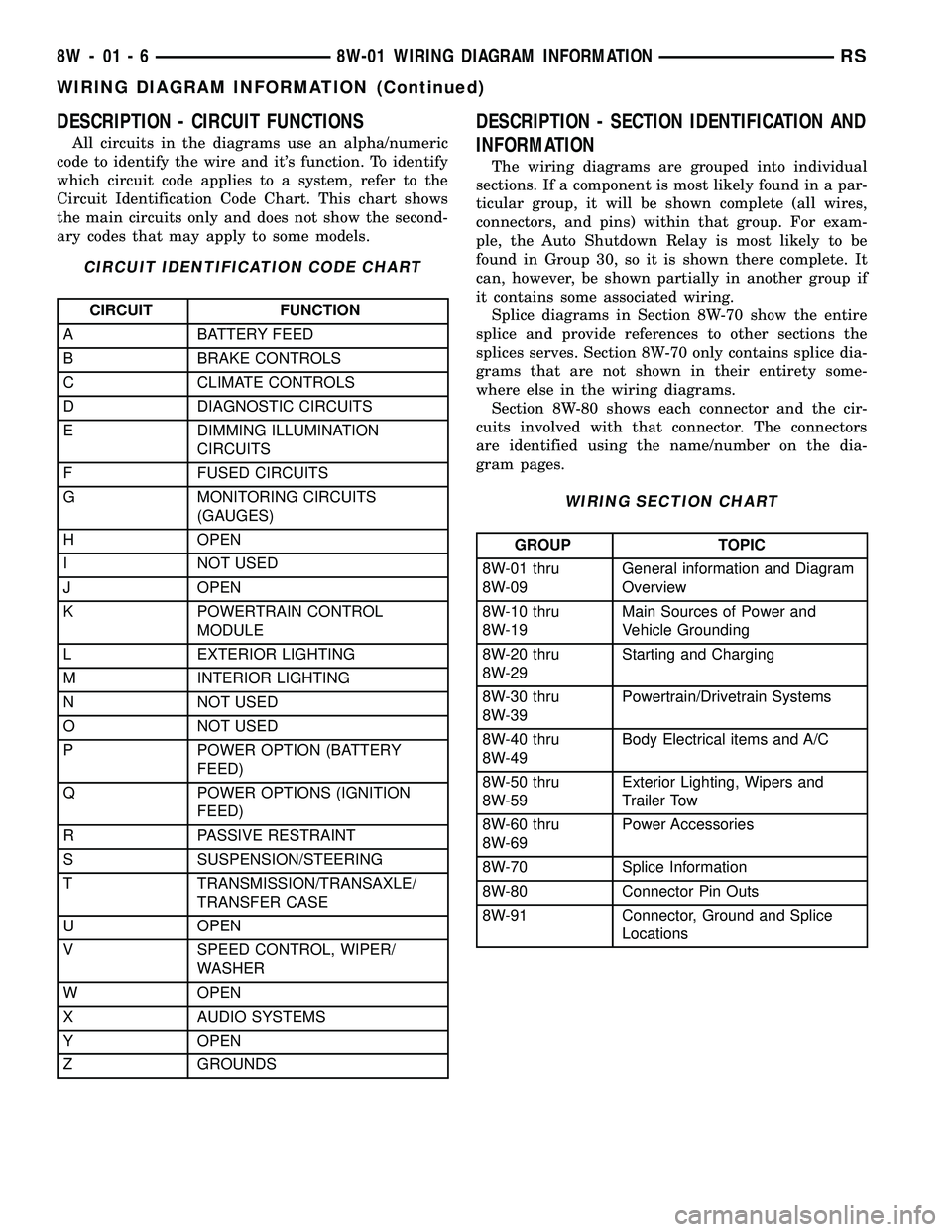
DESCRIPTION - CIRCUIT FUNCTIONS
All circuits in the diagrams use an alpha/numeric
code to identify the wire and it's function. To identify
which circuit code applies to a system, refer to the
Circuit Identification Code Chart. This chart shows
the main circuits only and does not show the second-
ary codes that may apply to some models.
CIRCUIT IDENTIFICATION CODE CHART
CIRCUIT FUNCTION
A BATTERY FEED
B BRAKE CONTROLS
C CLIMATE CONTROLS
D DIAGNOSTIC CIRCUITS
E DIMMING ILLUMINATION
CIRCUITS
F FUSED CIRCUITS
G MONITORING CIRCUITS
(GAUGES)
H OPEN
I NOT USED
J OPEN
K POWERTRAIN CONTROL
MODULE
L EXTERIOR LIGHTING
M INTERIOR LIGHTING
N NOT USED
O NOT USED
P POWER OPTION (BATTERY
FEED)
Q POWER OPTIONS (IGNITION
FEED)
R PASSIVE RESTRAINT
S SUSPENSION/STEERING
T TRANSMISSION/TRANSAXLE/
TRANSFER CASE
U OPEN
V SPEED CONTROL, WIPER/
WASHER
W OPEN
X AUDIO SYSTEMS
Y OPEN
Z GROUNDS
DESCRIPTION - SECTION IDENTIFICATION AND
INFORMATION
The wiring diagrams are grouped into individual
sections. If a component is most likely found in a par-
ticular group, it will be shown complete (all wires,
connectors, and pins) within that group. For exam-
ple, the Auto Shutdown Relay is most likely to be
found in Group 30, so it is shown there complete. It
can, however, be shown partially in another group if
it contains some associated wiring.
Splice diagrams in Section 8W-70 show the entire
splice and provide references to other sections the
splices serves. Section 8W-70 only contains splice dia-
grams that are not shown in their entirety some-
where else in the wiring diagrams.
Section 8W-80 shows each connector and the cir-
cuits involved with that connector. The connectors
are identified using the name/number on the dia-
gram pages.
WIRING SECTION CHART
GROUP TOPIC
8W-01 thru
8W-09General information and Diagram
Overview
8W-10 thru
8W-19Main Sources of Power and
Vehicle Grounding
8W-20 thru
8W-29Starting and Charging
8W-30 thru
8W-39Powertrain/Drivetrain Systems
8W-40 thru
8W-49Body Electrical items and A/C
8W-50 thru
8W-59Exterior Lighting, Wipers and
Trailer Tow
8W-60 thru
8W-69Power Accessories
8W-70 Splice Information
8W-80 Connector Pin Outs
8W-91 Connector, Ground and Splice
Locations
8W - 01 - 6 8W-01 WIRING DIAGRAM INFORMATIONRS
WIRING DIAGRAM INFORMATION (Continued)
Page 723 of 2585
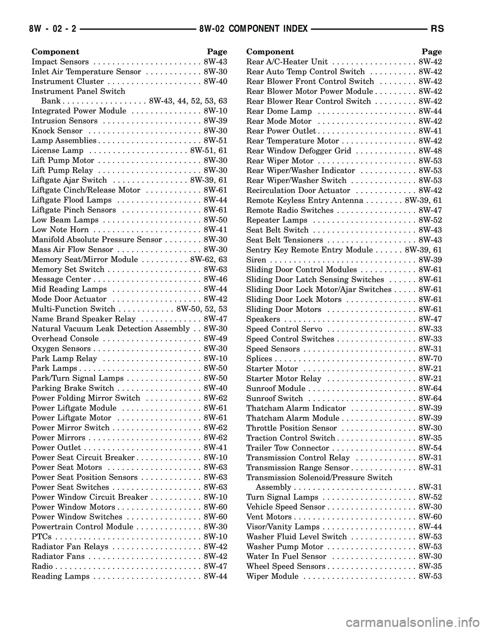
Component Page
Impact Sensors....................... 8W-43
Inlet Air Temperature Sensor............ 8W-30
Instrument Cluster.................... 8W-40
Instrument Panel Switch
Bank.................. 8W-43, 44, 52, 53, 63
Integrated Power Module............... 8W-10
Intrusion Sensors..................... 8W-39
Knock Sensor........................ 8W-30
Lamp Assemblies...................... 8W-51
License Lamp..................... 8W-51, 61
Lift Pump Motor...................... 8W-30
Lift Pump Relay...................... 8W-30
Liftgate Ajar Switch................ 8W-39, 61
Liftgate Cinch/Release Motor............ 8W-61
Liftgate Flood Lamps.................. 8W-44
Liftgate Pinch Sensors................. 8W-61
Low Beam Lamps..................... 8W-50
Low Note Horn....................... 8W-41
Manifold Absolute Pressure Sensor........ 8W-30
Mass Air Flow Sensor.................. 8W-30
Memory Seat/Mirror Module.......... 8W-62, 63
Memory Set Switch.................... 8W-63
Message Center....................... 8W-46
Mid Reading Lamps................... 8W-44
Mode Door Actuator................... 8W-42
Multi-Function Switch............ 8W-50, 52, 53
Name Brand Speaker Relay............. 8W-47
Natural Vacuum Leak Detection Assembly . . 8W-30
Overhead Console..................... 8W-49
Oxygen Sensors....................... 8W-30
Park Lamp Relay..................... 8W-10
Park Lamps.......................... 8W-50
Park/Turn Signal Lamps................ 8W-50
Parking Brake Switch.................. 8W-40
Power Folding Mirror Switch............ 8W-62
Power Liftgate Module................. 8W-61
Power Liftgate Motor.................. 8W-61
Power Mirror Switch................... 8W-62
Power Mirrors........................ 8W-62
Power Outlet......................... 8W-41
Power Seat Circuit Breaker.............. 8W-10
Power Seat Motors.................... 8W-63
Power Seat Position Sensors............. 8W-63
Power Seat Switches................... 8W-63
Power Window Circuit Breaker........... 8W-10
Power Window Motors.................. 8W-60
Power Window Switches................ 8W-60
Powertrain Control Module.............. 8W-30
PTCs............................... 8W-10
Radiator Fan Relays................... 8W-42
Radiator Fans........................ 8W-42
Radio............................... 8W-47
Reading Lamps....................... 8W-44Component Page
Rear A/C-Heater Unit.................. 8W-42
Rear Auto Temp Control Switch.......... 8W-42
Rear Blower Front Control Switch........ 8W-42
Rear Blower Motor Power Module......... 8W-42
Rear Blower Rear Control Switch......... 8W-42
Rear Dome Lamp..................... 8W-44
Rear Mode Motor..................... 8W-42
Rear Power Outlet..................... 8W-41
Rear Temperature Motor................ 8W-42
Rear Window Defogger Grid............. 8W-48
Rear Wiper Motor..................... 8W-53
Rear Wiper/Washer Indicator............ 8W-53
Rear Wiper/Washer Switch.............. 8W-53
Recirculation Door Actuator............. 8W-42
Remote Keyless Entry Antenna........ 8W-39, 61
Remote Radio Switches................. 8W-47
Repeater Lamps...................... 8W-52
Seat Belt Switch...................... 8W-43
Seat Belt Tensioners................... 8W-43
Sentry Key Remote Entry Module...... 8W-39, 61
Siren............................... 8W-39
Sliding Door Control Modules............ 8W-61
Sliding Door Latch Sensing Switches...... 8W-61
Sliding Door Lock Motor/Ajar Switches..... 8W-61
Sliding Door Lock Motors............... 8W-61
Sliding Door Motors................... 8W-61
Speakers............................ 8W-47
Speed Control Servo................... 8W-33
Speed Control Switches................. 8W-33
Speed Sensors........................ 8W-31
Splices.............................. 8W-70
Starter Motor........................ 8W-21
Starter Motor Relay................... 8W-21
Sunroof Module....................... 8W-64
Sunroof Switch....................... 8W-64
Thatcham Alarm Indicator.............. 8W-39
Thatcham Alarm Module................ 8W-39
Throttle Position Sensor................ 8W-30
Traction Control Switch................. 8W-35
Trailer Tow Connector.................. 8W-54
Transmission Control Relay............. 8W-31
Transmission Range Sensor.............. 8W-31
Transmission Solenoid/Pressure Switch
Assembly.......................... 8W-31
Turn Signal Lamps.................... 8W-52
Vehicle Speed Sensor................... 8W-30
Vent Motors.......................... 8W-60
Visor/Vanity Lamps.................... 8W-44
Washer Fluid Level Switch.............. 8W-53
Washer Pump Motor................... 8W-53
Water In Fuel Sensor.................. 8W-30
Wheel Speed Sensors................... 8W-35
Wiper Module........................ 8W-53
8W - 02 - 2 8W-02 COMPONENT INDEXRS
Page 725 of 2585

Component Page
Horn Relay.................. 8W-10-17, 35, 60
Ignition Coil....................... 8W-10-42
Ignition Switch . . . 8W-10-18, 25, 36, 37, 45, 46, 49,
54, 55, 61
Instrument Cluster............... 8W-10-25, 52
Instrument Panel Switch Bank........ 8W-10-68
Integrated Power Module....... 8W-10-3, 4, 5, 13,
15, 16, 17, 18, 19, 20, 21,
22, 23, 24, 25, 26, 27, 28,
29, 30, 31, 32, 35, 36, 37,
38, 39, 40, 41, 42, 43, 44,
45, 47, 48, 49, 50, 52, 53,
54, 55, 56, 57, 58, 59, 60,
61, 62, 63, 64, 65, 66, 67, 68
Left Door Speaker.................. 8W-10-39
Left Fog Lamp.................. 8W-10-15, 27
Left Front Park/Turn
Signal Lamp............ 8W-10-15, 28, 57, 66
Left Headlamp..................... 8W-10-58
Left Headlamp Leveling Motor . . . 8W-10-29, 63, 66
Left High Beam Lamp............... 8W-10-59
Left Low Beam Lamp................ 8W-10-59
Left Park Lamp................. 8W-10-29, 66
Left Power Mirror................... 8W-10-39
Left Rear Lamp Assembly....... 8W-10-28, 29, 66
Left Rear Speaker.................. 8W-10-39
Left Repeater Lamp................. 8W-10-52
Left Sliding Door Control Module....... 8W-10-53
Left Turn Signal Lamp............... 8W-10-57
License Lamp................ 8W-10-28, 29, 66
Lift Pump Motor................. 8W-10-23, 43
Lift Pump Relay................. 8W-10-23, 43
Low Note Horn..................... 8W-10-35
Mass Air Flow Sensor................ 8W-10-44
Memory Seat/Mirror Module.......... 8W-10-50
Message Center.................... 8W-10-52
Name Brand Speaker Relay..... 8W-10-20, 39, 60
Overhead Console................... 8W-10-40
Park Lamp Relay.......... 8W-10-15, 28, 29, 60
Passenger Folding Mirror
Relay.................. 8W-10-22, 24, 45, 48
Passenger Heated Seat Module........ 8W-10-51
Passenger Power Seat Switch.......... 8W-10-51
Passenger Power Window Switch....... 8W-10-31
Power Liftgate Module............... 8W-10-53
Power Mirror Switch........ 8W-10-22, 24, 47, 48
Power Outlet...................... 8W-10-35
Power Seat Circuit Breaker........ 8W-10-25, 50Component Page
Power Window Circuit Breaker...... 8W-10-16, 31
Power Window Switch............... 8W-10-33
Powertrain Control Module..... 8W-10-18, 21, 22,
36, 41, 42, 45, 56, 62, 63, 68
PTC4 ......................... 8W-10-20, 39
PTC7 ................... 8W-10-16, 17, 18, 35
Radiator Fan Relay............ 8W-10-26, 52, 56
Radiator Fan Relay No. 1.......... 8W-10-13, 44
Radiator Fan Relay No. 2....... 8W-10-26, 44, 52
Radiator Fan Relay No. 3............. 8W-10-44
Radio......................... 8W-10-32, 40
Rear A/C-Heater Unit............. 8W-10-19, 38
Rear Blower Motor Power Module . . . 8W-10-19, 38
Rear Blower Motor Relay.... 8W-10-19, 20, 38, 64
Rear Power Outlet............ 8W-10-16, 31, 32
Rear Window Defogger Grid........ 8W-10-20, 39
Rear Wiper Motor................... 8W-10-31
Right Door Speaker................. 8W-10-39
Right Fog Lamp................. 8W-10-15, 27
Right Front Park/Turn
Signal Lamp............ 8W-10-15, 28, 57, 61
Right Headlamp.................... 8W-10-58
Right Headlamp Leveling Motor . . 8W-10-29, 61, 63
Right High Beam Lamp.............. 8W-10-59
Right Low Beam Lamp............... 8W-10-59
Right Park Lamp................ 8W-10-29, 61
Right Power Mirror................. 8W-10-39
Right Rear Lamp
Assembly............ 8W-10-15, 28, 29, 61, 67
Right Rear Speaker................. 8W-10-39
Right Repeater Lamp................ 8W-10-52
Right Sliding Door Control Module..... 8W-10-53
Right Turn Signal Lamp.............. 8W-10-57
Sentry Key Remote Entry
Module.............. 8W-10-40, 46, 49, 54, 55
Siren............................. 8W-10-40
Starter Motor.......... 8W-10-13, 14, 18, 36, 37
Starter Motor Relay...... 8W-10-18, 36, 37, 54, 55
Sunroof Module.................. 8W-10-31, 53
Thatcham Alarm Module . . 8W-10-40, 46, 49, 55, 68
Trailer Tow Connector............ 8W-10-28, 66
Transmission Control Relay........ 8W-10-21, 41
Transmission Solenoid/Pressure Switch
Assembly....................... 8W-10-41
Vehicle Speed Sensor................ 8W-10-43
Washer Fluid Level Switch............ 8W-10-61
Washer Pump Motor................. 8W-10-68
Wiper Module................ 8W-10-16, 30, 60
8W - 10 - 2 8W-10 POWER DISTRIBUTIONRS