instrument cluster CHRYSLER VOYAGER 2004 Service Manual
[x] Cancel search | Manufacturer: CHRYSLER, Model Year: 2004, Model line: VOYAGER, Model: CHRYSLER VOYAGER 2004Pages: 2585, PDF Size: 62.54 MB
Page 1 of 2585
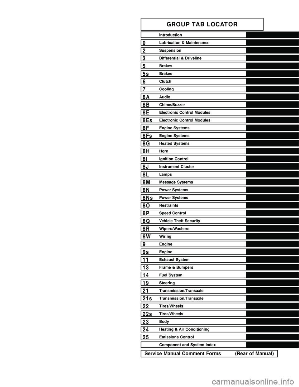
GROUP TAB LOCATOR
Introduction
0Lubrication & Maintenance
2Suspension
3Differential & Driveline
5Brakes
5sBrakes
6Clutch
7Cooling
8AAudio
8BChime/Buzzer
8EElectronic Control Modules
8EsElectronic Control Modules
8FEngine Systems
8FsEngine Systems
8GHeated Systems
8HHorn
8IIgnition Control
8JInstrument Cluster
8LLamps
8MMessage Systems
8NPower Systems
8NsPower Systems
8ORestraints
8PSpeed Control
8QVehicle Theft Security
8RWipers/Washers
8WWiring
9Engine
9sEngine
11Exhaust System
13Frame & Bumpers
14Fuel System
19Steering
21Transmission/Transaxle
21sTransmission/Transaxle
22Tires/Wheels
22sTires/Wheels
23Body
24Heating & Air Conditioning
25Emissions Control
Component and System Index
Service Manual Comment Forms (Rear of Manual)
Page 152 of 2585
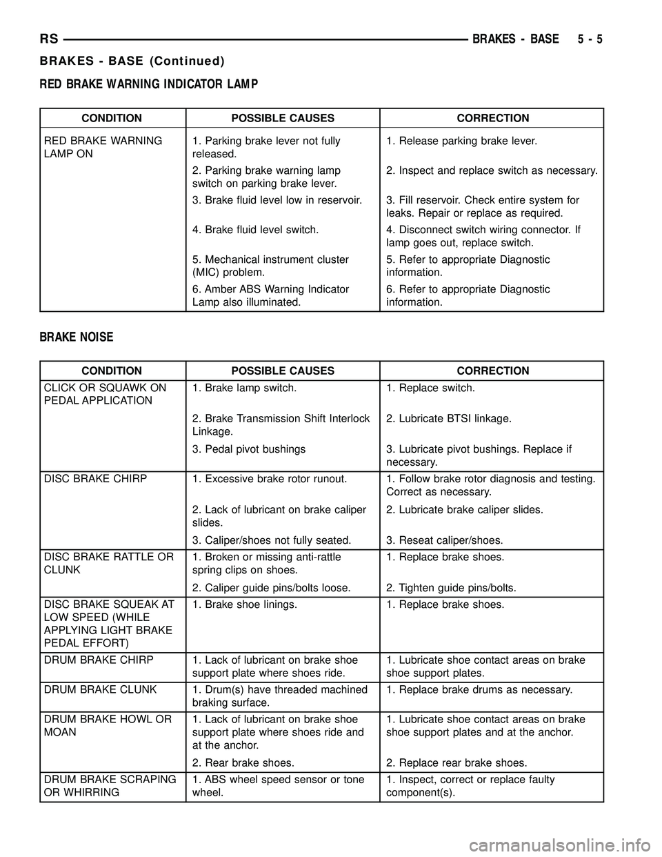
RED BRAKE WARNING INDICATOR LAMP
CONDITION POSSIBLE CAUSES CORRECTION
RED BRAKE WARNING
LAMP ON1. Parking brake lever not fully
released.1. Release parking brake lever.
2. Parking brake warning lamp
switch on parking brake lever.2. Inspect and replace switch as necessary.
3. Brake fluid level low in reservoir. 3. Fill reservoir. Check entire system for
leaks. Repair or replace as required.
4. Brake fluid level switch. 4. Disconnect switch wiring connector. If
lamp goes out, replace switch.
5. Mechanical instrument cluster
(MIC) problem.5. Refer to appropriate Diagnostic
information.
6. Amber ABS Warning Indicator
Lamp also illuminated.6. Refer to appropriate Diagnostic
information.
BRAKE NOISE
CONDITION POSSIBLE CAUSES CORRECTION
CLICK OR SQUAWK ON
PEDAL APPLICATION1. Brake lamp switch. 1. Replace switch.
2. Brake Transmission Shift Interlock
Linkage.2. Lubricate BTSI linkage.
3. Pedal pivot bushings 3. Lubricate pivot bushings. Replace if
necessary.
DISC BRAKE CHIRP 1. Excessive brake rotor runout. 1. Follow brake rotor diagnosis and testing.
Correct as necessary.
2. Lack of lubricant on brake caliper
slides.2. Lubricate brake caliper slides.
3. Caliper/shoes not fully seated. 3. Reseat caliper/shoes.
DISC BRAKE RATTLE OR
CLUNK1. Broken or missing anti-rattle
spring clips on shoes.1. Replace brake shoes.
2. Caliper guide pins/bolts loose. 2. Tighten guide pins/bolts.
DISC BRAKE SQUEAK AT
LOW SPEED (WHILE
APPLYING LIGHT BRAKE
PEDAL EFFORT)1. Brake shoe linings. 1. Replace brake shoes.
DRUM BRAKE CHIRP 1. Lack of lubricant on brake shoe
support plate where shoes ride.1. Lubricate shoe contact areas on brake
shoe support plates.
DRUM BRAKE CLUNK 1. Drum(s) have threaded machined
braking surface.1. Replace brake drums as necessary.
DRUM BRAKE HOWL OR
MOAN1. Lack of lubricant on brake shoe
support plate where shoes ride and
at the anchor.1. Lubricate shoe contact areas on brake
shoe support plates and at the anchor.
2. Rear brake shoes. 2. Replace rear brake shoes.
DRUM BRAKE SCRAPING
OR WHIRRING1. ABS wheel speed sensor or tone
wheel.1. Inspect, correct or replace faulty
component(s).
RSBRAKES - BASE5-5
BRAKES - BASE (Continued)
Page 247 of 2585
CAUTION
CAUTION: During service procedures, grease or
any other foreign material must be kept off brake
shoes and braking surfaces of brake rotor or drum,
and external surfaces of hub and bearing assembly.
CAUTION: Brake rotor and caliper handling must be
done in such a way as to avoid damage to the rotor,
especially the machined surfaces, and scratching or
nicking of the brake linings.
CAUTION: Only the recommended jacking or hoist-
ing procedures for this vehicle are to be usedwhenever it is necessary to lift a vehicle. Failure to
raise a vehicle utilizing the recommended lift points
can result in damage to the vehicle. (Refer to
LUBRICATION & MAINTENANCE/HOISTING - STAN-
DARD PROCEDURE)
DIAGNOSIS AND TESTING - BASE BRAKE
SYSTEM
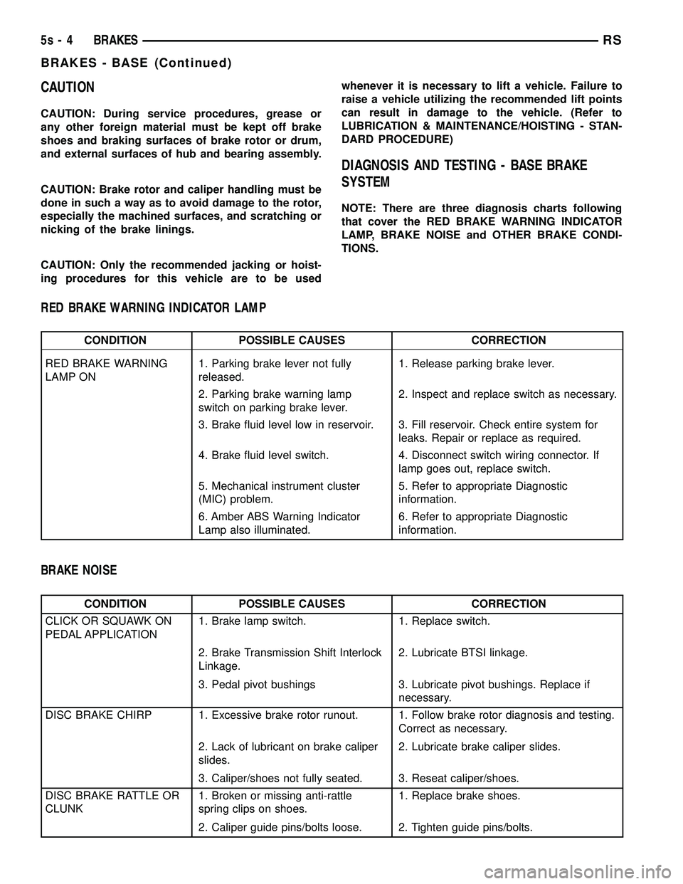
NOTE: There are three diagnosis charts following
that cover the RED BRAKE WARNING INDICATOR
LAMP, BRAKE NOISE and OTHER BRAKE CONDI-
TIONS.
RED BRAKE WARNING INDICATOR LAMP
CONDITION POSSIBLE CAUSES CORRECTION
RED BRAKE WARNING
LAMP ON 1. Parking brake lever not fully
released. 1. Release parking brake lever.
2. Parking brake warning lamp
switch on parking brake lever. 2. Inspect and replace switch as necessary.
3. Brake fluid level low in reservoir. 3. Fill reservoir. Check entire system for leaks. Repair or replace as required.
4. Brake fluid level switch. 4. Disconnect switch wiring connector. If lamp goes out, replace switch.
5. Mechanical instrument cluster
(MIC) problem. 5. Refer to appropriate Diagnostic
information.
6. Amber ABS Warning Indicator
Lamp also illuminated. 6. Refer to appropriate Diagnostic
information.
BRAKE NOISE
CONDITION POSSIBLE CAUSES CORRECTION
CLICK OR SQUAWK ON
PEDAL APPLICATION 1. Brake lamp switch. 1. Replace switch.
2. Brake Transmission Shift Interlock
Linkage. 2. Lubricate BTSI linkage.
3. Pedal pivot bushings 3. Lubricate pivot bushings. Replace if necessary.
DISC BRAKE CHIRP 1. Excessive brake rotor runout. 1. Follow brake rotor diagnosis and testing. Correct as necessary.
2. Lack of lubricant on brake caliper
slides. 2. Lubricate brake caliper slides.
3. Caliper/shoes not fully seated. 3. Reseat caliper/shoes.
DISC BRAKE RATTLE OR
CLUNK 1. Broken or missing anti-rattle
spring clips on shoes. 1. Replace brake shoes.
2. Caliper guide pins/bolts loose. 2. Tighten guide pins/bolts.
5s - 4 BRAKESRS
BRAKES - BASE (Continued)
Page 393 of 2585
(3) Check drivers seat belt buckle switch input
(from Occupant Restraint Controller (ORC) for a
closed circuit when not buckled. If input not seen,
look for open in wiring or switch. The switch is
grounded when belt is not buckled.
(4) Verify Programmable Communication Interface
(PCI) data bus communication between ORC and
BCM.
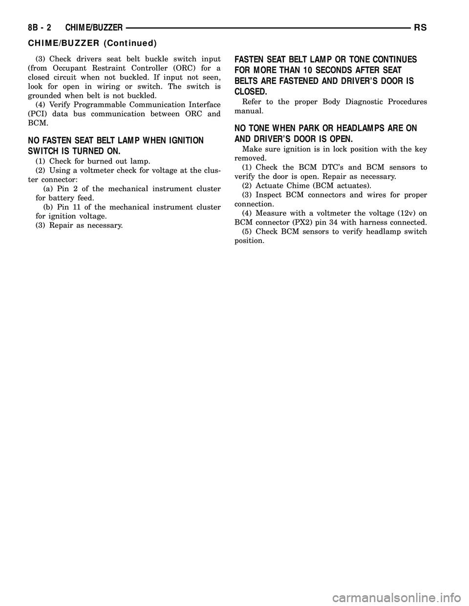
NO FASTEN SEAT BELT LAMP WHEN IGNITION
SWITCH IS TURNED ON.
(1) Check for burned out lamp.
(2) Using a voltmeter check for voltage at the clus-
ter connector:
(a) Pin 2 of the mechanical instrument cluster
for battery feed.
(b) Pin 11 of the mechanical instrument cluster
for ignition voltage.
(3) Repair as necessary.
FASTEN SEAT BELT LAMP OR TONE CONTINUES
FOR MORE THAN 10 SECONDS AFTER SEAT
BELTS ARE FASTENED AND DRIVER'S DOOR IS
CLOSED.
Refer to the proper Body Diagnostic Procedures
manual.
NO TONE WHEN PARK OR HEADLAMPS ARE ON
AND DRIVER'S DOOR IS OPEN.
Make sure ignition is in lock position with the key
removed.
(1) Check the BCM DTC's and BCM sensors to
verify the door is open. Repair as necessary.
(2) Actuate Chime (BCM actuates).
(3) Inspect BCM connectors and wires for proper
connection.
(4) Measure with a voltmeter the voltage (12v) on
BCM connector (PX2) pin 34 with harness connected.
(5) Check BCM sensors to verify headlamp switch
position.
8B - 2 CHIME/BUZZERRS
CHIME/BUZZER (Continued)
Page 396 of 2585
(5) Obtain ignition keys to be programmed from
customer (8 keys maximum).
(6) Using the DRB III, erase all ignition keys by
selecting MISCELLANEOUS and ERASE ALL CUR-
RENT IGN. KEYS.
(7) Program all ignition keys.
Learned Key In Ignition - Ignition key transponder
ID is currently programmed in SKIM memory.
BODY CONTROL MODULE
DESCRIPTION
The Body Control Module (BCM) is located in the
passenger compartment, attached to the bulkhead
underneath the left side of the instrument panel.
The BCM utilizes integrated circuitry and informa-
tion carried on the Programmable Communications
Interface (PCI) data bus network along with many
hard wired inputs to monitor many sensor and
switch inputs throughout the vehicle. In response to
those inputs, the internal circuitry and programming
of the BCM allow it to control and integrate many
electronic functions and features of the vehicle
through both hard wired outputs and the transmis-
sion of electronic message outputs to other electronic
modules in the vehicle over the PCI data bus.
OPERATION
The Body Control Module (BCM) supplies vehicle
occupants with visual and audible information and
controls various vehicle functions. To provide and
receive information, the BCM is interfaced to the
vehicle's serial bus communications network, referred
to as the Programmable Communications Interface
(PCI) bus.
This network consists of the;
²Powertrain Control Module (PCM)
²Transmission Control Module (TCM)
²Mechanical Instrument Cluster (MIC)
²Occupant Restraint Controller (ORC)
²Compass/Mini-Trip Computer (CMTC)
²Electronic Vehicle Information Center (EVIC)
²Controller Antilock Brake (CAB)²HVAC Control Module
²Sliding Door Control Modules (driver and pas-
senger side doors)
²Power Liftgate Module (PLG)
²Audio system equipped with RAZ, RBU, RBK,
and RBB radios.
²Side Impact Airbag Control Module (SIACM)
²Memory Seat Module (MSM)
²Sentry Key Immobilizer Module (SKIM)
The BCM is operational when battery power is
supplied to the module.
The BCM provides the following features:
²Power Door Locks
²Automatic Door Locks
²Battery Protection - The BCM will automatically
turn off all exterior lamps after 3 minutes, and all
interior lamps after 15 minutes after the ignition is
turned off, if they are not turned off by the driver.
²Chime Control
²Compass/Mini-Trip support.
²Interior Lighting (Courtesy/Reading Lamps)
²BCM Diagnostic Reporting
²Electronic Liftgate Release (with Power Door
Locks)
²Exterior Lighting
²Headlamp Time Delay (with/without Automatic
Headlamps)
²Illuminated Entry
²Fade to Off Interior Lamps - This feature dims
the interior lighting (courtesy lamps) gradually if the
BCM does not receive any new inputs that would
cause the interior lamps to remain on.
²Pulse Width Modulated Instrument Panel Dim-
ming
²Door Lock Inhibit - This feature disables the
door lock functions if the key is in the ignition and
either front door is ajar. Pressing the Remote Keyless
Entry (RKE) lock/unlock button under these condi-
tions result in normal lock/unlock activation.
The BCM has the ability to LEARN additional fea-
tures in the vehicle, provided the appropriate switch
input and PCI data bus messages are received. Refer
to the LEARNED FEATURES table.
RSELECTRONIC CONTROL MODULES8E-3
ELECTRONIC CONTROL MODULES (Continued)
Page 399 of 2585
be automatically cleared from the CAB memory after
the identical fault has not been seen during the next
3,500 miles. Drive-off may be required for the amber
ABS warning indicator lamp to go out on the next
ignition cycle.
CAB INPUTS
²Wheel speed sensors (four)
²Brake lamp switch
²Ignition switch
²System and pump voltage
²Ground
²Traction control switch (if equipped)
²Diagnostic communication (PCI)
CAB OUTPUTS
²Amber ABS warning indicator lamp actuation
(via BUS)
²Red BRAKE warning indicator lamp actuation
(via BUS)
²Instrument cluster (MIC) communication (PCI)
²Traction control lamps (if equipped)
²Diagnostic communication (PCI, via BUS)
REMOVAL
(1) Disconnect the battery cables.
(2) Remove the battery (Refer to 8 - ELECTRI-
CAL/BATTERY SYSTEM/BATTERY - REMOVAL).
(3) Disconnect the vacuum hose connector at the
tank built into the battery tray.
(4) Remove the screw securing the coolant filler
neck to the battery tray.
(5) Remove the battery tray (Refer to 8 - ELEC-
TRICAL/BATTERY SYSTEM/TRAY - REMOVAL).
(6) Pull up on the CAB connector lock and discon-
nect the 24±way electrical connector (Fig. 2).
(7) Disconnect the pump/motor connector from the
CAB.
(8) Remove the screws securing the CAB to the
HCU (Fig. 3)
(9) Pull CAB straight forward off HCU.
INSTALLATION
(1) Slide the CAB onto the HCU (Fig. 3).
(2) Install screws securing the CAB to the HCU
(Fig. 3) Tighten the mounting screws to 2 N´m (17 in
lbs).
(3) Reconnect the 24±way wiring connector and
the pump/motor wiring connector. (Fig. 2)
(4) Install the battery tray (Refer to 8 - ELECTRI-
CAL/BATTERY SYSTEM/TRAY - INSTALLATION).
(5) Install the screw securing the coolant filler
neck to the battery tray.
(6) Reconnect the vacuum hose to the coolant tank
built into the battery tray.(7) Install the battery (Refer to 8 - ELECTRICAL/
BATTERY SYSTEM/BATTERY - INSTALLATION).
(8) Reconnect the battery cables.
(9) Connect a DRBIIItto the vehicle. Check and
clear any faults, and initialize the system.
DATA LINK CONNECTOR
DESCRIPTION
The data link connector is located inside the vehi-
cle, below instrument panel next to the center col-
umn (Fig. 4).
Fig. 2 CAB Connector Lock
1 - CONNECTOR LOCK
2 - CAB
Fig. 3 CAB Mounting Screws
1 - HCU
2 - MOUNTING SCREWS
3 - CAB
8E - 6 ELECTRONIC CONTROL MODULESRS
CONTROLLER ANTILOCK BRAKE (Continued)
Page 411 of 2585
Refer to the appropriate Powertrain Diagnostic Man-
ual and the DRBIIItscan tool.
(1) Install PCM module to the mounting bracket.
(2) Install electrical connectors and lock.
(3) Install the splash shield.
(4) Lower vehicle.
(5) Connect the negative battery cable.
(6) Using DRBIIItscan tool, program mileage and
vehicle identification number (VIN) into PCM. Refer
to the DRBIIItscan tool and the appropriate Power-
train Diagnostic Manual.
SENTRY KEY IMMOBILIZER
MODULE
DESCRIPTION
The Sentry Key Immobilizer Module (SKIM) con-
tains a Radio Frequency (RF) transceiver and a
microprocessor. The SKIM retains in memory the ID
numbers of any Sentry Key that is programmed to it.
The maximum number of keys that may be pro-
grammed to each module is eight (8). The SKIM also
communicates over the Programmable Communica-
tion Interface (PCI) data bus with the Powertrain
Control Module (PCM), the Body Control Module
(BCM), the Mechanical Instrument Cluster (MIC),
and the DRB IIItscan tool. The SKIM transmits and
receives RF signals through a tuned antenna
enclosed within a molded plastic ring formation that
is integral to the SKIM housing. When the SKIM is
properly installed on the steering column, the
antenna ring fits snugly around the circumference of
the ignition lock cylinder housing. If this ring is not
mounted properly, communication problems may
arise in the form of transponder-related faults.
For added system security, each SKIM is pro-
grammed with a unique9Secret Key9code. This code
is stored in memory and is sent over the PCI bus to
the PCM and to each key that is programmed to
work with the vehicle. The9Secret Key9code is there-
fore a common element found in all components of
the Sentry Key Immobilizer System (SKIS). In the
event that a SKIM replacement is required, the
9Secret Key9code can be restored from the PCM by
following the SKIM replacement procedure found in
the DRB IIItscan tool. Proper completion of this
task will allow the existing ignition keys to be repro-
grammed. Therefore, new keys will NOT be needed.
In the event that the original9Secret Key9code can
not be recovered, new ignition keys will be required.
The DRB IIItscan tool will alert the technician if
key replacement is necessary. Another security code,
called a PIN, is used to gain secured access to the
SKIM for service. The SKIM also stores in its mem-
ory the Vehicle Identification Number (VIN), which itlearns through a bus message from the assembly
plant tester. The SKIS scrambles the information
that is communicated between its components in
order to reduce the possibility of unauthorized SKIM
access and/or disabling.
OPERATION
When the ignition switch is moved to the RUN
position, the Sentry Key Immobilizer Module (SKIM)
transmits an Radio Frequency (RF) signal to the
transponder in the ignition key. The SKIM then
waits for a response RF signal from the transponder
in the key. If the response received identifies the key
as valid, the SKIM sends a9valid key9message to
the Powertrain Control Module (PCM) over the Pro-
grammable Communication Interface (PCI) data bus.
If the response received identifies the key as invalid
or no response is received from the transponder in
the ignition key, the SKIM sends an9invalid key9
message to the PCM. The PCM will enable or disable
engine operation based upon the status of the SKIM
messages. It is important to note that the default
condition in the PCM is9invalid key.9Therefore, if no
response is received by the PCM, the engine will be
immobilized after two (2) seconds of running.
The SKIM also sends indicator light status mes-
sages to the Mechanical Instrument Cluster (MIC) to
operate the light. This is the method used to turn the
light ON solid or to flash it after the indicator light
test is complete to signify a fault in the SKIS. If the
light comes ON and stays ON solid after the indica-
tor light test, this signifies that the SKIM has
detected a system malfunction and/or that the SKIS
has become inoperative. If the SKIM detects an
invalid keyORa key-related fault exists, the indica-
tor light will flash following the indicator light test.
The SKIM may also request an audible chime if the
customer key programming feature is available and
the procedure is being utilized (Refer to 8 - ELEC-
TRICAL/VEHICLE THEFT SECURITY/TRANSPON-
DER KEY - STANDARD PROCEDURE).
REMOVAL
(1) Disconnect and isolate the battery negative
cable.
(2) Remove Lower Instrument Panel Cover. Refer
to Body, Instrument Panel, Lower Instrument Panel
Cover, Removal.
(3) Remove the steering column upper and lower
shrouds. Refer to Steering, Column, Column Shroud,
Removal.
(4) Disengage the steering column wire harness
from the Sentry Key Immobilizer Module (SKIM).
(5) Remove the one screws securing the SKIM to
the steering column.
8E - 18 ELECTRONIC CONTROL MODULESRS
POWERTRAIN CONTROL MODULE (Continued)
Page 418 of 2585
BODY CONTROL MODULE
TABLE OF CONTENTS
page page
BODY CONTROL MODULE DESCRIPTION ..........................1
OPERATION ............................1 REMOVAL
.............................3
INSTALLATION ..........................3
BODY CONTROL MODULE
DESCRIPTION
The Body Control Module (BCM) is located in the
passenger compartment, attached to the bulkhead
underneath the left side of the instrument panel. The BCM utilizes integrated circuitry and informa-
tion carried on the Programmable Communications
Interface (PCI) data bus network along with many
hard wired inputs to monitor many sensor and
switch inputs throughout the vehicle. In response to
those inputs, the internal circuitry and programming
of the BCM allow it to control and integrate many
electronic functions and features of the vehicle
through both hard wired outputs and the transmis-
sion of electronic message outputs to other electronic
modules in the vehicle over the PCI data bus.
OPERATION
The Body Control Module (BCM) supplies vehicle
occupants with visual and audible information and
controls various vehicle functions. To provide and
receive information, the BCM is interfaced to the
vehicle's serial bus communications network, referred
to as the Programmable Communications Interface
(PCI) bus. This network consists of the;
² Powertrain Control Module (PCM)
² Transmission Control Module (TCM)
² Mechanical Instrument Cluster (MIC)
² Occupant Restraint Controller (ORC)
² Compass/Mini-Trip Computer (CMTC)
² Electronic Vehicle Information Center (EVIC)
² Controller Antilock Brake (CAB)
² HVAC Control Module
² Sliding Door Control Modules (driver and pas-
senger side doors) ² Power Liftgate Module (PLG) ²
Audio system equipped with RAZ, RBU, RBK,
and RBB radios. ² Sentry Key Remote Entry Module (SKREEM).
² Side Impact Airbag Control Module (SIACM)
² Memory Seat Module (MSM)
² Sentry Key Immobilizer Module (SKIM)
The BCM is operational when battery power is
supplied to the module. The BCM provides the following features:
² Power Door Locks
² Automatic Door Locks
² Battery Protection - The BCM will automatically
turn off all exterior lamps after 3 minutes, and all
interior lamps after 15 minutes after the ignition is
turned off, if they are not turned off by the driver. ² Chime Control
² Compass/Mini-Trip support.
² Interior Lighting (Courtesy/Reading Lamps)
² BCM Diagnostic Reporting
² Electronic Liftgate Release (with Power Door
Locks) ² Exterior Lighting
² Headlamp Time Delay (with/without Automatic
Headlamps) ² Illuminated Entry
² Fade to Off Interior Lamps - This feature dims
the interior lighting (courtesy lamps) gradually if the
BCM does not receive any new inputs that would
cause the interior lamps to remain on. ² Pulse Width Modulated Instrument Panel Dim-
ming ² Door Lock Inhibit - This feature disables the
door lock functions if the key is in the ignition and
either front door is ajar. Pressing the Remote Keyless
Entry (RKE) lock/unlock button under these condi-
tions result in normal lock/unlock activation. The BCM has the ability to LEARN additional fea-
tures in the vehicle, provided the appropriate switch
input and PCI data bus messages are received. Refer
to the LEARNED FEATURES table.
RS BODY CONTROL MODULE8Es-1
Page 441 of 2585
CHARGING
TABLE OF CONTENTS
page page
CHARGING
DESCRIPTION - CHARGING SYSTEM.......20
OPERATION - CHARGING SYSTEM.........20
DIAGNOSIS AND TESTING - ON-BOARD
DIAGNOSTIC SYSTEM.................21
SPECIFICATIONS
GENERATOR........................22
TORQUE............................22
SPECIFICATIONS - BATTERY
TEMPERATURE SENSOR...............22
SPECIAL TOOLS.......................23
BATTERY TEMPERATURE SENSOR
DESCRIPTION.........................23
OPERATION...........................23
REMOVAL.............................23
GENERATOR
DESCRIPTION.........................23OPERATION...........................23
REMOVAL
REMOVAL - 2.4L......................23
REMOVAL - 3.3/3.8L...................24
INSTALLATION
INSTALLATION - 2.4L..................24
INSTALLATION - 3.3/3.8L................24
GENERATOR DECOUPLER PULLEY
DESCRIPTION.........................25
OPERATION...........................25
DIAGNOSIS AND TESTING - GENERATOR
DECOUPLER PULLEY..................25
REMOVAL.............................26
INSTALLATION.........................26
VOLTAGE REGULATOR
DESCRIPTION.........................27
OPERATION...........................27
CHARGING
DESCRIPTION - CHARGING SYSTEM
The charging system consists of:
²Generator
²Decoupler Pulley (If equipped)
²Electronic Voltage Regulator (EVR) circuitry
within the Powertrain Control Module (PCM)
²Ignition switch (refer to the Ignition System sec-
tion for information)
²Battery (refer to the Battery section for informa-
tion)
²Ambient Air Temperature (If equipped)
²Inlet Air Temperature (calculated battery tem-
perature)(If equipped)
²Voltmeter (refer to the Instrument Cluster sec-
tion for information if equipped)
²Wiring harness and connections (refer to the
Wiring section for information)
²Accessory drive belt (refer to the Cooling section
for more information)
²Battery Temperature sensor (if equipped)
OPERATION - CHARGING SYSTEM
The charging system is turned on and off with the
ignition switch. The system is on when the engine is
running and the ASD relay is energized. The ASD
relay is energized when the PCM grounds the ASD
control circuit. (SBEC vehicles) This voltage is con-
nected through the PCM or IPM (intelligent powermodule) (if equipped) and supplied to one of the gen-
erator field terminals (Gen. Source +) at the back of
the generator.
The generator is driven by the engine through a
serpentine belt and pulley or decoupler pulley
arrangement.
The amount of DC current produced by the gener-
ator is controlled by the EVR (field control) circuitry
contained within the PCM. This circuitry is con-
nected in series with the second rotor field terminal
and ground.
(SBEC vehicles) An Inlet air temperature sensor is
used to calculate the temperature near the battery.
This temperature data, along with data from moni-
tored line voltage (battery voltage sense circuit), is
used by the PCM to vary the battery charging rate.
This is done by cycling the ground path to control the
strength of the rotor magnetic field. The PCM then
compensates and regulates generator current output
accordingly to maintain system voltage at the tar-
geted system voltage based on battery temperature.
All vehicles are equipped with On-Board Diagnos-
tics (OBD). All OBD-sensed systems, including EVR
(field control) circuitry, are monitored by the PCM.
Each monitored circuit is assigned a Diagnostic Trou-
ble Code (DTC). The PCM will store a DTC in elec-
tronic memory for certain failures it detects and
illuminate the (MIL) lamp. Refer to On-Board Diag-
nostics in the Electronic Control Modules(Refer to 8 -
ELECTRICAL/ELECTRONIC CONTROL MOD-
8F - 20 CHARGINGRS
Page 442 of 2585
ULES/POWERTRAIN CONTROL MODULE -
DESCRIPTION) section for more DTC information.
The Check Gauges Lamp (if equipped) or Battery
Lamp monitors:charging system voltage,engine
coolant temperature and engine oil pressure. If an
extreme condition is indicated, the lamp will be illu-
minated. The signal to activate the lamp is sent via
the PCI bus circuits. The lamp is located on the
instrument panel. Refer to the Instrument Cluster
section for additional information.
(If equipped with inlet air temperature sensor) The
PCM uses the inlet air temperature sensor to control
the charge system voltage. This temperature, along
with data from monitored line voltage, is used by the
PCM to vary the battery charging rate. The system
voltage is higher at cold temperatures and is gradu-
ally reduced as the calculated battery temperature
increases.
The ambient temperature sensor is used to control
the battery voltage based upon ambient temperature
(approximation of battery temperature). The PCM
maintains the optimal output of the generator by
monitoring battery voltage and controlling it to a
range of 13.5 - 14.7 volts based on battery tempera-
ture. The system target voltage is 13.5 ± 14.7 volts.
However the actual voltage go below this during
heavy electrical loads and generator speeds. Also the
actual voltage can be lower than the target voltage
between the battery and the battery voltage sense
circuit, approximately 0.2 Ð 0.3 volts.
DIAGNOSIS AND TESTING - ON-BOARD
DIAGNOSTIC SYSTEM
The Powertrain Control Module (PCM) monitors
critical input and output circuits of the charging sys-
tem, making sure they are operational. A Diagnostic
Trouble Code (DTC) is assigned to each input and
output circuit monitored by the OBD system. Some
circuits are checked continuously and some are
checked only under certain conditions.
If the OBD system senses that a monitored circuit
is bad, it will put a DTC into electronic memory. The
DTC will stay in electronic memory as long as the
circuit continues to be bad. The PCM is programmed
to clear the memory after 40 good trip if the problem
does not occur again.
DIAGNOSTIC TROUBLE CODES
A DTC description can be read using the DRBIIIt
scan tool. Refer to the appropriate Powertrain Diag-
nostic Procedures manual for information.
A DTC does not identify which component in a cir-
cuit is bad. Thus, a DTC should be treated as a
symptom, not as the cause for the problem. In some
cases, because of the design of the diagnostic test
procedure, a DTC can be the reason for another DTCto be set. Therefore, it is important that the test pro-
cedures be followed in sequence, to understand what
caused a DTC to be set.
ERASING DIAGNOSTIC TROUBLE CODES
The DRBIIItScan Tool must be used to erase a
DTC.
The following procedures may be used to diagnose
the charging system if:
²the check gauges lamp or battery lamp is illumi-
nated with the engine running
²the voltmeter (if equipped) does not register
properly
²an undercharged or overcharged battery condi-
tion occurs.
Remember that an undercharged battery is often
caused by:
²accessories being left on with the engine not
running
²a faulty or improperly adjusted switch that
allows a lamp to stay on. Refer to Ignition-Off Draw
Test (Refer to 8 - ELECTRICAL/BATTERY SYSTEM/
BATTERY - STANDARD PROCEDURE)
²loose generator belt.
INSPECTION
The Powertrain Control Module (PCM) monitors
critical input and output circuits of the charging sys-
tem, making sure they are operational. A Diagnostic
Trouble Code (DTC) is assigned to each input and
output circuit monitored by the On-Board Diagnostic
(OBD) system. Some charging system circuits are
checked continuously, and some are checked only
under certain conditions.
Refer to Diagnostic Trouble Codes in; Powertrain
Control Module; Electronic Control Modules for more
DTC information. This will include a complete list of
DTC's including DTC's for the charging system.
To perform a complete test of the charging system,
refer to the appropriate Powertrain Diagnostic Proce-
dures service manual and the DRBIIItscan tool.
Perform the following inspections before attaching
the scan tool.
(1) Inspect the battery condition. Refer to the Bat-
tery section (Refer to 8 - ELECTRICAL/BATTERY
SYSTEM - DIAGNOSIS AND TESTING) for proce-
dures.
(2) Inspect condition of battery cable terminals,
battery posts, connections at engine block, starter
solenoid and relay. They should be clean and tight.
Repair as required.
(3) Inspect all fuses in both the fuseblock and
Power Distribution Center (PDC) or IPM (if
equipped) for tightness in receptacles. They should be
properly installed and tight. Repair or replace as
required.
RSCHARGING8F-21
CHARGING (Continued)