service CHRYSLER VOYAGER 2005 Owners Manual
[x] Cancel search | Manufacturer: CHRYSLER, Model Year: 2005, Model line: VOYAGER, Model: CHRYSLER VOYAGER 2005Pages: 2339, PDF Size: 59.69 MB
Page 315 of 2339

ly-charged, but does not pass the Micro 420 or load
test, is inoperative and must be replaced.
NOTE: Completely discharged batteries may take
several hours to accept a charge. (Refer to 8 -
ELECTRICAL/BATTERY SYSTEM/BATTERY - STAN-
DARD PROCEDURE) for the proper battery charging
procedures.
STANDARD PROCEDURE
SPIRAL PLATE BATTERY CHARGING
Vehicles equipped with a diesel engine utilize a
unique spiral plate battery. This battery has a maxi-
mum charging voltage that must not be exceeded in
order to restore the battery to its full potential, fail-
ure to use the following spiral plate battery charging
procedure could result in damage to the battery or
personal injury.
Battery charging is the means by which the bat-
tery can be restored to its full voltage potential. A
battery is fully-charged when:
²Micro 420 battery tester indicates battery is OK.
²Open-circuit voltage of the battery is 12.65 volts
or above.
²Battery passes Load Test multiple times.
WARNING: IF THE BATTERY SHOWS SIGNS OF
FREEZING, LEAKING, LOOSE POSTS OR LOW
ELECTROLYTE LEVEL, DO NOT TEST, ASSIST-
BOOST, OR CHARGE. THE BATTERY MAY ARC
INTERNALLY AND EXPLODE. PERSONAL INJURY
AND/OR VEHICLE DAMAGE MAY RESULT.
CAUTION: Always disconnect and isolate the bat-
tery negative cable before charging a battery.
Charge the battery directly at the battery terminals.
Do not exceed 14.4 volts while charging a battery.
CAUTION: The battery should not be hot to the
touch. If the battery feels hot to the touch, turn off
the charger and let the battery cool before continu-
ing the charging operation. Damage to the battery
may result.
After the battery has been charged to 12.6 volts or
greater, perform a load test to determine the battery
cranking capacity. (Refer to 8 - ELECTRICAL/BAT-
TERY SYSTEM/BATTERY - STANDARD PROCE-
DURE - USING THE MICRO 420 BATTERY
TESTER) for the proper battery test procedures. If
the battery passes a load test, return the battery to
service. If the battery will not pass a load test, it is
inoperative and must be replaced.Clean and inspect the battery hold downs, tray,
terminals, posts, and top before completing battery
service. (Refer to 8 - ELECTRICAL/BATTERY SYS-
TEM - CLEANING) for the proper battery system
cleaning procedures, and (Refer to 8 - ELECTRICAL/
BATTERY SYSTEM - INSPECTION) for the proper
battery system inspection procedures.
CHARGING A COMPLETELY DISCHARGED
BATTERY ± SPIRAL PLATE BATTERY
The following procedure should be used to recharge
a completely discharged battery. Unless this proce-
dure is properly followed, a good battery may be
needlessly replaced.
(1) Measure the voltage at the battery posts with a
voltmeter, accurate to 1/10 (0.10) volt (Fig. 7). (Refer
to 8 - ELECTRICAL/BATTERY SYSTEM/BATTERY -
REMOVAL) for instructions on how to access the bat-
tery. If the reading is below ten volts, the battery
charging current will be low. It could take several
hours before the battery accepts a current greater
than a few milliamperes. Such low current may not
be detectable on the ammeters built into many bat-
tery chargers.
(2) Disconnect and isolate the battery negative
cable. Connect the battery charger leads. Some bat-
tery chargers are equipped with polarity-sensing cir-
cuitry. This circuitry protects the battery charger and
the battery from being damaged if they are improp-
erly connected. If the battery state-of-charge is too
low for the polarity-sensing circuitry to detect, the
battery charger will not operate. This makes it
appear that the battery will not accept charging cur-
rent. See the instructions provided by the manufac-
turer of the battery charger for details on how to
bypass the polarity-sensing circuitry.
(3) Battery chargers vary in the amount of voltage
and current they provide. The amount of time
required for a battery to accept measurable charging
current at various voltages is shown in the Charge
Fig. 7 Voltmeter - Typical
8F - 10 BATTERY SYSTEMRS
BATTERY (Continued)
Page 317 of 2339
CAUTION: Battery electrolyte will bubble inside the
battery case during normal battery charging. Elec-
trolyte boiling or being discharged from the battery
vents indicates a battery overcharging condition.
Immediately reduce the charging rate or turn off the
charger to evaluate the battery condition. Damage
to the battery may result from overcharging.
CAUTION: The battery should not be hot to the
touch. If the battery feels hot to the touch, turn off
the charger and let the battery cool before continu-
ing the charging operation. Damage to the battery
may result.
After the battery has been charged to an open-cir-
cuit voltage reading of 12.4 volts or greater, retest
the battery with the Micro 420 tester or perform a
load test to determine the battery cranking capacity.
(Refer to 8 - ELECTRICAL/BATTERY SYSTEM/BAT-
TERY - STANDARD PROCEDURE) for the proper
battery load test procedures. If the battery passes a
load test, return the battery to service. If the battery
will not pass a load test, it is inoperative and must
be replaced.
Clean and inspect the battery hold downs, tray,
terminals, posts, and top before completing battery
service. (Refer to 8 - ELECTRICAL/BATTERY SYS-
TEM - CLEANING) for the proper battery system
cleaning procedures, and (Refer to 8 - ELECTRICAL/
BATTERY SYSTEM - INSPECTION) for the proper
battery system inspection procedures.
CHARGING A COMPLETELY DISCHARGED
CONVENTIONAL BATTERY
The following procedure should be used to recharge
a completely discharged battery. Unless this proce-
dure is properly followed, a good battery may be
needlessly replaced.
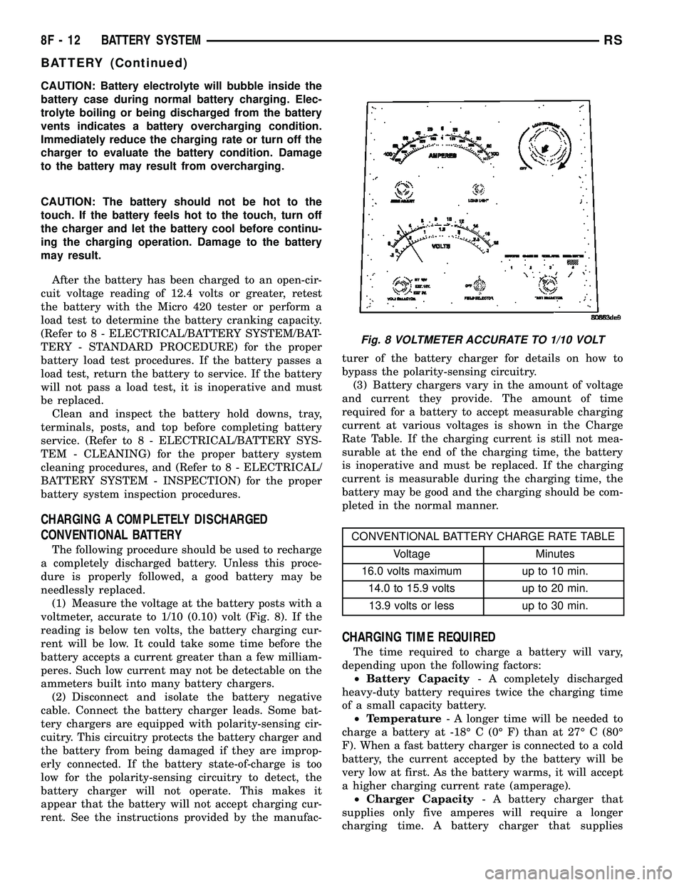
(1) Measure the voltage at the battery posts with a
voltmeter, accurate to 1/10 (0.10) volt (Fig. 8). If the
reading is below ten volts, the battery charging cur-
rent will be low. It could take some time before the
battery accepts a current greater than a few milliam-
peres. Such low current may not be detectable on the
ammeters built into many battery chargers.
(2) Disconnect and isolate the battery negative
cable. Connect the battery charger leads. Some bat-
tery chargers are equipped with polarity-sensing cir-
cuitry. This circuitry protects the battery charger and
the battery from being damaged if they are improp-
erly connected. If the battery state-of-charge is too
low for the polarity-sensing circuitry to detect, the
battery charger will not operate. This makes it
appear that the battery will not accept charging cur-
rent. See the instructions provided by the manufac-turer of the battery charger for details on how to
bypass the polarity-sensing circuitry.
(3) Battery chargers vary in the amount of voltage
and current they provide. The amount of time
required for a battery to accept measurable charging
current at various voltages is shown in the Charge
Rate Table. If the charging current is still not mea-
surable at the end of the charging time, the battery
is inoperative and must be replaced. If the charging
current is measurable during the charging time, the
battery may be good and the charging should be com-
pleted in the normal manner.
CONVENTIONAL BATTERY CHARGE RATE TABLE
Voltage Minutes
16.0 volts maximum up to 10 min.
14.0 to 15.9 volts up to 20 min.
13.9 volts or less up to 30 min.
CHARGING TIME REQUIRED
The time required to charge a battery will vary,
depending upon the following factors:
²Battery Capacity- A completely discharged
heavy-duty battery requires twice the charging time
of a small capacity battery.
²Temperature- A longer time will be needed to
charge a battery at -18É C (0É F) than at 27É C (80É
F). When a fast battery charger is connected to a cold
battery, the current accepted by the battery will be
very low at first. As the battery warms, it will accept
a higher charging current rate (amperage).
²Charger Capacity- A battery charger that
supplies only five amperes will require a longer
charging time. A battery charger that supplies
Fig. 8 VOLTMETER ACCURATE TO 1/10 VOLT
8F - 12 BATTERY SYSTEMRS
BATTERY (Continued)
Page 318 of 2339
twenty amperes or more will require a shorter charg-
ing time.
²State-Of-Charge- A completely discharged bat-
tery requires more charging time than a partially
discharged battery. Electrolyte is nearly pure water
in a completely discharged battery. At first, the
charging current (amperage) will be low. As the bat-
tery charges, the specific gravity of the electrolyte
will gradually rise.
The Conventional Battery Charging Time Table
gives an indication of the time required to charge a
typical battery at room temperature based upon the
battery state-of-charge and the charger capacity.
CONVENTIONAL BATTERY CHARGING TIME TABLE
Charging
Amperage5 Amps10
Amps20 Amps
Open Circuit
VoltageHours Charging @ 21É C (70É
F)
12.25 to 12.49 6 hours 3 hours 1.5
hours
12.00 to 12.24 10 hours 5 hours 2.5
hours
10.00 to 11.99 14 hours 7 hours 3.5
hours
Below 10.00 18 hours 9 hours 4.5
hours
OPEN-CIRCUIT VOLTAGE TEST
A battery open-circuit voltage (no load) test will
show the approximate state-of-charge of a battery.
This test can be used if no other battery tester is
available.
Before proceeding with this test, completely charge
the battery. (Refer to 8 - ELECTRICAL/BATTERY
SYSTEM/BATTERY - STANDARD PROCEDURE) for
the proper battery charging procedures.
(1) Before measuring the open-circuit voltage, the
surface charge must be removed from the battery.
Turn on the headlamps for fifteen seconds, then
allow up to five minutes for the battery voltage to
stabilize.
(2) Disconnect and isolate both battery cables, neg-
ative cable first.
(3) Using a voltmeter connected to the battery
posts (see the instructions provided by the manufac-
turer of the voltmeter), measure the open-circuit volt-
age.
See the Open-Circuit Voltage Table. This voltage
reading will indicate the battery state-of-charge, but
will not reveal its cranking capacity. If a battery has
an open-circuit voltage reading of 12.4 volts or
greater, it may be load tested to reveal its crankingcapacity. (Refer to 8 - ELECTRICAL/BATTERY SYS-
TEM/BATTERY - STANDARD PROCEDURE -
USING THE MICRO 420 BATTERY TESTER) for
the proper battery load test procedures.
OPEN CIRCUIT VOLTAGE TABLE
Open Circuit Voltage Charge Percentage
11.7 volts or less 0%
12.0 volts 25%
12.2 volts 50%
12.45 volts 75%
12.65 volts or more 100%
IGNITION-OFF DRAW TEST
The term Ignition-Off Draw (IOD) identifies a nor-
mal condition where power is being drained from the
battery with the ignition switch in the Off position. A
normal vehicle electrical system will draw from fif-
teen to twenty-five milliamperes (0.015 to 0.025
ampere) with the ignition switch in the Off position,
and all non-ignition controlled circuits in proper
working order. Up to twenty-five milliamperes are
needed to enable the memory functions for the Pow-
ertrain Control Module (PCM), digital clock, electron-
ically tuned radio, and other modules which may
vary with the vehicle equipment.
A vehicle that has not been operated for approxi-
mately twenty-one days, may discharge the battery
to an inadequate level. When a vehicle will not be
used for twenty-one days or more (stored), remove
the IOD fuse from the Integrated Power Module
(IPM). This will reduce battery discharging.
Excessive IOD can be caused by:
²Electrical items left on.
²Faulty or improperly adjusted switches.
²Faulty or shorted electronic modules and compo-
nents.
²An internally shorted generator.
²Intermittent shorts in the wiring.
If the IOD is over twenty-five milliamperes, the
problem must be found and corrected before replac-
ing a battery. In most cases, the battery can be
charged and returned to service after the excessive
IOD condition has been corrected.
(1) Verify that all electrical accessories are off.
Turn off all lamps, remove the ignition key, and close
all doors. If the vehicle is equipped with an illumi-
nated entry system or an electronically tuned radio,
allow the electronic timer function of these systems
to automatically shut off (time out). This may take
up to twenty minutes.
(2) Disconnect the battery negative cable.
RSBATTERY SYSTEM8F-13
BATTERY (Continued)
Page 321 of 2339
press the ENTER button to view the SERVICE
CODE. Pressing the CODE button a second time will
return you to the test results.
BATTERY TEST RESULTS
GOOD BATTERY Return to service
GOOD - RECHARGE Fully charge battery and
return to service
CHARGE & RETEST Fully charge battery and
retest battery
REPLACE BATTERY Replace the battery and
retest complete system
BAD-CELL REPLACE Replace the battery and
retest complete system
NOTE: The SERVICE CODE is required on every
warranty claim submitted for battery replacement.
REMOVAL - BATTERY
WARNING: A SUITABLE PAIR OF HEAVY DUTY
RUBBER GLOVES AND SAFETY GLASSES SHOULD
BE WORN WHEN REMOVING OR SERVICING A
BATTERY.
WARNING: REMOVE METALLIC JEWELRY TO
AVOID INJURY BY ACCIDENTAL ARCING OF BAT-
TERY CURRENT.
(1) Verify that the ignition switch and all accesso-
ries are OFF.
(2) Disconnect the battery cables from the battery
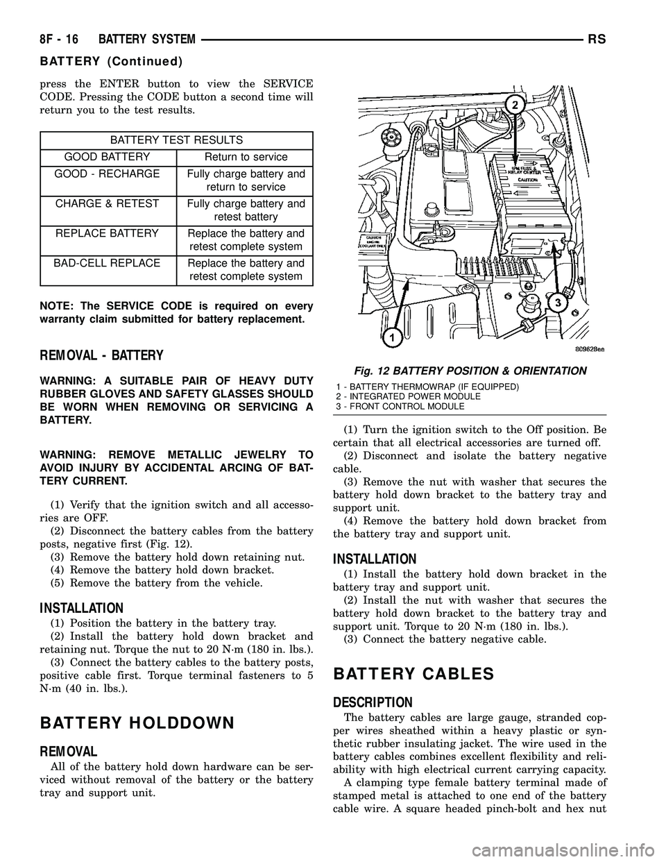
posts, negative first (Fig. 12).
(3) Remove the battery hold down retaining nut.
(4) Remove the battery hold down bracket.
(5) Remove the battery from the vehicle.
INSTALLATION
(1) Position the battery in the battery tray.
(2) Install the battery hold down bracket and
retaining nut. Torque the nut to 20 N´m (180 in. lbs.).
(3) Connect the battery cables to the battery posts,
positive cable first. Torque terminal fasteners to 5
N´m (40 in. lbs.).
BATTERY HOLDDOWN
REMOVAL
All of the battery hold down hardware can be ser-
viced without removal of the battery or the battery
tray and support unit.(1) Turn the ignition switch to the Off position. Be
certain that all electrical accessories are turned off.
(2) Disconnect and isolate the battery negative
cable.
(3) Remove the nut with washer that secures the
battery hold down bracket to the battery tray and
support unit.
(4) Remove the battery hold down bracket from
the battery tray and support unit.
INSTALLATION
(1) Install the battery hold down bracket in the
battery tray and support unit.
(2) Install the nut with washer that secures the
battery hold down bracket to the battery tray and
support unit. Torque to 20 N´m (180 in. lbs.).
(3) Connect the battery negative cable.
BATTERY CABLES
DESCRIPTION
The battery cables are large gauge, stranded cop-
per wires sheathed within a heavy plastic or syn-
thetic rubber insulating jacket. The wire used in the
battery cables combines excellent flexibility and reli-
ability with high electrical current carrying capacity.
A clamping type female battery terminal made of
stamped metal is attached to one end of the battery
cable wire. A square headed pinch-bolt and hex nut
Fig. 12 BATTERY POSITION & ORIENTATION
1 - BATTERY THERMOWRAP (IF EQUIPPED)
2 - INTEGRATED POWER MODULE
3 - FRONT CONTROL MODULE
8F - 16 BATTERY SYSTEMRS
BATTERY (Continued)
Page 322 of 2339
are installed at the open end of the female battery
terminal clamp. Large eyelet type terminals are
crimped onto the opposite end of the battery cable
wire and then solder-dipped. The battery positive
cable wires have a red insulating jacket to provide
visual identification and feature a larger female bat-
tery terminal clamp to allow connection to the larger
battery positive terminal post. The battery negative
cable wires have a black insulating jacket and a
smaller female battery terminal clamp.
The battery cables cannot be repaired and, if dam-
aged or faulty they must be replaced. Both the bat-
tery positive and negative cables are available for
service replacement only as a unit with the battery
wire harness, which may include portions of the wir-
ing circuits for the generator and other components
on some vehicles. Refer to the appropriate wiring
information for complete circuit schematic or connec-
tor pin-out information.
OPERATION
The battery cables connect the battery terminal
posts to the vehicle electrical system. These cables
also provide a path back to the battery for electrical
current generated by the charging system for restor-
ing the voltage potential of the battery. The female
battery terminal clamps on the ends of the battery
cable wires provide a strong and reliable connection
of the battery cable to the battery terminal posts.
The terminal pinch bolts allow the female terminal
clamps to be tightened around the male terminal
posts on the top of the battery. The eyelet terminals
secured to the opposite ends of the battery cable
wires from the female battery terminal clamps pro-
vide secure and reliable connection of the battery
cables to the vehicle electrical system.
The battery positive cable terminal clamp is
attached to the ends of two wires. One wire has an
eyelet terminal that connects the battery positive
cable to the B(+) terminal stud of the Integrated
Power Module (IPM), and the other wire has an eye-
let terminal that connects the battery positive cable
to the B(+) terminal stud of the engine starter motor
solenoid. The battery negative cable terminal clamp
is also attached to the ends of two wires. One wire
has an eyelet terminal that connects the battery neg-
ative cable to the vehicle powertrain through a stud
on the left side of the engine cylinder block. The
other wire has an eyelet terminal that connects the
battery negative cable to the vehicle body through a
ground screw on the left front fender inner shield,
near the battery.
DIAGNOSIS AND TESTING
BATTERY CABLES
A voltage drop test will determine if there is exces-
sive resistance in the battery cable terminal connec-
tions or the battery cable. If excessive resistance is
found in the battery cable connections, the connec-
tion point should be disassembled, cleaned of all cor-
rosion or foreign material, then reassembled.
Following reassembly, check the voltage drop for the
battery cable connection and the battery cable again
to confirm repair.
When performing the voltage drop test, it is impor-
tant to remember that the voltage drop is giving an
indication of the resistance between the two points at
which the voltmeter probes are attached.EXAM-
PLE:When testing the resistance of the battery pos-
itive cable, touch the voltmeter leads to the battery
positive cable terminal clamp and to the battery pos-
itive cable eyelet terminal at the starter solenoid
B(+) terminal stud. If you probe the battery positive
terminal post and the battery positive cable eyelet
terminal at the starter solenoid B(+) terminal stud,
you are reading the combined voltage drop in the
battery positive cable terminal clamp-to-terminal
post connection and the battery positive cable.
VOLTAGE DROP TEST
The following operation will require a voltmeter
accurate to 1/10 (0.10) volt. Before performing this
test, be certain that the following procedures are
accomplished:
²The battery is fully-charged and load tested.
(Refer to 8 - ELECTRICAL/BATTERY SYSTEM/BAT-
TERY - STANDARD PROCEDURE - BATTERY
CHARGING) for the proper battery charging and
load test procedures.
²Fully engage the parking brake.
²If the vehicle is equipped with an automatic
transmission, place the gearshift selector lever in the
Park position. If the vehicle is equipped with a man-
ual transmission, place the gearshift selector lever in
the Neutral position and block the clutch pedal in the
fully depressed position.
²Verify that all lamps and accessories are turned
off.
²To prevent the engine from starting, remove the
Automatic Shut Down (ASD) relay. The ASD relay is
located in the Intelligent Power Module (IPM), in the
engine compartment. See the fuse and relay layout
label affixed to the underside of the IPM cover for
ASD relay identification and location.
RSBATTERY SYSTEM8F-17
BATTERY CABLES (Continued)
Page 327 of 2339
ULES/POWERTRAIN CONTROL MODULE -
DESCRIPTION) section for more DTC information.
The Charging system ªBatteryº light indicates
problems with the charging system (voltage too high/
low, generator failure, etc.). If an extreme condition is
indicated, the lamp will be illuminated. The signal to
activate the lamp is sent via the PCI bus circuits.
The lamp is located on the instrument panel. Refer
to the Instrument Cluster section for additional infor-
mation.
The PCM uses the ambient air temperature sensor
to control the charge system voltage. This tempera-
ture, along with data from monitored line voltage, is
used by the PCM to vary the battery charging rate.
The system voltage is higher at cold temperatures
and is gradually reduced as the calculated battery
temperature increases.
The ambient temperature sensor is used to control
the battery voltage based upon ambient temperature
(approximation of battery temperature). The PCM
maintains the optimal output of the generator by
monitoring battery voltage and controlling it to a
range of 13.5 - 14.7 volts based on battery tempera-
ture.
DIAGNOSIS AND TESTING
ON-BOARD DIAGNOSTIC SYSTEM
The Powertrain Control Module (PCM) monitors
critical input and output circuits of the charging sys-
tem, making sure they are operational. A Diagnostic
Trouble Code (DTC) is assigned to each input and
output circuit monitored by the OBD system. Some
circuits are checked continuously and some are
checked only under certain conditions.
If the OBD system senses that a monitored circuit
is bad, it will put a DTC into electronic memory. The
DTC will stay in electronic memory as long as the
circuit continues to be bad. The PCM is programmed
to clear the memory after 40 good trip if the problem
does not occur again.
DIAGNOSTIC TROUBLE CODES
A DTC description can be read using the DRBIIIt
scan tool. Refer to the appropriate Powertrain Diag-
nostic Procedures manual for information.
A DTC does not identify which component in a cir-
cuit is bad. Thus, a DTC should be treated as a
symptom, not as the cause for the problem. In some
cases, because of the design of the diagnostic test
procedure, a DTC can be the reason for another DTC
to be set. Therefore, it is important that the test pro-
cedures be followed in sequence, to understand what
caused a DTC to be set.ERASING DIAGNOSTIC TROUBLE CODES
The DRBIIItScan Tool must be used to erase a
DTC.
The following procedures may be used to diagnose
the charging system if:
²the check gauges lamp or battery lamp is illumi-
nated with the engine running
²the voltmeter (if equipped) does not register
properly
²an undercharged or overcharged battery condi-
tion occurs.
Remember that an undercharged battery is often
caused by:
²accessories being left on with the engine not
running
²a faulty or improperly adjusted switch that
allows a lamp to stay on. Refer to Ignition-Off Draw
Test (Refer to 8 - ELECTRICAL/BATTERY SYSTEM/
BATTERY - STANDARD PROCEDURE)
²loose generator belt.
INSPECTION
The Powertrain Control Module (PCM) monitors
critical input and output circuits of the charging sys-
tem, making sure they are operational. A Diagnostic
Trouble Code (DTC) is assigned to each input and
output circuit monitored by the On-Board Diagnostic
(OBD) system. Some charging system circuits are
checked continuously, and some are checked only
under certain conditions.
Refer to Diagnostic Trouble Codes in; Powertrain
Diagnostic manual for more DTC information. This
will include a complete list of DTC's including DTC's
for the charging system.
To perform a complete test of the charging system,
refer to the appropriate Powertrain Diagnostic Proce-
dures service manual and the DRBIIItscan tool.
Perform the following inspections before attaching
the scan tool.
(1) Inspect the battery condition. Refer to the Bat-
tery section (Refer to 8 - ELECTRICAL/BATTERY
SYSTEM - DIAGNOSIS AND TESTING) for proce-
dures.
(2) Inspect condition of battery cable terminals,
battery posts, connections at engine block, starter
solenoid and relay. They should be clean and tight.
Repair as required.
(3) Inspect all fuses in both the fuseblock and
Power Distribution Center (PDC) or IPM (if
equipped) for tightness in receptacles. They should be
properly installed and tight. Repair or replace as
required.
(4) Inspect generator mounting bolts for tightness.
Replace or tighten bolts if required. Refer to the Gen-
erator Removal/Installation section of this group for
8F - 22 CHARGINGRS
CHARGING (Continued)
Page 329 of 2339

SPECIAL TOOLS
BATTERY TEMPERATURE
SENSOR
DESCRIPTION
(NGC Vehicles) The PCM incorporates a Battery
Temperature Sensor (BTS) on its circuit board.
OPERATION
The PCM uses the temperature of the battery area
to control the charge system voltage. This tempera-
ture, along with data from monitored line voltage, is
used by the PCM to vary the battery charging rate.
The system voltage is higher at cold temperatures
and is gradually reduced as temperature around the
battery increases.
For vehicles with 1.6L engine, there is no physical
battery temp sensor in place to detect battery temp.
Rather, an algorithm buit in PCM is employed to pre-
dict battery temp using inlet air temp, vehicle speed,
and coolant temp, among other signals. The PCM
maintains the optimal output of the generator by
monitoring battery voltage and controlling it to a
range of 13.5 - 14.7 volts based on battery tempera-
ture. The system target voltage is 13.5 ± 14.7 volts.
However the actual voltage go below this during
heavy electrical loads and generator speeds. Also the
actual voltage can be lower than the target voltage
between the battery and the battery voltage sense
circuit, approximately 0.2 Ð 0.3 volts.
The battery temperature sensor is also used for
OBD II diagnostics. Certain faults and OBD II mon-
itors are either enabled or disabled depending upon
the battery temperature sensor input (example: dis-
able purge and EGR, enable LDP). Most OBD II
monitors are disabled below 20ÉF.
REMOVAL
The battery temperature sensor is not serviced sep-
arately. If replacement is necessary, the PCM must
be replaced.
GENERATOR
DESCRIPTION
The generator is belt-driven by the engine. The
generator produces DC voltage at the B+ terminal. If
the generator is failed, the generator assembly sub-
components (generator and decoupler pulley) must be
inspected for individual failure and replaced accord-
ingly.
OPERATION
As the energized rotor begins to rotate within the
generator, the spinning magnetic field induces a cur-
rent into the windings of the stator coil. Once the
generator begins producing sufficient current, it also
provides the current needed to energize the rotor.
The Y type stator winding connections deliver the
induced AC current to 3 positive and 3 negative
diodes for rectification. From the diodes, rectified DC
current is delivered to the vehicles electrical system
through the generator, battery, and ground terminals.
Excessive or abnormal noise emitting from the gen-
erator may be caused by:
²Worn, loose or defective bearings
²Loose or defective drive pulley (2.4L) or decou-
pler (3.3/3.8L)
²Incorrect, worn, damaged or misadjusted drive
belt
²Loose mounting bolts
²Misaligned drive pulley
²Defective stator or diode
²Damaged internal fins
REMOVAL
REMOVAL - 2.4L
(1) Release hood latch and open hood.
(2) Disconnect battery negative cable.
(3) Disconnect the Inlet Air Temperature sensor.
(4) Remove the Air Box, refer to the Engine/Air
Cleaner for more information.
(5) Remove the EVAP Purge solenoid from its
bracket and reposition.
(6) Disconnect the push-in field wire connector
from back of generator.
(7) Remove nut holding B+ wire terminal to back
of generator.
(8) Separate B+ terminal from generator.
GENERATOR DECOUPLER 8433
8F - 24 CHARGINGRS
CHARGING (Continued)
Page 333 of 2339

(8) Raise vehicle and support.
(9) Install the lower mounting bolt and tighten.
(10) Install the lower oil dip stick tube bolt and
tighten (Fig. 9).
(11) Install accessory drive belt, refer to the Cool-
ing System section for proper procedures.
(12) Install the right front lower splash shield.
(13) Lower vehicle.
(14) Install wiring harness to the oil dip stick tube
(15) Connect battery negative cable.
(16) Verify generator output rate.
GENERATOR DECOUPLER
PULLEY
DESCRIPTION
The Generator Decoupler is a one way clutch (Fig.
11). It is attached to the generator and replaces the
standard pulley. It is a non-serviceable item and is to
be replaced as an assembly. It is a dry operation (no
grease or lubricants). The operation of it is not tem-
perature sensitive and has a low sensitivity to elec-
trical load.
OPERATION
The generator decoupler is a one way clutch and
should be replaced as an assembly. It is designed to
help reduce belt tension fluctuation, reduce fatigue
loads, improve belt life, reduce hubloads on compo-
nents, and reduce noise.
DIAGNOSIS AND TESTING - GENERATOR DECOUPLER PULLEY
CONDITION VERIFICATION PROCEDURE POSSIBLE
CAUSESCORRECTION
Does not drive generator
(Generator not Charging)1. Start engine and allow engine to idle. Clutch
failureReplace
Decoupler
2.Verify generator pulley is rotating.
3. View generator internal fins thru generator housing.
4. Fins either do not rotate or rotate very erratic.
5. Rotate decoupler pulley in clockwise direction then
quickly rotate in counterclockwise direction to see if
clutch engages.
Noise from generator at
engine shut down.1. Start engine and allow engine to idle. Defective
decoupler
pulley
bearing.Replace
decoupler
pulley.
2. Shutdown engine and listen to generator.
3. Noise heard just as engine stops. Sounds like a
click.
4. Remove accessory drive belt.
5. Verify rotation in counterclock wise direction is
rough.
Fig. 11 GENERATOR DECOUPLER 3.3/3.8L
8F - 28 CHARGINGRS
GENERATOR (Continued)
Page 335 of 2339

(7) Install the right front lower splash shield.
(8) Lower vehicle.
(9) Connect battery negative cable.
VOLTAGE REGULATOR
DESCRIPTION
The Electronic Voltage Regulator (EVR) is not a
separate component. It is actually a voltage regulat-ing circuit located within the Powertrain Control
Module (PCM). The EVR is not serviced separately. If
replacement is necessary, the PCM must be replaced.
OPERATION
The amount of DC current produced by the gener-
ator is controlled by EVR circuitry contained within
the PCM. This circuitry is connected in series with
the generators second rotor field terminal and its
ground.
Voltage is regulated within the PCM on the NGC
vehicles, to control the strength of the rotor magnetic
field. The EVR circuitry monitors system line voltage
at the PDC and calculated battery temperature or
inlet air temperature sensor (refer to Inlet Air Tem-
perature Sensor, if equipped, for more information ).
It then determines a target charging voltage. If
sensed battery voltage is lower than the target volt-
age, the PCM feeds the field winding until sensed
battery voltage is at the target voltage. A circuit in
the PCM cycles the feed side of the generator field at
250 times per second (250Hz), but has the capability
to feed the field control wire 100% of the time (full
field) to achieve the target voltage. If the charging
rate cannot be monitored (limp-in), a duty cycle of
20% is used by the PCM in order to have some gen-
erator output. Also refer to Charging System Opera-
tion for additional information.
Fig. 15 DECOUPLER INSTALLATION (Litens)
8F - 30 CHARGINGRS
GENERATOR DECOUPLER PULLEY (Continued)
Page 336 of 2339
STARTING
TABLE OF CONTENTS
page page
STARTING
DESCRIPTION.........................31
OPERATION...........................31
DIAGNOSIS AND TESTING
DIAGNOSIS AND TESTING - STARTING
SYSTEM TEST.......................31
DIAGNOSIS AND TESTING - CONTROL
CIRCUIT TEST........................33
DIAGNOSIS AND TESTING - FEED CIRCUIT
RESISTANCE TEST....................35
DIAGNOSIS AND TESTING - FEED CIRCUIT
TEST...............................36SPECIFICATIONS
Torques.............................36
STARTER ...........................37
STARTER MOTOR
REMOVAL
REMOVAL - 2.4L......................37
REMOVAL - 3.3/3.8L...................38
REMOVAL - 2.5L......................38
INSTALLATION
INSTALLATION - 2.4L..................39
INSTALLATION - 3.3/3.8L................39
INSTALLATION - 2.5L..................39
STARTING
DESCRIPTION
The starting system consists of:
²Starter relay
²Starter motor (including an integral starter sole-
noid)
Other components to be considered as part of start-
ing system are:
²Battery
²Battery cables
²Ignition switch and key lock cylinder
²Clutch pedal position switch (manual transmis-
sion)
²Park/neutral position switch (automatic trans-
mission)
²Wire harnesses and connections.
The Battery, Starting, and Charging systems oper-
ate in conjunction with one another, and must be
tested as a complete system. For correct operation of
starting/charging systems, all components used in
these 3 systems must perform within specifications.
When attempting to diagnose any of these systems, it
is important that you keep their interdependency in
mind.
The diagnostic procedures used in each of these
groups include the most basic conventional diagnostic
methods, to the more sophisticated On-Board Diag-
nostics (OBD) built into the Powertrain Control Mod-
ule (PCM). Use of an induction-type milliampere
ammeter, volt/ohmmeter, battery charger, carbon pile
rheostat (load tester), and 12-volt test lamp may be
required.
OPERATION
These components form two separate circuits. A
high amperage circuit that feeds the starter motor up
to 300+ amps, and a control circuit that operates on
less than 20 amps.
The PCM controls a double start over-ride safety
that does not allow the starter to be engaged if the
engine is already running.
DIAGNOSIS AND TESTING
DIAGNOSIS AND TESTING - STARTING
SYSTEM TEST
For circuit descriptions and diagrams, refer to the
Wiring Diagrams.
WARNING: ON VEHICLES EQUIPPED WITH AIR-
BAGS, REFER TO THE PASSIVE RESTRAINT SYS-
TEMS BEFORE ATTEMPTING STEERING WHEEL,
STEERING COLUMN, OR INSTRUMENT PANEL
COMPONENT DIAGNOSIS OR SERVICE. FAILURE
TO TAKE THE PROPER PRECAUTIONS COULD
RESULT IN ACCIDENTAL AIRBAG DEPLOYMENT
AND POSSIBLE PERSONAL INJURY.
INSPECTION
Before removing any unit from the starting system
for repair or diagnosis, perform the following inspec-
tions:
²Battery- Visually inspect the battery for indi-
cations of physical damage and loose or corroded
cable connections. Determine the state-of-charge and
cranking capacity of the battery. Charge or replace
RSSTARTING8F-31