service CHRYSLER VOYAGER 2005 Service Manual
[x] Cancel search | Manufacturer: CHRYSLER, Model Year: 2005, Model line: VOYAGER, Model: CHRYSLER VOYAGER 2005Pages: 2339, PDF Size: 59.69 MB
Page 389 of 2339
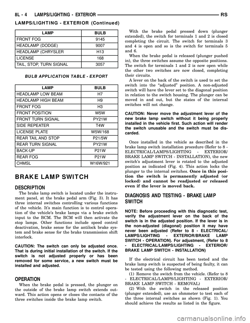
LAMP BULB
FRONT FOG 9145
HEADLAMP (DODGE) 9007
HEADLAMP (CHRYSLER H13
LICENSE 168
TAIL, STOP, TURN SIGNAL 3057
BULB APPLICATION TABLE - EXPORT
LAMP BULB
HEADLAMP LOW BEAM H7
HEADLAMP HIGH BEAM H9
FRONT FOG H3
FRONT POSITION W5W
FRONT TURN SIGNAL PY21W
SIDE REPEATER T4W
LICENSE PLATE W5W/168
REAR TAIL AND STOP P21/5W
REAR TURN SIGNAL PY21W
BACK-UP P21W
REAR FOG P21W
CHMSL W16W/921
BRAKE LAMP SWITCH
DESCRIPTION
The brake lamp switch is located under the instru-
ment panel, at the brake pedal arm (Fig. 3). It has
three internal switches controlling various functions
of the vehicle. It's main function is to control opera-
tion of the vehicle's brake lamps via a brake switch
input to the BCM. The BCM will then activate the
stop lamps. Other functions include speed control
deactivation, brake sense for the antilock brake sys-
tem and brake sense for the brake transmission shift
interlock.
CAUTION: The switch can only be adjusted once.
That is during initial installation of the switch. If the
switch is not adjusted properly or has been
removed for some service, a new switch must be
installed and adjusted.
OPERATION
When the brake pedal is pressed, the plunger on
the outside of the brake lamp switch extends out-
ward. This action opens or closes the contacts of the
three switches inside the brake lamp switch.With the brake pedal pressed down (plunger
extended), the switch for terminals 1 and 2 is closed
completing the circuit. The switch for terminals 3
and 4 is open and so is the switch for terminals 5
and 6.
When the brake pedal is released (plunger pushed
in), the three switches assume the opposite positions.
The switch for terminals 1 and 2 is now open while
the other two switches are now closed, completing
their circuits.
A lever on the back of the switch is used to set the
switch into the ªadjustedº position. A non-adjusted
switch will have the lever set to the diagonal position
in relation to the switch housing. The plunger can be
moved in and out, but the states of the internal
switches will not change.
CAUTION: Never move the adjustment lever of the
new brake lamp switch without it being properly
installed in the vehicle first. Such action will render
the switch unusable and the switch must be dis-
carded.
Once installed in the vehicle as described in the
brake lamp switch installation procedure (Refer to 8 -
ELECTRICAL/LAMPS/LIGHTING - EXTERIOR/
BRAKE LAMP SWITCH - INSTALLATION), the new
switch's adjustment lever is rotated to the adjusted
position as indicated (Fig. 4). This action locks the
plunger to the internal switches.Once in this posi-
tion the switch is permanently adjusted (or
locked) and cannot be readjusted or released
even if the lever is moved back.
DIAGNOSIS AND TESTING - BRAKE LAMP
SWITCH
NOTE: Before proceeding with this diagnostic test,
verify the adjustment lever on the back of the
switch is in the adjusted position. If the lever is in
the non-adjusted (diagonal) position it may have
never been adjusted (Refer to 8 - ELECTRICAL/
LAMPS/LIGHTING - EXTERIOR/BRAKE LAMP
SWITCH - OPERATION). For adjustment, (Refer to 8
- ELECTRICAL/LAMPS/LIGHTING - EXTERIOR/
BRAKE LAMP SWITCH - INSTALLATION)
If the electrical circuit has been tested and the
brake lamp switch is suspected of being faulty, it can
be tested using the following method.
(1) Remove the switch from the vehicle. (Refer to 8
- ELECTRICAL/LAMPS/LIGHTING - EXTERIOR/
BRAKE LAMP SWITCH - REMOVAL)
(2) With the switch in the released position
(plunger extended), use an ohmmeter to test each of
the three internal switches as shown (Fig. 1). You
should achieve the results as listed in the figure.
8L - 4 LAMPS/LIGHTING - EXTERIORRS
LAMPS/LIGHTING - EXTERIOR (Continued)
Page 390 of 2339

(3) Gently push the plunger on the brake lamp
switch in until it stops.
(4) With the switch in this depressed position
(plunger pushed in), use an ohmmeter to test each of
the three internal switches as shown (Fig. 2). You
should achieve the results as listed in the figure.
If you do not achieve the results as listed in both
figures, the switch is faulty and must be replaced.
Refer to Removal And Installation in this section.
If the switch is found to be operating properly, it
may be misadjusted. Do not reinstall the switch,
replace it. (Refer to 8 - ELECTRICAL/LAMPS/
LIGHTING - EXTERIOR/BRAKE LAMP SWITCH -
INSTALLATION)
CAUTION: The switch can only be adjusted once.
That is during initial installation of the switch. If the
switch is not adjusted properly or has beenremoved for any reason, a new switch must be
installed and adjusted.
REMOVAL
(1) Disconnect and isolate the battery negative
cable from its post on the battery.
(2) Remove silencer panel below steering column
and knee blocker.
(3) Remove the brake lamp switch by rotating the
switch in a counterclockwise direction approximately
30 degrees and pulling it out of the bracket (Fig. 3).
(4) Release the locking tab and disconnect the wir-
ing connector from the switch.
(5) Discard the brake lamp switch. It must not be
reused.
INSTALLATION
CAUTION: Do not reuse the original brake lamp
switch. The switch can only be adjusted once. That
is during initial installation of the switch. If the
switch is not adjusted properly or has been
removed for some service, a new switch must be
installed and adjusted.
(1) Mount and adjust the NEW brake lamp switch
using the following procedure:
(a) Connect the wiring connector to the switch
and latch the locking tab.
Fig. 1 SWITCH TEST - RELEASED POSITION
Fig. 2 SWITCH TEST - DEPRESSED POSITION
Fig. 3 Brake Lamp Switch And Pedal With Bracket
1 - BRAKE LAMP SWITCH
2 - WIRING CONNECTOR
3 - PEDAL AND BRACKET
RSLAMPS/LIGHTING - EXTERIOR8L-5
BRAKE LAMP SWITCH (Continued)
Page 407 of 2339
DOME/CARGO LAMP
REMOVAL
(1) Disconnect and isolate the battery negative
cable.
(2) Using a flat bladed tool, pry off the lamp lens.
(3) Remove bulb from lamp.
INSTALLATION
(1) Install bulb to lamp.
(2) Press lens into place.
(3) Connect battery negative cable.
GLOVE BOX LAMP SWITCH
REMOVAL
(1) Disconnect and isolate the battery negative
cable.
(2) Open glove box door.
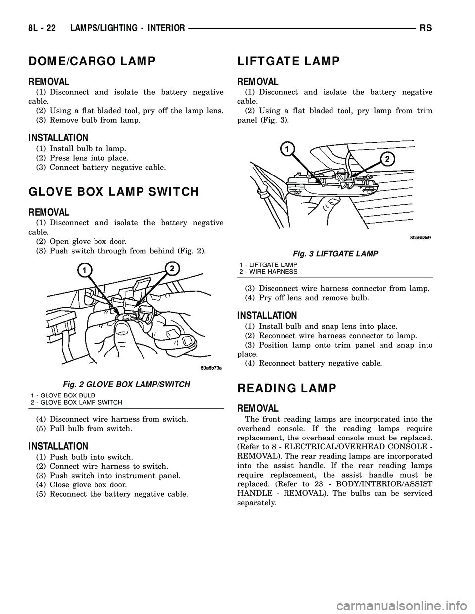
(3) Push switch through from behind (Fig. 2).
(4) Disconnect wire harness from switch.
(5) Pull bulb from switch.
INSTALLATION
(1) Push bulb into switch.
(2) Connect wire harness to switch.
(3) Push switch into instrument panel.
(4) Close glove box door.
(5) Reconnect the battery negative cable.
LIFTGATE LAMP
REMOVAL
(1) Disconnect and isolate the battery negative
cable.
(2) Using a flat bladed tool, pry lamp from trim
panel (Fig. 3).
(3) Disconnect wire harness connector from lamp.
(4) Pry off lens and remove bulb.
INSTALLATION
(1) Install bulb and snap lens into place.
(2) Reconnect wire harness connector to lamp.
(3) Position lamp onto trim panel and snap into
place.
(4) Reconnect battery negative cable.
READING LAMP
REMOVAL
The front reading lamps are incorporated into the
overhead console. If the reading lamps require
replacement, the overhead console must be replaced.
(Refer to 8 - ELECTRICAL/OVERHEAD CONSOLE -
REMOVAL). The rear reading lamps are incorporated
into the assist handle. If the rear reading lamps
require replacement, the assist handle must be
replaced. (Refer to 23 - BODY/INTERIOR/ASSIST
HANDLE - REMOVAL). The bulbs can be serviced
separately.
Fig. 2 GLOVE BOX LAMP/SWITCH
1 - GLOVE BOX BULB
2 - GLOVE BOX LAMP SWITCH
Fig. 3 LIFTGATE LAMP
1 - LIFTGATE LAMP
2 - WIRE HARNESS
8L - 22 LAMPS/LIGHTING - INTERIORRS
Page 413 of 2339
SELF-DIAGNOSTIC TEST
A self-diagnostic test is used to determine that the
electronics module is operating properly, and that all
the PCI data bus messages are being received for ini-
tial operation. Initiate the self-diagnostic test as fol-
lows:
(1) With the ignition switch in the Off position, on
Electronic Vehicle Information Center (EVIC) and
Compass Mini-Trip Computer (CMTC) equipped vehi-
cles simultaneously depress and hold theSTEPand
theRESETbuttons. On Compass Temperature Mod-
ule (CT) equipped vehicles depress theC/Tand the
US/Mpush buttons.
(2) Turn the ignition switch to the On position.
(3) Following completion of these tests, the elec-
tronics module will display one of the following mes-
sages:
a.Pass Self Test (EVIC only), PASS (CT,
CMTC)- The electronics module is working properly.
b.Failed Self Test (EVIC only), FAIL (CT,
CMTC)- The electronics module has an internal fail-
ure. The electronics module is faulty and must be
replaced.
NOTE: If the compass functions, but accuracy is
suspect, it may be necessary to perform a variation
adjustment. This procedure allows the compass
unit to accommodate variations in the earth's mag-
netic field strength, based on geographic location.
(Refer to 8 - ELECTRICAL/OVERHEAD CONSOLE -
STANDARD PROCEDURE - COMPASS VARIATION
ADJUSTMENT).
NOTE: If the compass reading display is blank and
only ªCALº appears in the display, demagnetizing
may be necessary to remove excessive residual
magnetic fields from the vehicle. (Refer to 8 - ELEC-
TRICAL/OVERHEAD CONSOLE - STANDARD PRO-
CEDURE - COMPASS DEMAGNETIZING).
STANDARD PROCEDURE
COMPASS CALIBRATION
CAUTION: Do not place any external magnets, such
as magnetic roof mount antennas, in the vicinity of
the compass. Do not use magnetic tools when ser-
vicing the overhead console.The electronic compass unit features a self-cali-
brating design, which simplifies the calibration pro-
cedure. This feature automatically updates the
compass calibration while the vehicle is being driven.
This allows the compass unit to compensate for small
changes in the residual magnetism the vehicle may
acquire during normal use. If the compass readings
appear to be erratic or out of calibration, perform the
following calibration procedure. Also, new service
replacement Electronic Modules (EVIC, CMTC, CT)
must have their compass calibrated using this proce-
dure. Do not attempt to calibrate the compass near
large metal objects such as other vehicles, large
buildings, or bridges; or, near overhead or under-
ground power lines.
NOTE: Whenever the compass is calibrated manu-
ally, the variance number must also be reset. (Refer
to 8 - ELECTRICAL/OVERHEAD CONSOLE - STAN-
DARD PROCEDURE - COMPASS VARIATION
ADJUSTMENT).
Calibrate the compass manually as follows:
(1) Turn the ignition switch to the On position. If
the compass/thermometer data is not currently being
displayed, momentarily depress and release the C/T
push button to reach the compass/thermometer dis-
play.
(2) On Electronic Vehicle Information Center
(EVIC) and Compass Mini-Trip Computer (CMTC)
equipped vehicles depress the Reset push button and
hold the button until ªCALº appears in the display.
This takes about ten seconds, and appears about five
seconds after ªVAR = XXº is displayed. On Compass
Temperature Module (CT) equipped vehicles depress
the C/T push button and US/M push button down
until ªCALº appears in the display. This takes about
ten seconds, and appears about five seconds after
ªVAR = XXº is displayed.
(3) Release the push button(s).
(4) Drive the vehicle on a level surface, away from
large metal objects and power lines, through three or
more complete circles at between five and eight kilo-
meters-per-hour (three and five miles-per-hour) for a
minimum of 48 seconds. The ªCALº message will dis-
appear from the display to indicate that the compass
is now calibrated.
NOTE: If the ªCALº message remains in the display,
either there is excessive magnetism near the com-
pass, or the unit is faulty. Repeat the calibration
procedure one more time.
8M - 4 OVERHEAD CONSOLERS
OVERHEAD CONSOLE (Continued)
Page 416 of 2339
(2) Connect the EVIC, CMTC or CT electronic
module and the reading/courtesy lamps electrical
connector.
(3) Using your fingertips, grasp the sides of the
overhead console and push straight up evenly to
engage the two snap clips at the rear of the unit.
CAUTION: DO NOT PRESS ON THE SUNGLASS
STORAGE BIN DOOR. DAMAGE TO THE DOOR MAY
RESULT.
(4) Install the overhead console retaining screw,
located in the front of console. Torque the screw to
1.2 N´m (10 in. lbs.).
(5) Connect the remote negative battery cable.
SPECIAL TOOLS
OVERHEAD CONSOLE
ELECTRONIC VEHICLE INFO
CENTER
DESCRIPTION
The Electronic Vehicle Information Center (EVIC)
is located in the overhead console. The EVIC features
a large Vacuum Fluorescent Display (VFD) screen for
displaying information, and back-lit push button
switches labeled C/T (compass/thermometer), RESET,
STEP, and MENU. The EVIC module contains a cen-
tral processing unit and interfaces with other elec-
tronic modules in the vehicle over the Programmable
Communications Interface (PCI) data bus circuit.
The EVIC ªMenuº push button provides the vehicle
operator with a user interface, which allows the
selection of several optional customer programmable
electronic features to suit individual preferences.
(Refer to 8 - ELECTRICAL/OVERHEAD CONSOLE/
ELECTRONIC VEHICLE INFO CENTER - STAN-
DARD PROCEDURE - ELECTRONIC VEHICLE
INFORMATION CENTER PROGRAMMING).
If the vehicle is equipped with the optional univer-
sal transmitter transceiver, the EVIC will also dis-
play messages and an icon indicating when the
universal transmitter transceiver is being trained,
which of the three transmitter buttons is transmit-
ting, and when the transceiver is cleared.Data input for all EVIC functions, including VFD
dimming level, is received through the PCI data bus
circuit. The EVIC module uses its internal program-
ming and all of its data inputs to calculate and dis-
play the requested data. If the data displayed is
incorrect, perform the SELF - DIAGNOSTIC TEST
(Refer to 8 - ELECTRICAL/OVERHEAD CONSOLE -
DIAGNOSIS AND TESTING). If these tests prove
inconclusive, the use of a DRBIIItscan tool and the
proper diagnostic procedures information are recom-
mended for further testing of the EVIC module and
the PCI data bus circuit.
The EVIC module cannot be repaired, and is avail-
able for service only as a unit. This unit includes the
plastic module and display lens. If any of these com-
ponents is faulty or damaged, the complete EVIC
module must be replaced.
OPERATION
The Electronic Vehicle Information Center (EVIC)
uses both non-switched and ignition switched sources
of battery current so that some of its features remain
operational at any time, while others may only oper-
ate with the ignition switch in the On position. When
the ignition switch is turned to the On position, the
EVIC module Vacuum Fluorescent Display (VFD)
will return to the last function being displayed before
the ignition was turned to the Off position.
The compass/thermometer display is the normal
EVIC display. With the ignition switch in the On
position, momentarily depressing and releasing the
C/T (compass/thermometer) push button switch will
cause the EVIC to return to the compass/thermome-
ter/trip computer display mode from any other mode.
While in the compass/thermometer/trip computer dis-
play mode, momentarily depressing and releasing the
Step push button will step through the available trip
computer display options.
The EVIC trip computer features several functions
that can be reset. The functions that can be reset
are:
²Average fuel economy
²Trip odometer
²Elapsed time
With the ignition switch in the On position and
with one of the functions of the trip computer that
can be reset currently displayed, depressing the
Reset push button twice within four seconds will per-
form a global reset, and all of the trip computer
information that can be reset will be reset to zero.
With the ignition switch in the On position and the
function that is to be reset currently displayed,
momentarily depressing and holding the Reset push
button for one second will perform a local reset, and
only the value of the displayed function will be reset
to zero. A global or local reset will only occur if the
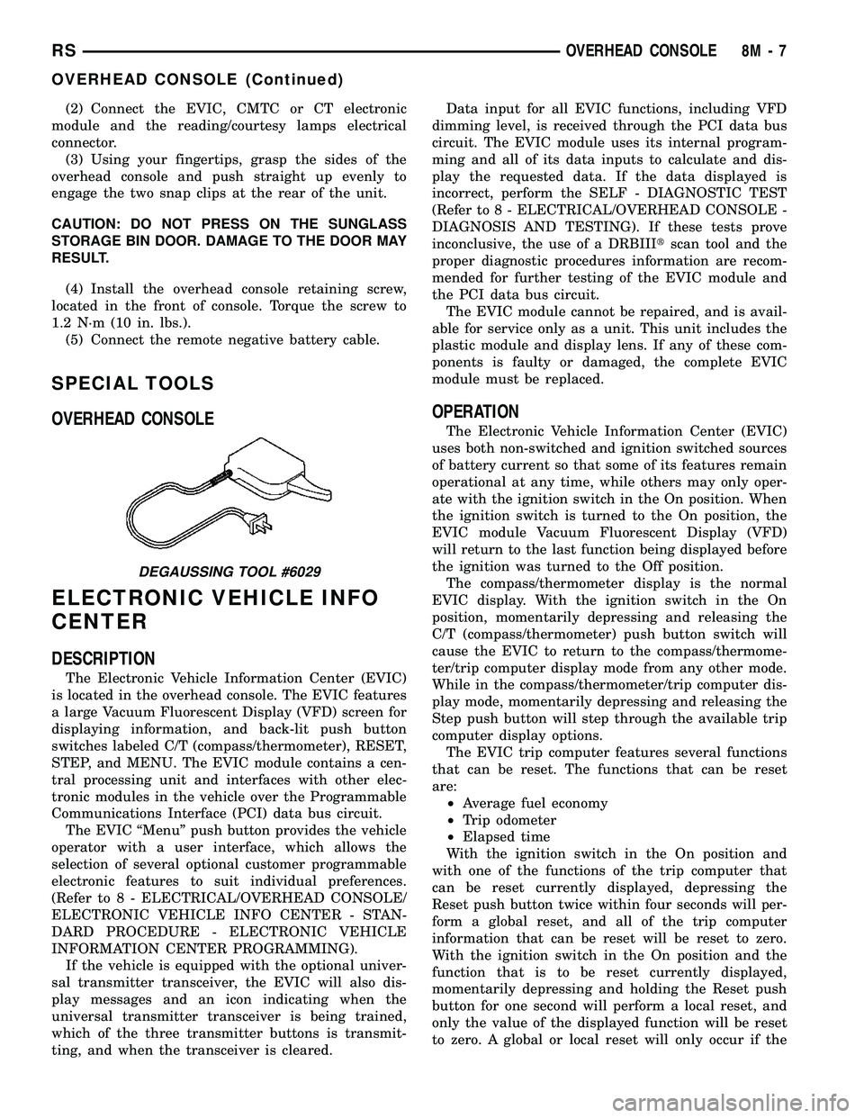
DEGAUSSING TOOL #6029
RSOVERHEAD CONSOLE8M-7
OVERHEAD CONSOLE (Continued)
Page 417 of 2339
function currently displayed is a function that can be
reset. The distance to service function can also be
reset using the local reset method, but it will reset
back to the Service Interval distance that is set in
the EVIC programmable features mode. (Refer to 8 -
ELECTRICAL/OVERHEAD CONSOLE/ELEC-
TRONIC VEHICLE INFO CENTER - STANDARD
PROCEDURE).
DIAGNOSIS AND TESTING
ELECTRONIC VEHICLE INFORMATION CENTER
Electronic Vehicle Information Center (EVIC) data
is obtained from the Body Control Module (BCM) on
the Programmable Communications Interface (PCI)
Data Bus circuit. The EVIC will display dashes (- -)
for any of the screens it did not receive the bus mes-
sages. The label corresponding to the missing infor-
mation will be lit. If no EVIC data is displayed,
check the PCI Data Bus circuit communications and
the BCM. If the dimming level is improper check the
PCI Data Bus circuit.
The use of a DRBIIItscan tool and the proper
diagnostic procedures information are recommended
for further testing of the EVIC module and the PCI
data bus circuit. Perform the SELF-DIAGNOSTIC
TEST before replacing the EVIC module (Refer to 8 -
ELECTRICAL/OVERHEAD CONSOLE - DIAGNO-
SIS AND TESTING).
STANDARD PROCEDURE
ELECTRONIC VEHICLE INFORMATION CENTER
PROGRAMMING
EVIC PROGRAMMING MODE
Some vehicles are equipped with a Electronic Vehi-
cle Information Center (EVIC) equipped overhead
console. The Electronic Vehicle Information Center
(EVIC) provides the vehicle operator with a user
interface, which allows the selection of several
optional customer programmable electronic features
to suit individual preferences. The EVIC must be
placed into its programming mode in order to view or
change the programmable features. To enter the
EVIC programming mode and to view or change the
selected programmable features options, proceed as
follows:
(1) Turn the ignition switch to the On position.
(2) Depress and release the Menu push button.
The first item in the programmable features menu
list will appear in the EVIC display.(3) Momentarily depress and release the Menu
push button to step through the programmable fea-
tures list. Each programmable feature and its cur-
rently selected option will appear on the EVIC
display in the sequence shown in the Programmable
Features list that follows.
(4) Momentarily depress and release the Step push
button to step through the available options for the
programmable feature being displayed.
(5) The option that last appears in the display
with a programmable feature before exiting the pro-
gramming mode, becomes the newly selected pro-
grammable feature option.
(6) The EVIC exits the programming mode and
returns to its normal operating mode when the C/T
push button is depressed or when the end of the pro-
grammable features menu list is reached, whichever
occurs first.
PROGRAMMABLE FEATURES
NOTE: Tire pressure monitoring (TPM) system infor-
mation is not covered in this section of the service
manual. Refer to the tires/wheels section of this
manual for detailed tire pressure monitoring system
information.
²LANGUAGE?- The options include English,
Francaise, Deutsch, Italiana, or Espanol. The default
is English. All EVIC display nomenclature, including
the trip computer functions, warning messages and
the programmable features appear in the selected
language.
²DISPLAY U.S. OR METRIC?- The options
include U.S. and M. The default is U.S. This feature
toggles the trip computer temperature, fuel economy
and odometer display readings between U.S. and
metric units of measure. It also changes the odome-
ter display in the instrument cluster.
²SERVICE INTV. =- The options include from
3200 to 12000 kilometers in 800 kilometer incre-
ments (2000 to 7500 miles in 500 mile increments).
The default is 12000 kilometers (7500 miles). The
selected distance becomes the interval at which the
Perform Service warning message will be displayed
by the EVIC. If a new distance is selected, a second
programmable feature appears,RESET SERVICE
DISTANCE?- The options include No and Yes. The
default is Yes. When Yes is selected, the accumulated
distance since the last previous Perform Service
warning message will be reset to zero because the
service interval has been changed. When No is
selected, the distance until the next Perform Service
warning message is reduced by the accumulated dis-
tance since the last previous message.
8M - 8 OVERHEAD CONSOLERS
ELECTRONIC VEHICLE INFO CENTER (Continued)
Page 420 of 2339
NOTE: If a new CMTC module has been installed,
the compass will have to be calibrated and the vari-
ance set. (Refer to 8 - ELECTRICAL/OVERHEAD
CONSOLE - STANDARD PROCEDURE - COMPASS
CALIBRATION).
UNIVERSAL TRANSMITTER
DESCRIPTION
A Universal Transmitter transceiver is available on
some vehicles. The universal transmitter transceiver
is integral to the Electronic Vehicle Information Cen-
ter (EVIC) and the Compass Mini-Trip Computer
(CMTC) modules, which are located in the overhead
console. The only visible component of the universal
transmitter are the three transmitter push buttons
centered between the modules push buttons located
just rearward of the display screen in the overhead
console. The three universal transmitter push but-
tons are identified with one, two or three light indi-
cators so that they can be easily identified.
Each of the three universal transmitter push but-
tons controls an independent radio transmitter chan-
nel. Each of these three channels can be trained to
transmit a different radio frequency signal for the
remote operation of garage door openers, motorized
gate openers, home or office lighting, security sys-
tems or just about any other device that can be
equipped with a radio receiver in the 286 to 399
MegaHertz (MHz) frequency range for remote opera-
tion. The universal transmitter is capable of operat-
ing systems using either rolling code or non-rolling
code technology.
The electronics module displays messages and a
small house-shaped icon with one, two or three dots
corresponding to the three transmitter buttons to
indicate the status of the universal transmitter. The
EVIC messages are:
²Cleared Channels- Indicates that all of the
transmitter codes stored in the universal transmitter
have been successfully cleared.
²Training- Indicates that the universal trans-
mitter is in its transmitter learning mode.
²Trained- Indicates that the universal transmit-
ter has successfully acquired a new transmitter code.
²Transmit- Indicates that a trained universal
transmitter button has been depressed and that the
universal transmitter is transmitting.
The universal transmitter cannot be repaired, and
is available for service only as a unit with the EVIC
or CMTC modules. If any of these components is
faulty or damaged, the complete EVIC or CMTC
module must be replaced.
DIAGNOSIS AND TESTING
UNIVERSAL TRANSMITTER
If both the Universal Transmitter and the Elec-
tronic Vehicle Information Center (EVIC) are inoper-
ative, (Refer to 8 - ELECTRICAL/OVERHEAD
CONSOLE/ELECTRONIC VEHICLE INFO CENTER
- DIAGNOSIS AND TESTING). If the Universal
Transmitter is inoperative, but the EVIC is operating
normally, retrain the Transmitter with a known good
transmitter (Refer to 8 - ELECTRICAL/OVERHEAD
CONSOLE/UNIVERSAL TRANSMITTER - STAN-
DARD PROCEDURE - SETTING TRANSMITTER
CODES). If the unit is still inoperative, test the uni-
versal transmitter with the Radio Frequency Detec-
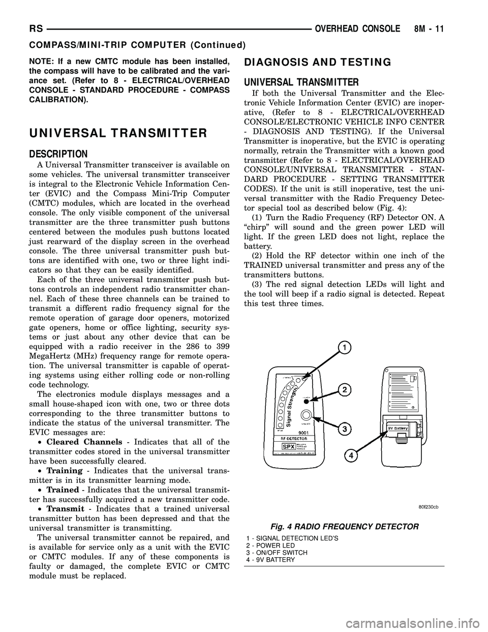
tor special tool as described below (Fig. 4):
(1) Turn the Radio Frequency (RF) Detector ON. A
ªchirpº will sound and the green power LED will
light. If the green LED does not light, replace the
battery.
(2) Hold the RF detector within one inch of the
TRAINED universal transmitter and press any of the
transmitters buttons.
(3) The red signal detection LEDs will light and
the tool will beep if a radio signal is detected. Repeat
this test three times.
Fig. 4 RADIO FREQUENCY DETECTOR
1 - SIGNAL DETECTION LED'S
2 - POWER LED
3 - ON/OFF SWITCH
4 - 9V BATTERY
RSOVERHEAD CONSOLE8M-11
COMPASS/MINI-TRIP COMPUTER (Continued)
Page 426 of 2339

travel is accomplished by hall effect sensors, drive
motor speed and pinch sensors (tape switches).
Anytime the liftgate is opened or closed using the
power liftgate system the power liftgate control mod-
ule learns from the cycle. If a replacement power lift-
gate component is installed or a liftgate adjustment
is made, the module will relearn the effort and/or
time required to open or close the liftgate. This learn
cycle can be performed with a DRB IIIt, or equiva-
lent scan tool, or with a complete cycle of the liftgate,
using any one of the command switches. (Refer to 8 -
ELECTRICAL/POWER DOORS - STANDARD PRO-
CEDURE) for detailed instructions.
The power liftgate system is designed with a num-
ber of system inhibitors. These inhibitors are neces-
sary for safety and / or feasibility of the power
liftgate system. The power liftgate system inhibitors
are:
²The Power Liftgate may not operate in extreme
temperatures. These extreme temperatures will be
approximately less than -12É F (-24.4É C) or greater
than 143É F (61.6É C). A chime/thermister assembly
in the rear light bar assembly monitors the outside
temperature.
²The vehicle transmission must be in Park or
Neutral for the power liftgate to start a cycle.
²If multiple obstacles are detected during the
same power open or close cycle, the liftgate goes into
manual operation.
²If severe problems occur, Diagnostic Trouble
Codes (DTC) are stored in the power liftgate control
module.
POWER LIFTGATE SYSTEM CAUTIONS AND
WARNINGS
WARNING: ALWAYS DISCONNECT THE BATTERY
NEGATIVE CABLE BEFORE ATTEMPTING ANY
POWER LIFTGATE SYSTEM SERVICE.
WARNING: THERE IS A SMALL AREA ON BOTH
SIDES OF THE LOWER POWER LIFTGATE WHICH
IS NOT PROTECTED BY PINCH SENSORS.
EXTREME CARE MUST BE TAKEN TO PREVENT
OBJECTS FROM ENTERING THIS AREA ONCE THELIFTGATE REACHES THE SECONDARY LATCH
CONTACT (APPROXIMATELY 1/2 INCH BEFORE
FULLY CLOSED).
WARNING: NEVER ATTEMPT TO ENTER OR EXIT
THE VEHICLE WITH THE LIFTGATE IN MOTION.
YOU COULD DAMAGE THE POWER LIFTGATE SYS-
TEM AND/OR COMPONENTS AND/OR CAUSE PER-
SONAL INJURY.
WARNING: NEVER STICK OBJECTS IN THE POWER
LIFTGATE WHEN CINCHING CLOSED. YOU COULD
DAMAGE THE VEHICLE, POWER LIFTGATE SYS-
TEM COMPONENTS AND/OR CAUSE PERSONAL
INJURY.
DIAGNOSIS AND TESTING
POWER LIFTGATE SYSTEM
The power liftgate system contains many compo-
nents and modules. In order to obtain conclusive
testing the Programmable Communications Interface
(PCI) data bus network and all of the electronic mod-
ules that provide inputs to, or receive outputs from
the power liftgate system must be checked.
The power liftgate system can be diagnosed with
an appropriate scan tool, such as the DRB IIItor
equivalent. The DRB IIItcan be used to observe var-
ious switch statuses throughout the power liftgate
system to help diagnose an inoperative switch or
component. The DRB IIItcan also be used to actuate
various components throughout the power liftgate
system to help diagnose an inoperative component.
Before any testing of the power liftgate system is
attempted, the battery should be fully charged, all
built-in power liftgate system inhibitors read and
understood, and all wire harness and ground connec-
tions inspected around the affected areas on the vehi-
cle.
The following are quick reference diagnostic tables
to help when diagnosing and testing the power lift-
gate system.
RSPOWER LIFTGATE SYSTEM8N-3
POWER LIFTGATE SYSTEM (Continued)
Page 431 of 2339

STANDARD PROCEDURE
LIFTGATE ADJUSTMENT
In order for the power liftgate system to function
properly the liftgate must move freely and smoothly.
The power liftgate system can accommodate for some
minor changes in the effort required to move the lift-
gate. However, in extreme conditions the liftgate may
need to be mechanically adjusted for proper fit and
finish. (Refer to 23 - BODY/DECKLID/HATCH/LIFT-
GATE/TAILGATE/LIFTGATE - INSTALLATION) for
detailed instructions.
If a problem exists with the power liftgate and it is
suspected to be extreme effort, check the liftgate prop
rods and hinges for free movement.
NOTE: Routine application of Mopar MP-50Tor
equivalent on the chrome prop rod shafts and lift-
gate latch and hinges will help keep the liftgate in
good working order.
POWER LIFTGATE LEARN CYCLE
Any time a power liftgate component is removed,
replaced or a liftgate adjustment is performed a learn
cycle must be performed. This learn cycle enables the
power liftgate control module to learn or relearn
information (travel limits, resistance to door travel,
etc.) which allows it to perform properly and safely.
Perform the following to complete a power liftgate
learn cycle:
(1) Obtain a DRBIIIt, or equivalent scan tool.
(2) Connect the scan tool to the vehicle and check
for any power liftgate system stored Diagnostic Trou-
ble Codes (DTCs), correct and erase any stored
DTCs.
(3) Using the scan tool, Go into Test Routine Menu
and select the power open command.
(4) Select the power close command.
(5) The liftgate learn cycle is complete.
If a DRBIIItor equivalent scan tool is not avail-
able, the learn cycle can be performed by actuating
the liftgate using any of the normal command
switches. Be certain to cycle the liftgate through a
complete open and close cycle before returning the
vehicle to service.
NOTE: If the power liftgate will not complete a full
cycle a problem exists with the power liftgate sys-
tem. (Refer to 8 - ELECTRICAL/POWER DOORS -
DIAGNOSIS AND TESTING).
CHIME/THERMISTOR
DESCRIPTION
The chime/thermistor assembly is a small capacitor
shaped electrical component mounted to the rear
license plate lamp housing assembly (Fig. 2) , located
just above the license plate. The chime portion of the
assembly controls the audible chime sound heard at
the rear of the vehicle when the power liftgate is in
motion. The thermistor portion of the assembly is a
temperature sensor, used by the power liftgate con-
trol module. The chime/thermistor assembly is a ser-
viceable component.
OPERATION
The chime/thermistor assembly performs two dif-
ferent functions for the power liftgate system. First,
the chime portion provides an audible chime sound
which is controlled by the power liftgate control mod-
ule. The chime/thermistor assembly is hardwired to
the power liftgate control module. Second the ther-
mistor provides a outside temperature reading by
way of a resistance reading supplied to the power
liftgate control module. As temperature increases the
resistance reading increases, as temperature
decreases the resistance reading decreases.
REMOVAL
(1) Disconnect and isolate the battery negative
cable.
Fig. 2 REAR LIGHT BAR
1 - CHIME / THERMISTOR
2 - ELECTRIC RELEASE HANDLE SWITCH
3 - LICENSE PLATE LAMPS
8N - 8 POWER LIFTGATE SYSTEMRS
POWER LIFTGATE SYSTEM (Continued)
Page 432 of 2339

(2) Remove the rear light bar assembly from the
vehicle. (Refer to 8 - ELECTRICAL/POWER DOORS/
SWITCH - REMOVAL) for the procedure.
(3) Grasp the light bar at its sides next to ther-
mistor/chime assembly and gently pull the two sides
of the light bar apart until the thermistor/chime
assembly can be removed.
INSTALLATION
(1) Gently pull the two sides of the light bar apart
until the thermistor/chime assembly can be installed.
(2) Install the rear light bar assembly on the vehi-
cle. (Refer to 8 - ELECTRICAL/POWER DOORS/
SWITCH - INSTALLATION) for the procedure.
(3) Connect the battery negative cable.
ENGAGE ACTUATOR
DESCRIPTION
The 12 volt engage actuator (Fig. 3) provides the
engagement and disengagement of the liftgate gear
motor to the lift gear by way of an over center link,
activated by a lever.
The engage actuator is a serviceable component
and cannot be repaired, if found to be inoperative it
must be replaced.
OPERATION
The engage actuators normal position is disen-
gaged. When a power liftgate open or close command
is generated from any of the command switches, the
power liftgate control module signals the engage
actuator to move its lever to the engaged position.
This engages the gear motor to the lift gear, so when
the motor turns the lift gate moves upward or down-
wards depending on its current position.
During a manual liftgate open or close cycle the
engage actuator is disengaged, allowing unrestricted
liftgate movement.
REMOVAL
(1) Disconnect and isolate the battery negative
cable.
(2) Remove the left rear D-pillar trim from the
vehicle, (Refer to 23 - BODY/INTERIOR/LEFT
D-PILLAR TRIM PANEL - REMOVAL).
(3) Manually engage the actuator link rod, this
must be done to access one of the engage actuator
retaining screws.
(4) Remove the two engage actuator retaining
screws (Fig. 4).
(5) Disconnect the engage actuator electrical con-
nector and remove the engage actuator from the
vehicle.
Fig. 3 LIFTGATE GEAR MOTOR ASSEMBLY
1 - TRANSVERSE BRACKET
2 - ENGAGE ACTUATOR
3 - LIFT GEAR AND ROD ASSEMBLY
4 - LIFTGATE MOTOR
Fig. 4 LIFTGATE GEAR MOTOR ASSEMBLY
1 - ENGAGE ACTUATOR RETAINING SCREWS
2 - LIFT GEAR RETAINING BOLTS
RSPOWER LIFTGATE SYSTEM8N-9
CHIME/THERMISTOR (Continued)