service CHRYSLER VOYAGER 2005 Service Manual
[x] Cancel search | Manufacturer: CHRYSLER, Model Year: 2005, Model line: VOYAGER, Model: CHRYSLER VOYAGER 2005Pages: 2339, PDF Size: 59.69 MB
Page 338 of 2339
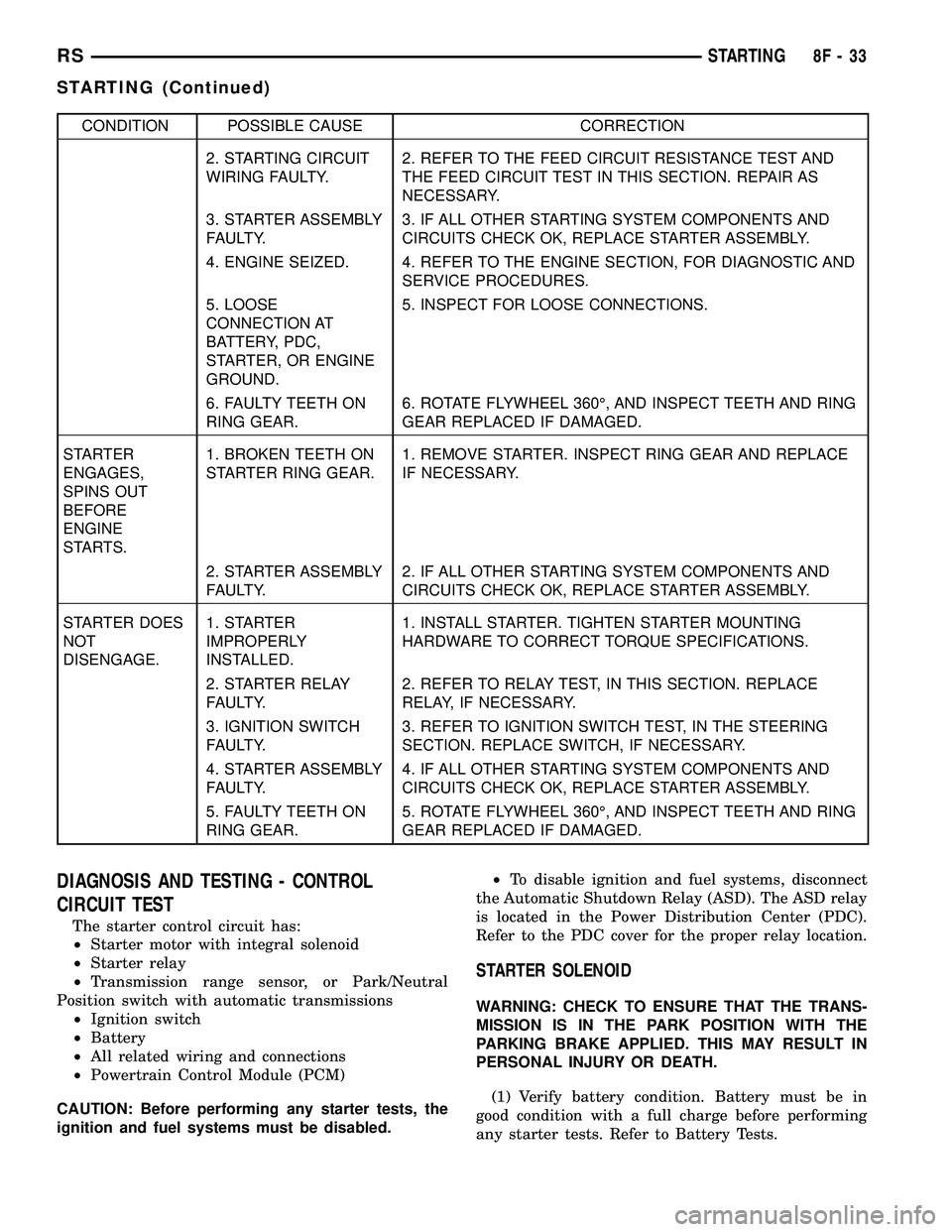
CONDITION POSSIBLE CAUSE CORRECTION
2. STARTING CIRCUIT
WIRING FAULTY.2. REFER TO THE FEED CIRCUIT RESISTANCE TEST AND
THE FEED CIRCUIT TEST IN THIS SECTION. REPAIR AS
NECESSARY.
3. STARTER ASSEMBLY
FAULTY.3. IF ALL OTHER STARTING SYSTEM COMPONENTS AND
CIRCUITS CHECK OK, REPLACE STARTER ASSEMBLY.
4. ENGINE SEIZED. 4. REFER TO THE ENGINE SECTION, FOR DIAGNOSTIC AND
SERVICE PROCEDURES.
5. LOOSE
CONNECTION AT
BATTERY, PDC,
STARTER, OR ENGINE
GROUND.5. INSPECT FOR LOOSE CONNECTIONS.
6. FAULTY TEETH ON
RING GEAR.6. ROTATE FLYWHEEL 360É, AND INSPECT TEETH AND RING
GEAR REPLACED IF DAMAGED.
STARTER
ENGAGES,
SPINS OUT
BEFORE
ENGINE
STARTS.1. BROKEN TEETH ON
STARTER RING GEAR.1. REMOVE STARTER. INSPECT RING GEAR AND REPLACE
IF NECESSARY.
2. STARTER ASSEMBLY
FAULTY.2. IF ALL OTHER STARTING SYSTEM COMPONENTS AND
CIRCUITS CHECK OK, REPLACE STARTER ASSEMBLY.
STARTER DOES
NOT
DISENGAGE.1. STARTER
IMPROPERLY
INSTALLED.1. INSTALL STARTER. TIGHTEN STARTER MOUNTING
HARDWARE TO CORRECT TORQUE SPECIFICATIONS.
2. STARTER RELAY
FAULTY.2. REFER TO RELAY TEST, IN THIS SECTION. REPLACE
RELAY, IF NECESSARY.
3. IGNITION SWITCH
FAULTY.3. REFER TO IGNITION SWITCH TEST, IN THE STEERING
SECTION. REPLACE SWITCH, IF NECESSARY.
4. STARTER ASSEMBLY
FAULTY.4. IF ALL OTHER STARTING SYSTEM COMPONENTS AND
CIRCUITS CHECK OK, REPLACE STARTER ASSEMBLY.
5. FAULTY TEETH ON
RING GEAR.5. ROTATE FLYWHEEL 360É, AND INSPECT TEETH AND RING
GEAR REPLACED IF DAMAGED.
DIAGNOSIS AND TESTING - CONTROL
CIRCUIT TEST
The starter control circuit has:
²Starter motor with integral solenoid
²Starter relay
²Transmission range sensor, or Park/Neutral
Position switch with automatic transmissions
²Ignition switch
²Battery
²All related wiring and connections
²Powertrain Control Module (PCM)
CAUTION: Before performing any starter tests, the
ignition and fuel systems must be disabled.²To disable ignition and fuel systems, disconnect
the Automatic Shutdown Relay (ASD). The ASD relay
is located in the Power Distribution Center (PDC).
Refer to the PDC cover for the proper relay location.
STARTER SOLENOID
WARNING: CHECK TO ENSURE THAT THE TRANS-
MISSION IS IN THE PARK POSITION WITH THE
PARKING BRAKE APPLIED. THIS MAY RESULT IN
PERSONAL INJURY OR DEATH.
(1) Verify battery condition. Battery must be in
good condition with a full charge before performing
any starter tests. Refer to Battery Tests.
RSSTARTING8F-33
STARTING (Continued)
Page 352 of 2339
HEATED SEAT SYSTEM
TABLE OF CONTENTS
page page
HEATED SEAT SYSTEM
DESCRIPTION..........................7
OPERATION............................8
DIAGNOSIS AND TESTING
HEATED SEAT SYSTEM.................8
HEATED SEAT SWITCH
DESCRIPTION..........................8
OPERATION............................9
DIAGNOSIS AND TESTING
DRIVER HEATED SEAT SWITCH..........9
REMOVAL.............................10
INSTALLATION.........................10HEATED SEAT ELEMENTS
DESCRIPTION.........................11
OPERATION...........................11
DIAGNOSIS AND TESTING
HEATED SEAT ELEMENTS..............11
REMOVAL.............................12
INSTALLATION.........................12
HEATED SEAT SENSOR
DESCRIPTION.........................13
OPERATION...........................13
DIAGNOSIS AND TESTING
HEATED SEAT SENSOR................13
HEATED SEAT SYSTEM
DESCRIPTION
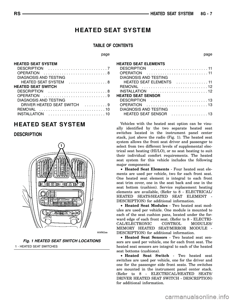
Vehicles with the heated seat option can be visu-
ally identified by the two separate heated seat
switches located in the instrument panel center
stack, just above the radio (Fig. 1). The heated seat
system allows the front seat driver and passenger to
select from two different levels of supplemental elec-
trical seat heating (HI/LO), or no seat heating to suit
their individual comfort requirements. The heated
seat system for this vehicle includes the following
major components:
²Heated Seat Elements- Four heated seat ele-
ments are used per vehicle, two for each front seat.
One heated seat element is integral to each front
seat trim cover, one in the seat back and one in the
seat bottom (cushion). Service replacement heating
elements are available, (Refer to 8 - ELECTRICAL/
HEATED SEATS/HEATED SEAT ELEMENT -
DESCRIPTION) for additional information.
²Heated Seat Modules- Two heated seat mod-
ules are used per vehicle. One module is mounted to
each of the seat cushion pans, located under the for-
ward edge of each front seat. (Refer to 8 - ELECTRI-
CAL/ELECTRONIC CONTROL MODULES/
MEMORY HEATED SEAT/MIRROR MODULE -
DESCRIPTION) for additional information.
²Heated Seat Sensors- Two heated seat sen-
sors are used per vehicle, one for each front seat. The
heated seat sensors are integral to each of the heated
seat bottoms (cushions).
²Heated Seat Switch- Two heated seat
switches are used per vehicle, one for the driver and
one for the passenger side front seats. The switches
are mounted in the instrument panel center stack.
(Refer to 8 - ELECTRICAL/HEATED SEATS/
DRIVER HEATED SEAT SWITCH - DESCRIPTION)
for additional information.
Fig. 1 HEATED SEAT SWITCH LOCATIONS
1 - HEATED SEAT SWITCHES
RSHEATED SEAT SYSTEM8G-7
Page 354 of 2339
OPERATION
There are three positions that can be selected with
each of the heated seat switches: Off, Low, or High.
When the left side of the switch rocker is fully
depressed, the Low position is selected and the low
position LED indicator illuminates. When the right
side of the switch rocker is fully depressed, the High
position is selected and the high position LED indi-
cator illuminates. When the switch rocker is moved
to its neutral position (middle), Off is selected and
both LED indicators are extinguished.
Each switch provides separate resistor, hard wire
inputs to its respective Heated Seat Module (HSM) to
indicate the selected switch position. The heated seat
module responds to the heated seat switch status
messages by controlling the output to the seat heater
elements of the selected seat. The Low heat position
set point is about 36É C (97É F), and the High heat
position set point is about 41É C (105É F).
DIAGNOSIS AND TESTING
DRIVER HEATED SEAT SWITCH
Refer to the appropriate wiring information for
complete circuit schematic or connector pin-out infor-
mation.
WARNING: REFER TO THE RESTRAINTS SECTION
OF THIS MANUAL BEFORE ATTEMPTING ANY
STEERING WHEEL, STEERING COLUMN, SEAT OR
INSTRUMENT PANEL COMPONENT DIAGNOSIS OR
SERVICE. FAILURE TO TAKE THE PROPER PRE-
CAUTIONS COULD RESULT IN ACCIDENTAL AIR-
BAG DEPLOYMENT AND POSSIBLE PERSONAL
INJURY.
CHECKING SWITCH SIGNAL AND WIRING AT THE
MODULE
(1) Disconnect and isolate the battery negative
cable.
(2) Access and disconnect the gray 4-way connector
from the heated seat module. Visually inspect wiring
terminals for damage that would prevent positive
connection. If not OK, repair or replace the necessary
components.(3) Connect the battery negative cable. Place the
heated seat switch in the LO position. Using an
Ohmmeter, check the resistance between cavities 2
and 3 of the gray connector noted above. Resistance
should be about 3.5 kilohms (3500 ohms). If not OK,
check resistance directly at switch, as noted below. If
OK, proceed to the next step. If not OK, replace the
faulty switch.
(4) Place the heated seat switch in the HI position.
Using an ohmmeter, check the resistance between
cavities 2 and 3 of the gray connector noted above.
Resistance should be about 1.4 kilohms (1400 ohms).
If not OK, check resistance directly at the switch, as
indicated in the Heated Seat Switch Test Table. If
OK, proceed. If not OK replace the faulty switch.
(5) With the system ON in the HI position, check
for battery voltage and ground at cavities 4 and 1. If
OK, proceed with testing remaining components. If
not OK, repair open or shorted wiring.
CHECKING SWITCH ONLY
(1) Disconnect and isolate the battery negative
cable. Remove the center bezel from the instrument
panel (Refer to 23 - BODY/INSTRUMENT PANEL/
INSTRUMENT PANEL CENTER BEZEL -
REMOVAL). Check for continuity between the
ground circuit cavity (#10) of the instrument panel
center bezel switch electrical connector and a good
ground. There should be continuity. If OK, go to Step
2. If not OK, repair the open ground circuit to ground
as required.
(2) Connect the battery negative cable. Turn the
ignition switch to the On position. Check for battery
voltage at the fused ignition switch output (run) cir-
cuit cavity of the instrument panel center bezel
switch electrical connector (#4). If OK, turn the igni-
tion switch to the Off position, and go to Step 3. If
not OK, repair the open fused ignition switch output
(run) circuit as required.
(3) Test the heated seat switch as shown in the
Heated Seat Switch Test chart and the connector pin-
out below (Fig. 3). If OK, go to Step 4. If not OK,
replace the instrument panel center bezel switch
assembly.
RSHEATED SEAT SYSTEM8G-9
HEATED SEAT SWITCH (Continued)
Page 355 of 2339
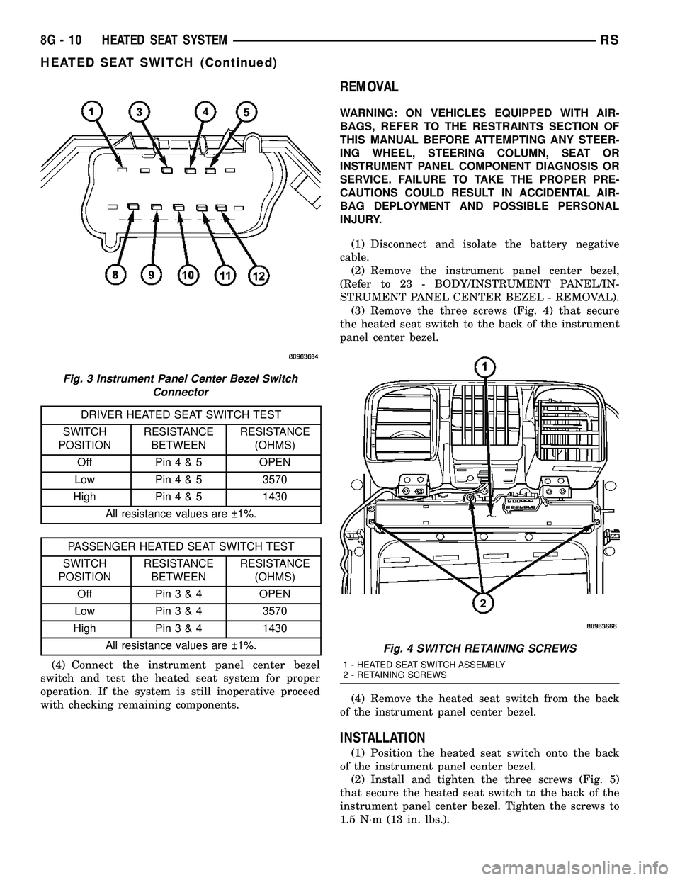
DRIVER HEATED SEAT SWITCH TEST
SWITCH
POSITIONRESISTANCE
BETWEENRESISTANCE
(OHMS)
Off Pin4&5OPEN
Low Pin4&53570
High Pin4&51430
All resistance values are 1%.
PASSENGER HEATED SEAT SWITCH TEST
SWITCH
POSITIONRESISTANCE
BETWEENRESISTANCE
(OHMS)
Off Pin3&4OPEN
Low Pin3&43570
High Pin3&41430
All resistance values are 1%.
(4) Connect the instrument panel center bezel
switch and test the heated seat system for proper
operation. If the system is still inoperative proceed
with checking remaining components.
REMOVAL
WARNING: ON VEHICLES EQUIPPED WITH AIR-
BAGS, REFER TO THE RESTRAINTS SECTION OF
THIS MANUAL BEFORE ATTEMPTING ANY STEER-
ING WHEEL, STEERING COLUMN, SEAT OR
INSTRUMENT PANEL COMPONENT DIAGNOSIS OR
SERVICE. FAILURE TO TAKE THE PROPER PRE-
CAUTIONS COULD RESULT IN ACCIDENTAL AIR-
BAG DEPLOYMENT AND POSSIBLE PERSONAL
INJURY.
(1) Disconnect and isolate the battery negative
cable.
(2) Remove the instrument panel center bezel,
(Refer to 23 - BODY/INSTRUMENT PANEL/IN-
STRUMENT PANEL CENTER BEZEL - REMOVAL).
(3) Remove the three screws (Fig. 4) that secure
the heated seat switch to the back of the instrument
panel center bezel.
(4) Remove the heated seat switch from the back
of the instrument panel center bezel.
INSTALLATION
(1) Position the heated seat switch onto the back
of the instrument panel center bezel.
(2) Install and tighten the three screws (Fig. 5)
that secure the heated seat switch to the back of the
instrument panel center bezel. Tighten the screws to
1.5 N´m (13 in. lbs.).
Fig. 3 Instrument Panel Center Bezel Switch
Connector
Fig. 4 SWITCH RETAINING SCREWS
1 - HEATED SEAT SWITCH ASSEMBLY
2 - RETAINING SCREWS
8G - 10 HEATED SEAT SYSTEMRS
HEATED SEAT SWITCH (Continued)
Page 360 of 2339
HORN
TABLE OF CONTENTS
page page
HORN SYSTEM
DESCRIPTION..........................1
OPERATION............................1
DIAGNOSIS AND TESTING
HORN SYSTEM........................1
HORN
DIAGNOSIS AND TESTING
HORN...............................3REMOVAL.............................4
INSTALLATION..........................4
HORN SWITCH
DESCRIPTION..........................4
HORN SYSTEM
DESCRIPTION
WARNING: ON VEHICLES EQUIPPED WITH AIR-
BAG, REFER TO ELECTRICAL, RESTRAINTS FOR
SAFETY PRECAUTIONS. DISCONNECT THE NEGA-
TIVE CABLE FROM THE BATTERY BEFORE SER-
VICING COMPONENTS INVOLVING THE AIRBAG
SYSTEM. ACCIDENTAL DEPLOYMENT OF AIRBAG
AND PERSONAL INJURY CAN RESULT.
The horn circuit consists of a horn switch, clock-
spring, horn relay, horns and Integrated Power Mod-
ule (IPM). The horn switch is a membrane switch
located in the airbag trim cover. The horns are
located forward of the left front wheel behind the
bumper fascia.
OPERATION
The horn relay plugs into the Integrated Power
Module (IPM) which is located in the engine com-
partment. For circuit information and component
locations, refer to the appropriate wiring information.
The wiring information includes wiring diagrams,
proper wire and connector repair procedures, details
of wire harness routing and retention, connector pin-
out information and location views for the various
wire harness connectors, splices and grounds.
The horns will not function if the switch is
ªCLOSEDº for more than 30 seconds. Once the
switch is ªOPENº, a 20±30 second delay will occur
before the horns are functional again.
DIAGNOSIS AND TESTING
HORN SYSTEM
WARNING: ON VEHICLES EQUIPPED WITH AIR-
BAGS, REFER TO ELECTRICAL, RESTRAINTS
BEFORE ATTEMPTING ANY STEERING WHEEL,
STEERING COLUMN, OR INSTRUMENT PANEL
COMPONENT DIAGNOSIS OR SERVICE. FAILURE
TO TAKE THE PROPER PRECAUTIONS COULD
RESULT IN ACCIDENTAL AIRBAG DEPLOYMENT
AND POSSIBLE PERSONAL INJURY.
Refer to Horn System Test below. If the horn does
not sound, check horn fuse located in the Integrated
Power Module (IPM). If the fuse is blown, replace
with the correct fuse. If the horns fail to sound and
the new fuse blows when depressing the horn switch,
a short circuit in the horn or the horn wiring
between the fuse terminal and the horn is responsi-
ble, or a defective horn switch allowed the horn to
burn out is responsible.
If the fuse is OK, test horn relay.
If the relay is OK, test horn.
CAUTION: Continuous sounding of horn may
cause horn failure.
Should the horn sound continuously, unplug the
horn relay from IPM.
Refer to the appropriate wiring information.
RSHORN8H-1
Page 363 of 2339
- DIAGNOSIS AND TESTING). If battery connec-
tions and battery charge is OK proceed to Step 2.
(2) Using a voltmeter, test for battery voltage at
both sides of horn fuse 7. If voltage is OK, on both
sides of fuse, proceed to Fuse OK. If voltage is OK,
on one side of fuse, the fuse is blown, proceed to Step
3.
(3) Using a suitable ammeter in place of the fuse,
test amperage draw of the horn circuit. If amperage
draw is greater than 20 amps without the horn
switch depressed, a grounded circuit exists between
the fuse and the horn relay. Proceed to Step 4. If
amperage draw is greater than 20 amps with the
horn switch depressed, a grounded circuit exists
between the horn relay and the horn. Proceed to step
Step 5.
(4) Remove the horn relay from the IPM. If the
amperage draw drops to 0 amps, the horn switch or
circuit is shorted. If the amperage draw does not
drop to 0 amps, repair short at the IPM.
(5) Disengage a wire connector from one of the
horns. If amperage drops and the connected horn
sounds, replace the faulty horn. If amperage does not
drop with both horns disconnected and the horn
switch depressed, proceed to Step 6.
(6) Using a continuity tester, with the horns dis-
connected test continuity of the X2 cavity of the horn
relay to ground. If continuity is detected, the circuit
is grounded between the Junction Block and the
horns. Locate and repair pinched harness.
FUSE OK
(1) Remove the horn relay from the intelligent
power module.
(2) Using a continuity tester, Depress horn switch
and test continuity from the X3 cavity of the horn
relay to ground.
(a) If continuity is detected, proceed to Step 3.
(b) If NO continuity, proceed to Step 4.
(3) Using a suitable jumper wire, jump across the
fuse F62 cavity and the X2 cavity of the horn relay in
the Junction Block.
(a) If the horn sounds, replace the horn relay.
(b) If the horn does not sound, proceed to Step 4.
(4) Remove airbag trim cover from steering wheel.
Refer to ELECTRICAL, RESTRAINTS.
(5) Test continuity across horn switch connectors
with horn switch depressed.
(a) If continuity is detected, repair open circuit
between the relay and the horn switch.
(b) If NO continuity, replace airbag trim cover.
(6) Install horn relay into intelligent power mod-
ule.
(7) Disengage wire connectors from horns.(8) Using a voltmeter, with the horn switch
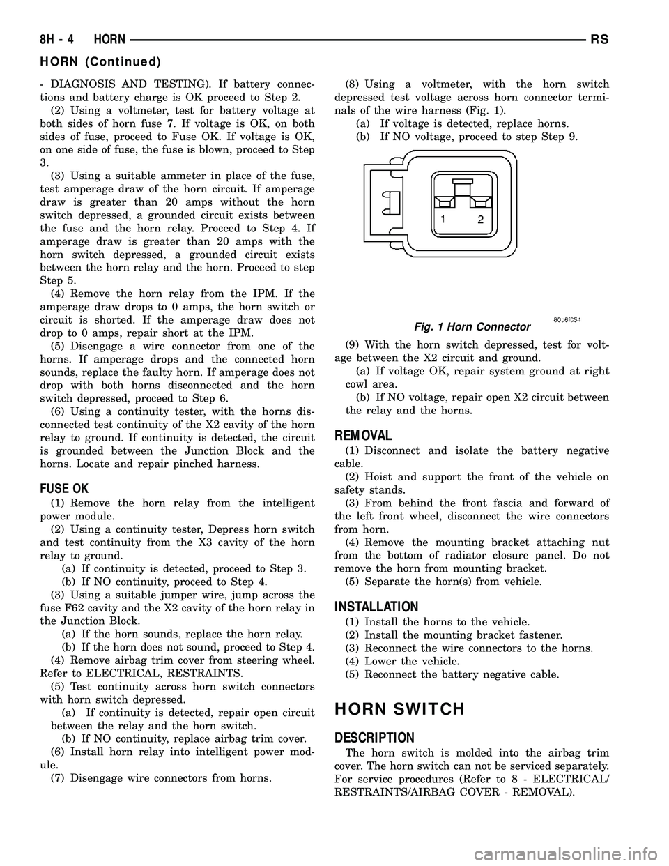
depressed test voltage across horn connector termi-
nals of the wire harness (Fig. 1).
(a) If voltage is detected, replace horns.
(b) If NO voltage, proceed to step Step 9.
(9) With the horn switch depressed, test for volt-
age between the X2 circuit and ground.
(a) If voltage OK, repair system ground at right
cowl area.
(b) If NO voltage, repair open X2 circuit between
the relay and the horns.
REMOVAL
(1) Disconnect and isolate the battery negative
cable.
(2) Hoist and support the front of the vehicle on
safety stands.
(3) From behind the front fascia and forward of
the left front wheel, disconnect the wire connectors
from horn.
(4) Remove the mounting bracket attaching nut
from the bottom of radiator closure panel. Do not
remove the horn from mounting bracket.
(5) Separate the horn(s) from vehicle.
INSTALLATION
(1) Install the horns to the vehicle.
(2) Install the mounting bracket fastener.
(3) Reconnect the wire connectors to the horns.
(4) Lower the vehicle.
(5) Reconnect the battery negative cable.
HORN SWITCH
DESCRIPTION
The horn switch is molded into the airbag trim
cover. The horn switch can not be serviced separately.
For service procedures (Refer to 8 - ELECTRICAL/
RESTRAINTS/AIRBAG COVER - REMOVAL).
Fig. 1 Horn Connector
8H - 4 HORNRS
HORN (Continued)
Page 372 of 2339
(4) Lower vehicle.
(5) Connect the negative cable.
SPARK PLUG
DESCRIPTION
DESCRIPTION - STANDARD 4 CYLINDER
All engines use resistor spark plugs. They have
resistance values ranging from 6,000 to 20,000 ohms
when checked with at least a 1000 volt spark plug
tester.
Do not use an ohm meter to check the resis-
tance of the spark plugs. This will give an inac-
curate reading.
Refer to the Specifications section for gap and type
of spark plug.
DESCRIPTION - PLATINUM PLUGS
The V6 engines use platinum resistor spark plugs.
They have resistance values of 6,000 to 20,000 ohms
when checked with at least a 1000 volt tester. For
spark plug identification and specifications, Refer to
the Specifications section.
Do not use an ohm meter to check the resis-
tance of the spark plugs. This will give an inac-
curate reading.When the spark plugs use a single or double plat-
inum tips and they have a recommended service life
of 100,000 miles for normal driving conditions per
schedule A in this manual. The spark plugs have a
recommended service life of 75,000 miles for severe
driving conditions per schedule B in this manual. A
thin platinum pad is welded to both or just the cen-
ter electrode end(s) as shown in (Fig. 13). Extreme
care must be used to prevent spark plug cross
threading, mis-gapping (Fig. 14) and ceramic insula-
tor damage during plug removal and installation.
CAUTION: Cleaning of the platinum plug may dam-
age the platinum tip.
Fig. 12 Knock Sensor
1 - GENERATOR
2 - INTAKE MANIFOLD
3 - KNOCK SENSOR
4-STARTER
Fig. 13 Platinum Pads
1 - APPLY ANTI-SEIZE COMPOUND HERE ONLY
2 - PLATINUM SPARK SURFACE
Fig. 14 Setting Spark Plug Electrode Gap
1 - TAPER GAUGE
RSIGNITION CONTROL8I-9
KNOCK SENSOR (Continued)
Page 374 of 2339
INSTRUMENT CLUSTER
TABLE OF CONTENTS
page page
INSTRUMENT CLUSTER
DESCRIPTION..........................1
OPERATION............................1
DIAGNOSIS AND TESTING
DIAGNOSIS AND TESTING - SELF-
DIAGNOSTICS.........................2
DIAGNOSIS AND TESTING - CLUSTER
DIAGNOSIS...........................3REMOVAL.............................11
INSTALLATION.........................11
CLUSTER LENS
REMOVAL.............................11
INSTALLATION.........................11
INSTRUMENT CLUSTER
DESCRIPTION
The instrumentation gauges are contained in a
subdial assembly within the instrument cluster. The
individual gauges are not serviceable. If one of the
cluster gauges becomes faulty, the entire cluster
would require replacement.
The Mechanical Instrument Cluster (MIC) with a
tachometer is equipped with a electronic vacuum flu-
orescent transmission range indicator (PRND3L),
odometer, and trip odometer display.
The MIC without a tachometer is equipped with a
Light Emitting Diode (LED) transmission range indi-
cator (PRND3L) and a vacuum fluorescent odometer
display.
The MIC is equipped with the following warning
lamps.
²Lift Gate Ajar
²Low Fuel Level
²Low Windshield Washer Fluid Level
²Cruise
²Battery Voltage
²Fasten Seat Belt
²Door Ajar
²Coolant Temperature
²Anti-Lock Brake
²Brake
²Oil Pressure
²MIL (Malfunction Indicator Lamp)
²VTSS/SKIS Indicator
²Airbag
²Traction Control
²Autostick
Export Only- uses a message center that displays
the following telltales:
²Turns Signals
²High Beam
²Tire Pressure Monitoring (TPM)²Glow Plug (Export Only)
²Supplemental Cabin Heater (Export Only)WATER IN FUEL LAMP - EXPORT
The Water In Fuel Lamp is located in the message
center. When moisture is found within the fuel sys-
tem, the sensor sends a message via the PCI data
bus to the instrument cluster. The MIC illuminates
the bulb in the message center, The sensor is located
underneath the vehicle, directly above the rear axle.
The sensor is housed within the fuel filter/water sep-
arator assembly cover. The sensor is not serviced sep-
arately. If found defective, the entire assembly cover
must be replaced.
OPERATION
Refer to the vehicle Owner's Manual for operation
instructions and conditions for the Instrument Clus-
ter Gauges.
WATER IN FUEL LAMP/SENSOR - EXPORT
The Water In Fuel Sensor is a resistive type
switch. It is calibrated to sense the different resis-
tance between diesel fuel and water. When water
enters the fuel system, it is caught in the bottom of
the fuel filter/water separator assembly, where the
sensor is located. Water has less resistance than die-
sel fuel. The sensor then sends a PCI data bus mes-
sage to the instrument cluster to illuminate the
lamp.
If the lamp is inoperative, perform the self diag-
nostic test on the instrument cluster to check the
lamp operation before continuing diagnosis.
RSINSTRUMENT CLUSTER8J-1
Page 380 of 2339
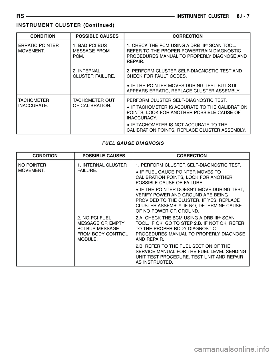
CONDITION POSSIBLE CAUSES CORRECTION
ERRATIC POINTER
MOVEMENT.1. BAD PCI BUS
MESSAGE FROM
PCM.1. CHECK THE PCM USING A DRB IIITSCAN TOOL.
REFER TO THE PROPER POWERTRAIN DIAGNOSTIC
PROCEDURES MANUAL TO PROPERLY DIAGNOSE AND
REPAIR.
2. INTERNAL
CLUSTER FAILURE.2. PERFORM CLUSTER SELF-DIAGNOSTIC TEST AND
CHECK FOR FAULT CODES.
²IF THE POINTER MOVES DURING TEST BUT STILL
APPEARS ERRATIC, REPLACE CLUSTER ASSEMBLY.
TACHOMETER
INACCURATE.TACHOMETER OUT
OF CALIBRATION.PERFORM CLUSTER SELF-DIAGNOSTIC TEST.
²IF TACHOMETER IS ACCURATE TO THE CALIBRATION
POINTS, LOOK FOR ANOTHER POSSIBLE CAUSE OF
INACCURACY.
²IF TACHOMETER IS NOT ACCURATE TO THE
CALIBRATION POINTS, REPLACE CLUSTER ASSEMBLY.
FUEL GAUGE DIAGNOSIS
CONDITION POSSIBLE CAUSES CORRECTION
NO POINTER
MOVEMENT.1. INTERNAL CLUSTER
FAILURE.1. PERFORM CLUSTER SELF-DIAGNOSTIC TEST.
²IF FUEL GAUGE POINTER MOVES TO
CALIBRATION POINTS, LOOK FOR ANOTHER
POSSIBLE CAUSE OF FAILURE.
²IF THE POINTER DOESN'T MOVE DURING TEST,
VERIFY POWER AND GROUND ARE BEING
PROVIDED TO THE CLUSTER. IF YES, REPLACE
CLUSTER ASSEMBLY. IF NO, DETERMINE CAUSE
OF NO POWER OR GROUND.
2. NO PCI FUEL
MESSAGE OR EMPTY
PCI BUS MESSAGE
FROM BODY CONTROL
MODULE.2.A. CHECK THE BCM USING A DRB IIITSCAN
TOOL. IF OK, GO TO STEP 2.B. IF NOT OK, REFER
TO THE PROPER BODY DIAGNOSTIC
PROCEDURES MANUAL TO PROPERLY DIAGNOSE
AND REPAIR.
2.B. REFER TO THE FUEL SECTION OF THE
SERVICE MANUAL FOR THE FUEL LEVEL SENDING
UNIT TEST PROCEDURE. TEST UNIT AND REPAIR
AS INSTRUCTED.
RSINSTRUMENT CLUSTER8J-7
INSTRUMENT CLUSTER (Continued)
Page 381 of 2339
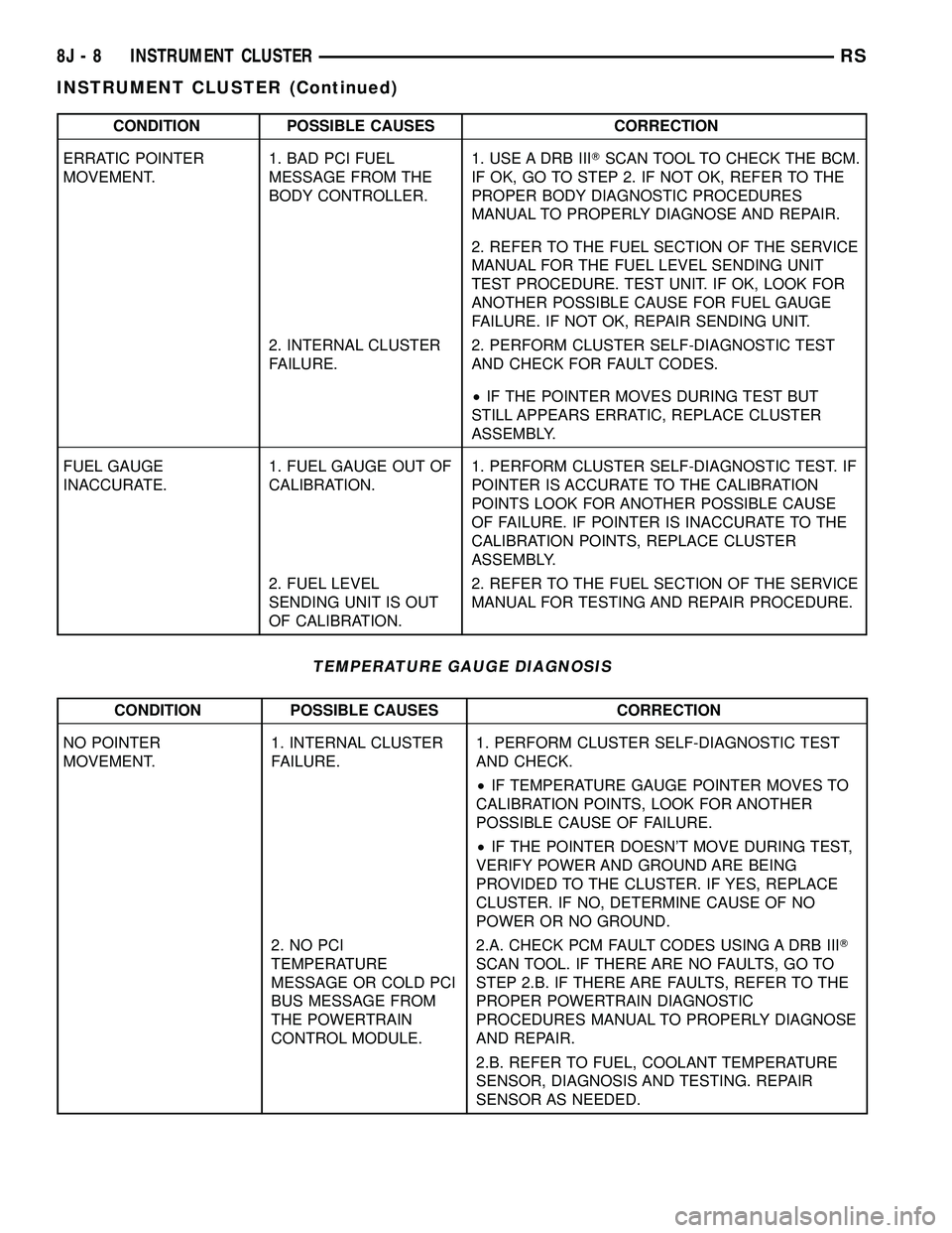
CONDITION POSSIBLE CAUSES CORRECTION
ERRATIC POINTER
MOVEMENT.1. BAD PCI FUEL
MESSAGE FROM THE
BODY CONTROLLER.1. USE A DRB IIITSCAN TOOL TO CHECK THE BCM.
IF OK, GO TO STEP 2. IF NOT OK, REFER TO THE
PROPER BODY DIAGNOSTIC PROCEDURES
MANUAL TO PROPERLY DIAGNOSE AND REPAIR.
2. REFER TO THE FUEL SECTION OF THE SERVICE
MANUAL FOR THE FUEL LEVEL SENDING UNIT
TEST PROCEDURE. TEST UNIT. IF OK, LOOK FOR
ANOTHER POSSIBLE CAUSE FOR FUEL GAUGE
FAILURE. IF NOT OK, REPAIR SENDING UNIT.
2. INTERNAL CLUSTER
FAILURE.2. PERFORM CLUSTER SELF-DIAGNOSTIC TEST
AND CHECK FOR FAULT CODES.
²IF THE POINTER MOVES DURING TEST BUT
STILL APPEARS ERRATIC, REPLACE CLUSTER
ASSEMBLY.
FUEL GAUGE
INACCURATE.1. FUEL GAUGE OUT OF
CALIBRATION.1. PERFORM CLUSTER SELF-DIAGNOSTIC TEST. IF
POINTER IS ACCURATE TO THE CALIBRATION
POINTS LOOK FOR ANOTHER POSSIBLE CAUSE
OF FAILURE. IF POINTER IS INACCURATE TO THE
CALIBRATION POINTS, REPLACE CLUSTER
ASSEMBLY.
2. FUEL LEVEL
SENDING UNIT IS OUT
OF CALIBRATION.2. REFER TO THE FUEL SECTION OF THE SERVICE
MANUAL FOR TESTING AND REPAIR PROCEDURE.
TEMPERATURE GAUGE DIAGNOSIS
CONDITION POSSIBLE CAUSES CORRECTION
NO POINTER
MOVEMENT.1. INTERNAL CLUSTER
FAILURE.1. PERFORM CLUSTER SELF-DIAGNOSTIC TEST
AND CHECK.
²IF TEMPERATURE GAUGE POINTER MOVES TO
CALIBRATION POINTS, LOOK FOR ANOTHER
POSSIBLE CAUSE OF FAILURE.
²IF THE POINTER DOESN'T MOVE DURING TEST,
VERIFY POWER AND GROUND ARE BEING
PROVIDED TO THE CLUSTER. IF YES, REPLACE
CLUSTER. IF NO, DETERMINE CAUSE OF NO
POWER OR NO GROUND.
2. NO PCI
TEMPERATURE
MESSAGE OR COLD PCI
BUS MESSAGE FROM
THE POWERTRAIN
CONTROL MODULE.2.A. CHECK PCM FAULT CODES USING A DRB IIIT
SCAN TOOL. IF THERE ARE NO FAULTS, GO TO
STEP 2.B. IF THERE ARE FAULTS, REFER TO THE
PROPER POWERTRAIN DIAGNOSTIC
PROCEDURES MANUAL TO PROPERLY DIAGNOSE
AND REPAIR.
2.B. REFER TO FUEL, COOLANT TEMPERATURE
SENSOR, DIAGNOSIS AND TESTING. REPAIR
SENSOR AS NEEDED.
8J - 8 INSTRUMENT CLUSTERRS
INSTRUMENT CLUSTER (Continued)