Locking CHRYSLER VOYAGER 2005 Owner's Manual
[x] Cancel search | Manufacturer: CHRYSLER, Model Year: 2005, Model line: VOYAGER, Model: CHRYSLER VOYAGER 2005Pages: 2339, PDF Size: 59.69 MB
Page 199 of 2339
DESCRIPTION - ELECTRONIC VARIABLE
BRAKE PROPORTIONING
Vehicles equipped with ABS use electronic variable
brake proportioning (EVBP) to balance front-to-rear
braking. The EVBP is used in place of a rear propor-
tioning valve. The EVBP system uses the ABS system
to control the slip of the rear wheels in partial brak-
ing range. The braking force of the rear wheels is con-
trolled electronically by using the inlet and outlet
valves located in the integrated control unit (ICU).
EVBP activation is invisible to the customer since
there is no pump motor noise or brake pedal feedback.
DESCRIPTION - TRACTION CONTROL SYSTEM
Traction control reduces wheel slip and maintains
traction at the driving wheels at speeds below 56
km/h (35 mph) when road surfaces are slippery. The
traction control system reduces wheel slip by braking
the wheel that is losing traction.
HYDRAULIC SHUTTLE VALVES
Two pressure relief hydraulic shuttle valves are
included on vehicles with traction control. These
valves are located inside the HCU and cannot be ser-
viced separately from the HCU.
TRACTION CONTROL LAMP
The traction control function lamp is located in the
transmission range indicator display of the instru-
ment cluster, displaying TRAC, TRAC OFF or nei-
ther depending on system mode.
The TRAC OFF lamp is controlled by a Traction
Control Off switch that is a momentary contact type
switch. The Traction Control Off switch is located on
the steering column upper shroud.
OPERATION
OPERATION - ANTILOCK BRAKE SYSTEM
There are a few performance characteristics of the
Mark 20e Antilock Brake System that may at first
seem abnormal, but in fact are normal. These char-
acteristics are described below.
NORMAL BRAKING
Under normal braking conditions, the ABS func-
tions the same as a standard base brake system with
a diagonally split master cylinder and conventional
vacuum assist.
ABS BRAKING
ABS operation is available at all vehicle speeds above
3±5 mph. If a wheel locking tendency is detected during
a brake application, the brake system enters the ABS
mode. During ABS braking, hydraulic pressure in thefour wheel circuits is modulated to prevent any wheel
from locking. Each wheel circuit is designed with a set of
electric solenoids to allow modulation, although for vehi-
cle stability, both rear wheel solenoids receive the same
electrical signal. Wheel lockup may be perceived at the
very end of an ABS stop and is considered normal.
During an ABS stop, the brakes hydraulic system
is still diagonally split. However, the brake system
pressure is further split into three control channels.
During antilock operation of the vehicle's brake sys-
tem, the front wheels are controlled independently
and are on two separate control channels, and the
rear wheels of the vehicle are controlled together.
The system can build and release pressure at each
wheel, depending on signals generated by the wheel
speed sensors (WSS) at each wheel and received at
the controller antilock brake (CAB).
NOISE AND BRAKE PEDAL FEEL
During ABS braking, some brake pedal movement
may be felt. In addition, ABS braking will create
ticking, popping, or groaning noises heard by the
driver. This is normal and is due to pressurized fluid
being transferred between the master cylinder and
the brakes. If ABS operation occurs during hard
braking, some pulsation may be felt in the vehicle
body due to fore and aft movement of the suspension
as brake pressures are modulated.
At the end of an ABS stop, ABS is turned off when
the vehicle is slowed to a speed of 3±4 mph. There may
be a slight brake pedal drop anytime that the ABS is
deactivated, such as at the end of the stop when the
vehicle speed is less than 3 mph or during an ABS stop
where ABS is no longer required. These conditions exist
when a vehicle is being stopped on a road surface with
patches of ice, loose gravel, or sand on it. Also, stopping
a vehicle on a bumpy road surface activates ABS
because of the wheel hop caused by the bumps.
TIRE NOISE AND MARKS
Although the ABS system prevents complete wheel
lockup, some wheel slip is desired in order to achieve
optimum braking performance. Wheel slip is defined
as follows: 0 percent slip means the wheel is rolling
freely and 100 percent slip means the wheel is fully
locked. During brake pressure modulation, wheel slip
is allowed to reach up to 25±30 percent. This means
that the wheel rolling velocity is 25±30 percent less
than that of a free rolling wheel at a given vehicle
speed. This slip may result in some tire chirping,
depending on the road surface. This sound should not
be interpreted as total wheel lockup.
Complete wheel lockup normally leaves black tire
marks on dry pavement. The ABS will not leave dark
black tire marks since the wheel never reaches a
fully locked condition. However, tire marks may be
noticeable as light patched marks.
5 - 88 BRAKES - ABSRS
BRAKES - ABS (Continued)
Page 228 of 2339
REMOVAL
GENERATOR AND AIR CONDITIONING BELT
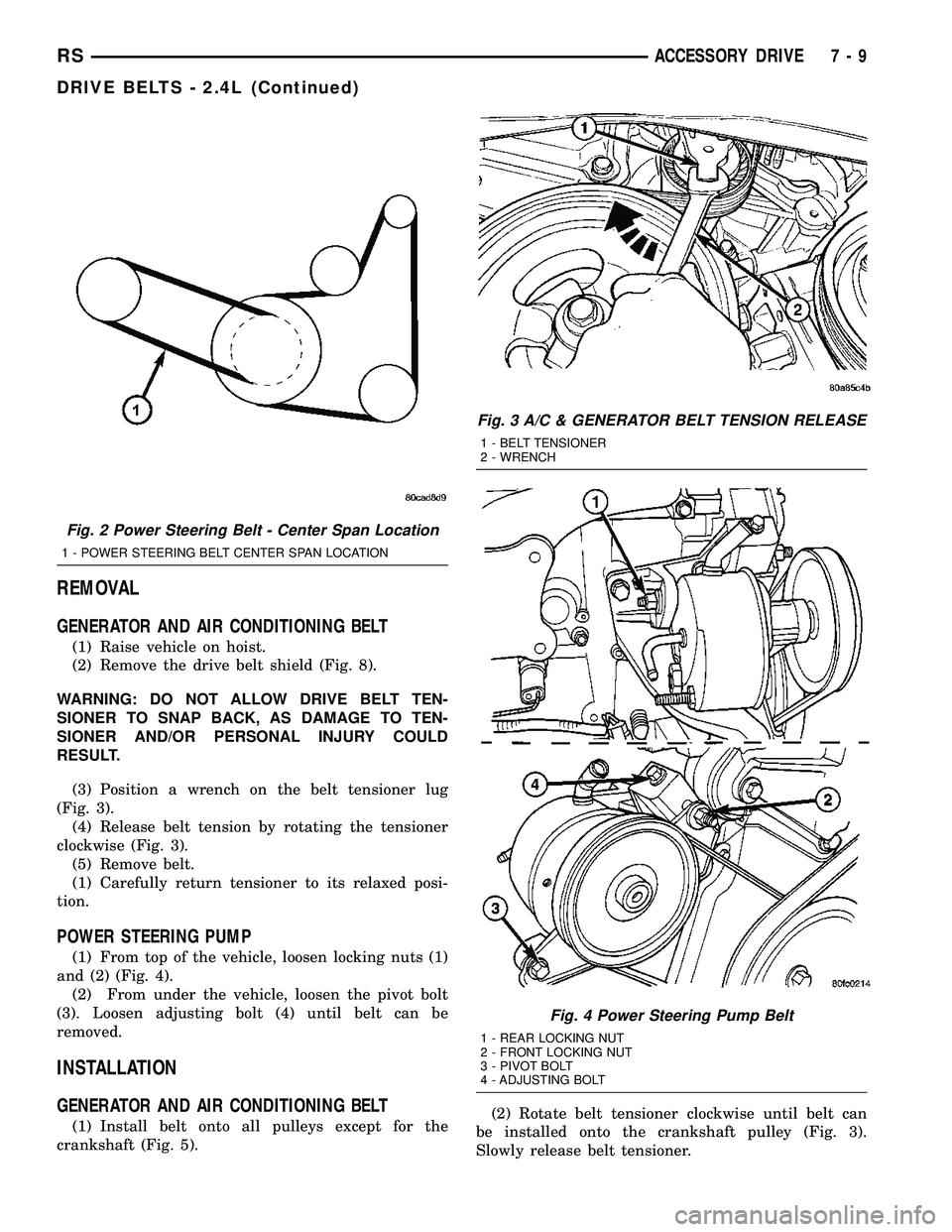
(1) Raise vehicle on hoist.
(2) Remove the drive belt shield (Fig. 8).
WARNING: DO NOT ALLOW DRIVE BELT TEN-
SIONER TO SNAP BACK, AS DAMAGE TO TEN-
SIONER AND/OR PERSONAL INJURY COULD
RESULT.
(3) Position a wrench on the belt tensioner lug
(Fig. 3).
(4) Release belt tension by rotating the tensioner
clockwise (Fig. 3).
(5) Remove belt.
(1) Carefully return tensioner to its relaxed posi-
tion.
POWER STEERING PUMP
(1) From top of the vehicle, loosen locking nuts (1)
and (2) (Fig. 4).
(2) From under the vehicle, loosen the pivot bolt
(3). Loosen adjusting bolt (4) until belt can be
removed.
INSTALLATION
GENERATOR AND AIR CONDITIONING BELT
(1) Install belt onto all pulleys except for the
crankshaft (Fig. 5).(2) Rotate belt tensioner clockwise until belt can
be installed onto the crankshaft pulley (Fig. 3).
Slowly release belt tensioner.
Fig. 2 Power Steering Belt - Center Span Location
1 - POWER STEERING BELT CENTER SPAN LOCATION
Fig. 3 A/C & GENERATOR BELT TENSION RELEASE
1 - BELT TENSIONER
2 - WRENCH
Fig. 4 Power Steering Pump Belt
1 - REAR LOCKING NUT
2 - FRONT LOCKING NUT
3 - PIVOT BOLT
4 - ADJUSTING BOLT
RSACCESSORY DRIVE7-9
DRIVE BELTS - 2.4L (Continued)
Page 229 of 2339
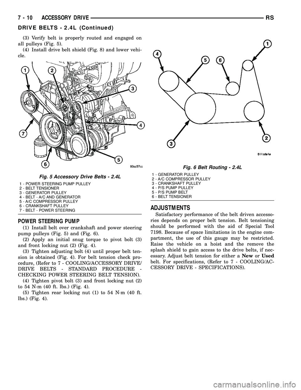
(3) Verify belt is properly routed and engaged on
all pulleys (Fig. 5).
(4) Install drive belt shield (Fig. 8) and lower vehi-
cle.
POWER STEERING PUMP
(1) Install belt over crankshaft and power steering
pump pulleys (Fig. 5) and (Fig. 6).
(2) Apply an initial snug torque to pivot bolt (3)
and front locking nut (2) (Fig. 4).
(3) Tighten adjusting bolt (4) until proper belt ten-
sion is obtained (Fig. 4). For belt tension check pro-
cedure, (Refer to 7 - COOLING/ACCESSORY DRIVE/
DRIVE BELTS - STANDARD PROCEDURE -
CHECKING POWER STEERING BELT TENSION).
(4) Tighten pivot bolt (3) and front locking nut (2)
to 54 N´m (40 ft. lbs.) (Fig. 4).
(5) Tighten rear locking nut (1) to 54 N´m (40 ft.
lbs.) (Fig. 4).
ADJUSTMENTS
Satisfactory performance of the belt driven accesso-
ries depends on proper belt tension. Belt tensioning
should be performed with the aid of Special Tool
7198. Because of space limitations in the engine com-
partment, the use of this gauge may be restricted.
Raise the vehicle on a hoist and the remove the
splash shield to gain access to the drive belts, if nec-
essary. Adjust belt tension for either aNeworUsed
belt. For specifications, (Refer to 7 - COOLING/AC-
CESSORY DRIVE - SPECIFICATIONS).
Fig. 5 Accessory Drive Belts - 2.4L
1 - POWER STEERING PUMP PULLEY
2 - BELT TENSIONER
3 - GENERATOR PULLEY
4 - BELT - A/C AND GENERATOR
5 - A/C COMPRESSOR PULLEY
6 - CRANKSHAFT PULLEY
7 - BELT - POWER STEERING
Fig. 6 Belt Routing - 2.4L
1 - GENERATOR PULLEY
2 - A/C COMPRESSOR PULLEY
3 - CRANKSHAFT PULLEY
4 - P/S PUMP PULLEY
5 - P/S PUMP BELT
6 - BELT TENSIONER
7 - 10 ACCESSORY DRIVERS
DRIVE BELTS - 2.4L (Continued)
Page 271 of 2339
(3) Install screws holding CD changer.
(4) Reconnect the battery negative cable.
DVD PLAYER
DESCRIPTION
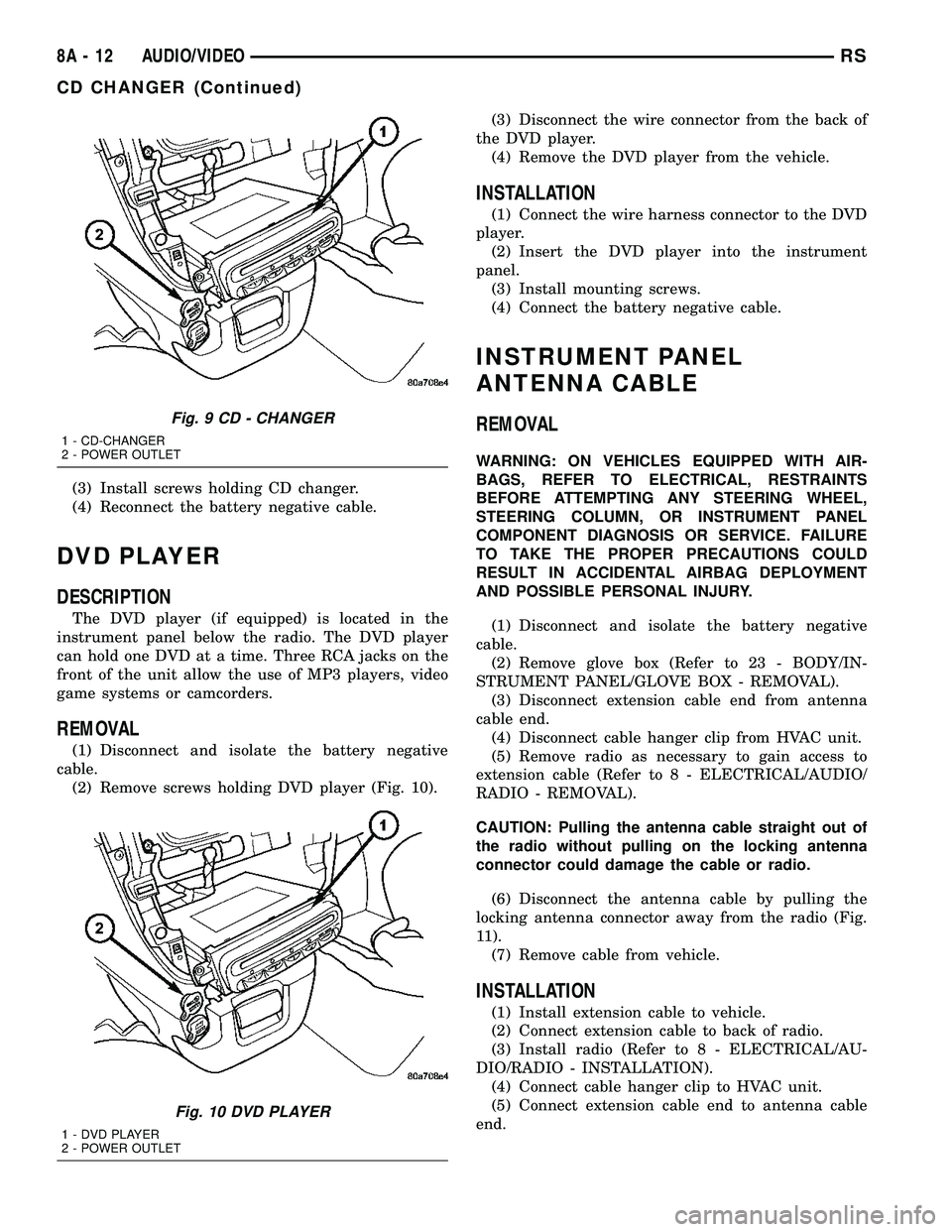
The DVD player (if equipped) is located in the
instrument panel below the radio. The DVD player
can hold one DVD at a time. Three RCA jacks on the
front of the unit allow the use of MP3 players, video
game systems or camcorders.
REMOVAL
(1) Disconnect and isolate the battery negative
cable.
(2) Remove screws holding DVD player (Fig. 10).(3) Disconnect the wire connector from the back of
the DVD player.
(4) Remove the DVD player from the vehicle.
INSTALLATION
(1) Connect the wire harness connector to the DVD
player.
(2) Insert the DVD player into the instrument
panel.
(3) Install mounting screws.
(4) Connect the battery negative cable.
INSTRUMENT PANEL
ANTENNA CABLE
REMOVAL
WARNING: ON VEHICLES EQUIPPED WITH AIR-
BAGS, REFER TO ELECTRICAL, RESTRAINTS
BEFORE ATTEMPTING ANY STEERING WHEEL,
STEERING COLUMN, OR INSTRUMENT PANEL
COMPONENT DIAGNOSIS OR SERVICE. FAILURE
TO TAKE THE PROPER PRECAUTIONS COULD
RESULT IN ACCIDENTAL AIRBAG DEPLOYMENT
AND POSSIBLE PERSONAL INJURY.
(1) Disconnect and isolate the battery negative
cable.
(2) Remove glove box (Refer to 23 - BODY/IN-
STRUMENT PANEL/GLOVE BOX - REMOVAL).
(3) Disconnect extension cable end from antenna
cable end.
(4) Disconnect cable hanger clip from HVAC unit.
(5) Remove radio as necessary to gain access to
extension cable (Refer to 8 - ELECTRICAL/AUDIO/
RADIO - REMOVAL).
CAUTION: Pulling the antenna cable straight out of
the radio without pulling on the locking antenna
connector could damage the cable or radio.
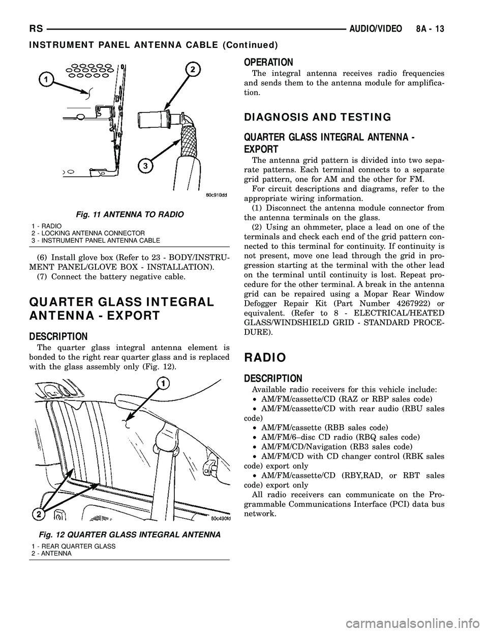
(6) Disconnect the antenna cable by pulling the
locking antenna connector away from the radio (Fig.
11).
(7) Remove cable from vehicle.
INSTALLATION
(1) Install extension cable to vehicle.
(2) Connect extension cable to back of radio.
(3) Install radio (Refer to 8 - ELECTRICAL/AU-
DIO/RADIO - INSTALLATION).
(4) Connect cable hanger clip to HVAC unit.
(5) Connect extension cable end to antenna cable
end.
Fig. 9 CD - CHANGER
1 - CD-CHANGER
2 - POWER OUTLET
Fig. 10 DVD PLAYER
1 - DVD PLAYER
2 - POWER OUTLET
8A - 12 AUDIO/VIDEORS
CD CHANGER (Continued)
Page 272 of 2339
(6) Install glove box (Refer to 23 - BODY/INSTRU-
MENT PANEL/GLOVE BOX - INSTALLATION).
(7) Connect the battery negative cable.
QUARTER GLASS INTEGRAL
ANTENNA - EXPORT
DESCRIPTION
The quarter glass integral antenna element is
bonded to the right rear quarter glass and is replaced
with the glass assembly only (Fig. 12).
OPERATION
The integral antenna receives radio frequencies
and sends them to the antenna module for amplifica-
tion.
DIAGNOSIS AND TESTING
QUARTER GLASS INTEGRAL ANTENNA -
EXPORT
The antenna grid pattern is divided into two sepa-
rate patterns. Each terminal connects to a separate
grid pattern, one for AM and the other for FM.
For circuit descriptions and diagrams, refer to the
appropriate wiring information.
(1) Disconnect the antenna module connector from
the antenna terminals on the glass.
(2) Using an ohmmeter, place a lead on one of the
terminals and check each end of the grid pattern con-
nected to this terminal for continuity. If continuity is
not present, move one lead through the grid in pro-
gression starting at the terminal with the other lead
on the terminal until continuity is lost. Repeat pro-
cedure for the other terminal. A break in the antenna
grid can be repaired using a Mopar Rear Window
Defogger Repair Kit (Part Number 4267922) or
equivalent. (Refer to 8 - ELECTRICAL/HEATED
GLASS/WINDSHIELD GRID - STANDARD PROCE-
DURE).
RADIO
DESCRIPTION
Available radio receivers for this vehicle include:
²AM/FM/cassette/CD (RAZ or RBP sales code)
²AM/FM/cassette/CD with rear audio (RBU sales
code)
²AM/FM/cassette (RBB sales code)
²AM/FM/6±disc CD radio (RBQ sales code)
²AM/FM/CD/Navigation (RB3 sales code)
²AM/FM/CD with CD changer control (RBK sales
code) export only
²AM/FM/cassette/CD (RBY,RAD, or RBT sales
code) export only
All radio receivers can communicate on the Pro-
grammable Communications Interface (PCI) data bus
network.
Fig. 11 ANTENNA TO RADIO
1 - RADIO
2 - LOCKING ANTENNA CONNECTOR
3 - INSTRUMENT PANEL ANTENNA CABLE
Fig. 12 QUARTER GLASS INTEGRAL ANTENNA
1 - REAR QUARTER GLASS
2 - ANTENNA
RSAUDIO/VIDEO8A-13
INSTRUMENT PANEL ANTENNA CABLE (Continued)
Page 274 of 2339
CAUTION: Pulling the antenna cable straight out of
the radio without pulling on the locking antenna
connector could damage the cable or radio.
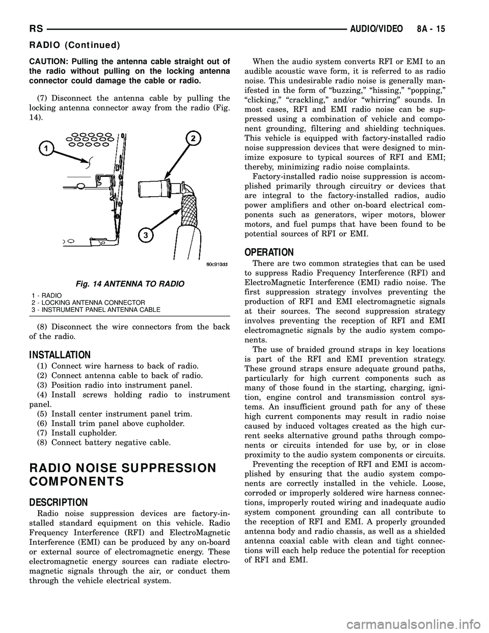
(7) Disconnect the antenna cable by pulling the
locking antenna connector away from the radio (Fig.
14).
(8) Disconnect the wire connectors from the back
of the radio.
INSTALLATION
(1) Connect wire harness to back of radio.
(2) Connect antenna cable to back of radio.
(3) Position radio into instrument panel.
(4) Install screws holding radio to instrument
panel.
(5) Install center instrument panel trim.
(6) Install trim panel above cupholder.
(7) Install cupholder.
(8) Connect battery negative cable.
RADIO NOISE SUPPRESSION
COMPONENTS
DESCRIPTION
Radio noise suppression devices are factory-in-
stalled standard equipment on this vehicle. Radio
Frequency Interference (RFI) and ElectroMagnetic
Interference (EMI) can be produced by any on-board
or external source of electromagnetic energy. These
electromagnetic energy sources can radiate electro-
magnetic signals through the air, or conduct them
through the vehicle electrical system.When the audio system converts RFI or EMI to an
audible acoustic wave form, it is referred to as radio
noise. This undesirable radio noise is generally man-
ifested in the form of ªbuzzing,º ªhissing,º ªpopping,º
ªclicking,º ªcrackling,º and/or ªwhirringº sounds. In
most cases, RFI and EMI radio noise can be sup-
pressed using a combination of vehicle and compo-
nent grounding, filtering and shielding techniques.
This vehicle is equipped with factory-installed radio
noise suppression devices that were designed to min-
imize exposure to typical sources of RFI and EMI;
thereby, minimizing radio noise complaints.
Factory-installed radio noise suppression is accom-
plished primarily through circuitry or devices that
are integral to the factory-installed radios, audio
power amplifiers and other on-board electrical com-
ponents such as generators, wiper motors, blower
motors, and fuel pumps that have been found to be
potential sources of RFI or EMI.
OPERATION
There are two common strategies that can be used
to suppress Radio Frequency Interference (RFI) and
ElectroMagnetic Interference (EMI) radio noise. The
first suppression strategy involves preventing the
production of RFI and EMI electromagnetic signals
at their sources. The second suppression strategy
involves preventing the reception of RFI and EMI
electromagnetic signals by the audio system compo-
nents.
The use of braided ground straps in key locations
is part of the RFI and EMI prevention strategy.
These ground straps ensure adequate ground paths,
particularly for high current components such as
many of those found in the starting, charging, igni-
tion, engine control and transmission control sys-
tems. An insufficient ground path for any of these
high current components may result in radio noise
caused by induced voltages created as the high cur-
rent seeks alternative ground paths through compo-
nents or circuits intended for use by, or in close
proximity to the audio system components or circuits.
Preventing the reception of RFI and EMI is accom-
plished by ensuring that the audio system compo-
nents are correctly installed in the vehicle. Loose,
corroded or improperly soldered wire harness connec-
tions, improperly routed wiring and inadequate audio
system component grounding can all contribute to
the reception of RFI and EMI. A properly grounded
antenna body and radio chassis, as well as a shielded
antenna coaxial cable with clean and tight connec-
tions will each help reduce the potential for reception
of RFI and EMI.
Fig. 14 ANTENNA TO RADIO
1 - RADIO
2 - LOCKING ANTENNA CONNECTOR
3 - INSTRUMENT PANEL ANTENNA CABLE
RSAUDIO/VIDEO8A-15
RADIO (Continued)
Page 290 of 2339
trical connector on the vehicle wiring harness. The
power source for the CAB is through the ignition
switch in the RUN or ON position. The CAB is on
the PCI bus.
OPERATION
The primary functions of the controller antilock
brake (CAB) are to:
²Monitor the antilock brake system for proper
operation.
²Detect wheel locking or wheel slipping tenden-
cies by monitoring the speed of all four wheels of the
vehicle.
²Control fluid modulation to the wheel brakes
while the system is in an ABS mode.
²Store diagnostic information.
²Provide communication to the DRBIIItscan tool
while in diagnostic mode.
²Illuminate the amber ABS warning indicator
lamp.
²(With traction control only) Illuminate the TRAC
ON lamp in the message center on the instrument
panel when a traction control event occurs.
²(with traction control only) Illuminate the TRAC
OFF lamp when the amber ABS warning indicator
lamp illuminates.
The CAB constantly monitors the antilock brake
system for proper operation. If the CAB detects a
fault, it will turn on the amber ABS warning indica-
tor lamp and disable the antilock braking system.
The normal base braking system will remain opera-
tional.
NOTE: If the vehicle is equipped with traction con-
trol, the TRAC OFF lamp will illuminate anytime the
amber ABS warning indicator lamp illuminates.The CAB continuously monitors the speed of each
wheel through the signals generated by the wheel
speed sensors to determine if any wheel is beginning
to lock. When a wheel locking tendency is detected,
the CAB commands the CAB command coils to actu-
ate. The coils then open and close the valves in the
HCU that modulate brake fluid pressure in some or
all of the hydraulic circuits. The CAB continues to
control pressure in individual hydraulic circuits until
a locking tendency is no longer present.
The CAB contains a self-diagnostic program that
monitors the antilock brake system for system faults.
When a fault is detected, the amber ABS warning
indicator lamp is turned on and the fault diagnostic
trouble code (DTC) is then stored in a diagnostic pro-
gram memory. A latched fault will disable certain
system functionality for the current ignition cycle. An
unlatched fault will disable certain system function-
ality until the fault condition disappears. These
DTC's will remain in the CAB memory even after the
ignition has been turned off. The DTC's can be read
and cleared from the CAB memory by a technician
using the DRBIIItscan tool. If not cleared with a
DRBIIItscan tool, the fault occurrence and DTC will
be automatically cleared from the CAB memory after
the identical fault has not been seen during the next
3,500 miles. Drive-off may be required for the amber
ABS warning indicator lamp to go out on the next
ignition cycle.
CAB INPUTS
²Wheel speed sensors (four)
²Brake lamp switch
²Ignition switch
²System and pump voltage
²Ground
²Traction control switch (if equipped)
²Diagnostic communication (PCI)
CAB OUTPUTS
²Amber ABS warning indicator lamp actuation
(via BUS)
²Red BRAKE warning indicator lamp actuation
(via BUS)
²Instrument cluster (MIC) communication (PCI)
²Traction control lamps (if equipped)
²Diagnostic communication (PCI, via BUS)
REMOVAL
(1) Disconnect the battery cables.
(2) Remove the battery (Refer to 8 - ELECTRI-
CAL/BATTERY SYSTEM/BATTERY - REMOVAL).
(3) Disconnect the vacuum hose connector at the
tank built into the battery tray.
(4) Remove the screw securing the coolant filler
neck to the battery tray.
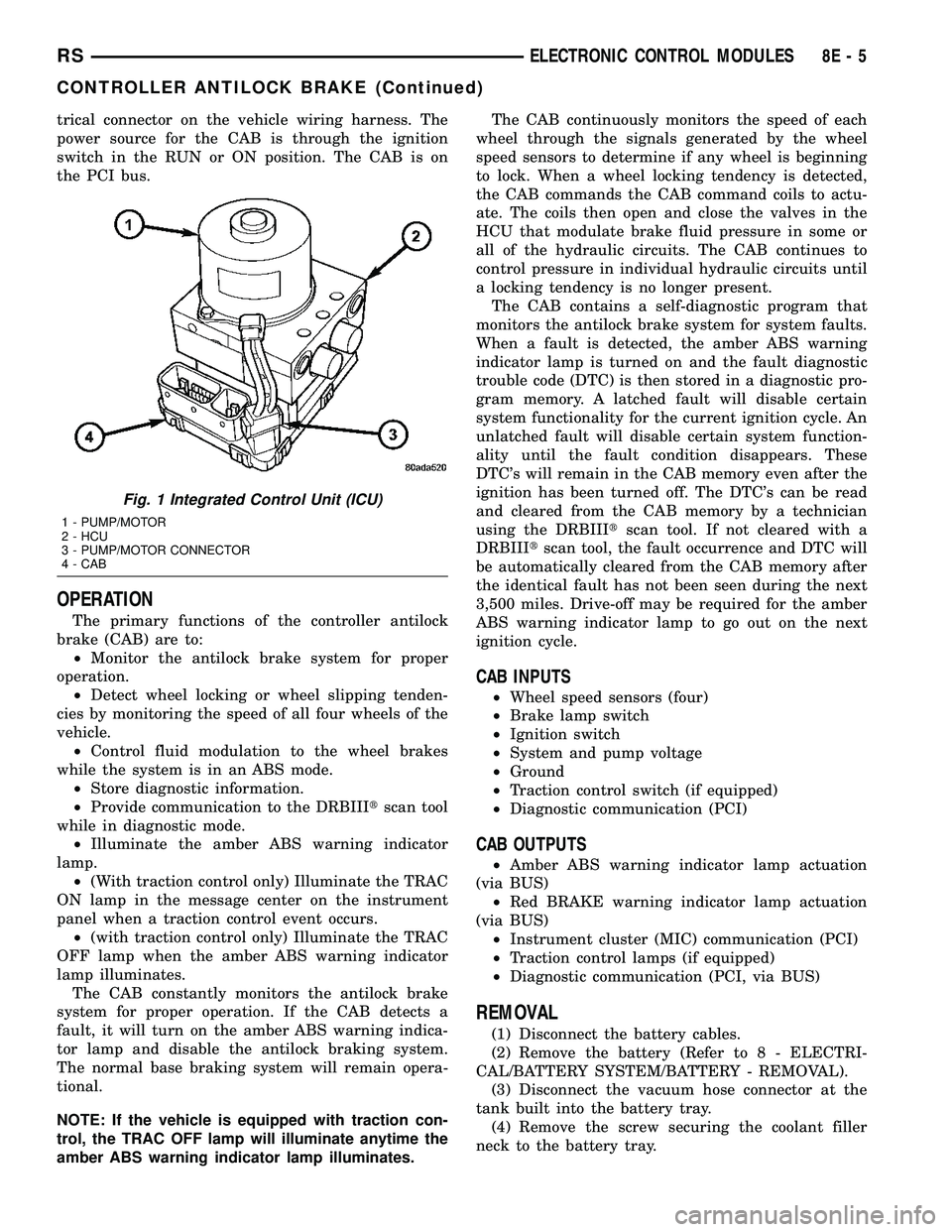
Fig. 1 Integrated Control Unit (ICU)
1 - PUMP/MOTOR
2 - HCU
3 - PUMP/MOTOR CONNECTOR
4 - CAB
RSELECTRONIC CONTROL MODULES8E-5
CONTROLLER ANTILOCK BRAKE (Continued)
Page 304 of 2339
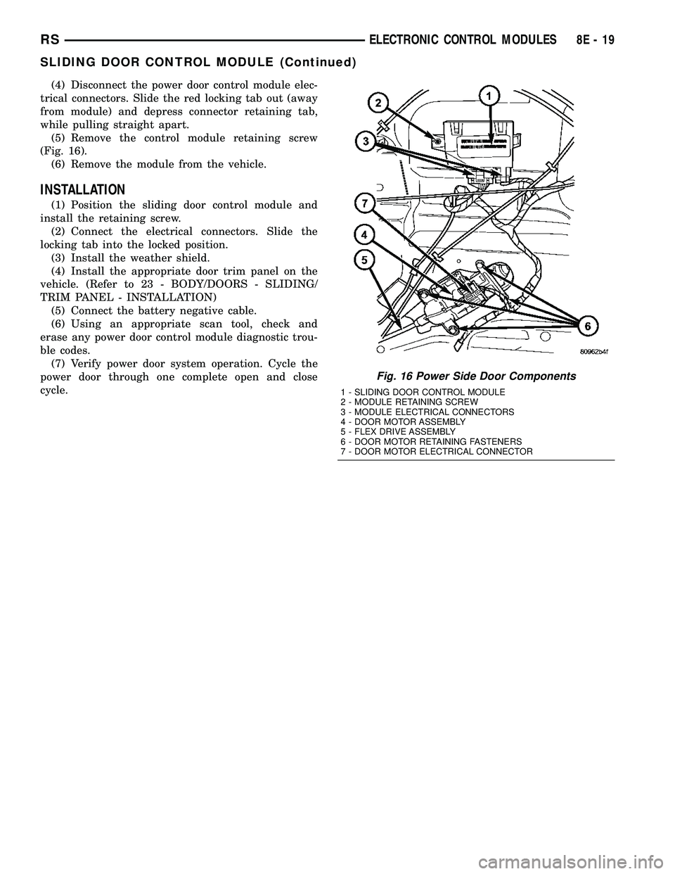
(4) Disconnect the power door control module elec-
trical connectors. Slide the red locking tab out (away
from module) and depress connector retaining tab,
while pulling straight apart.
(5) Remove the control module retaining screw
(Fig. 16).
(6) Remove the module from the vehicle.
INSTALLATION
(1) Position the sliding door control module and
install the retaining screw.
(2) Connect the electrical connectors. Slide the
locking tab into the locked position.
(3) Install the weather shield.
(4) Install the appropriate door trim panel on the
vehicle. (Refer to 23 - BODY/DOORS - SLIDING/
TRIM PANEL - INSTALLATION)
(5) Connect the battery negative cable.
(6) Using an appropriate scan tool, check and
erase any power door control module diagnostic trou-
ble codes.
(7) Verify power door system operation. Cycle the
power door through one complete open and close
cycle.
Fig. 16 Power Side Door Components
1 - SLIDING DOOR CONTROL MODULE
2 - MODULE RETAINING SCREW
3 - MODULE ELECTRICAL CONNECTORS
4 - DOOR MOTOR ASSEMBLY
5 - FLEX DRIVE ASSEMBLY
6 - DOOR MOTOR RETAINING FASTENERS
7 - DOOR MOTOR ELECTRICAL CONNECTOR
RSELECTRONIC CONTROL MODULES8E-19
SLIDING DOOR CONTROL MODULE (Continued)
Page 390 of 2339

(3) Gently push the plunger on the brake lamp
switch in until it stops.
(4) With the switch in this depressed position
(plunger pushed in), use an ohmmeter to test each of
the three internal switches as shown (Fig. 2). You
should achieve the results as listed in the figure.
If you do not achieve the results as listed in both
figures, the switch is faulty and must be replaced.
Refer to Removal And Installation in this section.
If the switch is found to be operating properly, it
may be misadjusted. Do not reinstall the switch,
replace it. (Refer to 8 - ELECTRICAL/LAMPS/
LIGHTING - EXTERIOR/BRAKE LAMP SWITCH -
INSTALLATION)
CAUTION: The switch can only be adjusted once.
That is during initial installation of the switch. If the
switch is not adjusted properly or has beenremoved for any reason, a new switch must be
installed and adjusted.
REMOVAL
(1) Disconnect and isolate the battery negative
cable from its post on the battery.
(2) Remove silencer panel below steering column
and knee blocker.
(3) Remove the brake lamp switch by rotating the
switch in a counterclockwise direction approximately
30 degrees and pulling it out of the bracket (Fig. 3).
(4) Release the locking tab and disconnect the wir-
ing connector from the switch.
(5) Discard the brake lamp switch. It must not be
reused.
INSTALLATION
CAUTION: Do not reuse the original brake lamp
switch. The switch can only be adjusted once. That
is during initial installation of the switch. If the
switch is not adjusted properly or has been
removed for some service, a new switch must be
installed and adjusted.
(1) Mount and adjust the NEW brake lamp switch
using the following procedure:
(a) Connect the wiring connector to the switch
and latch the locking tab.
Fig. 1 SWITCH TEST - RELEASED POSITION
Fig. 2 SWITCH TEST - DEPRESSED POSITION
Fig. 3 Brake Lamp Switch And Pedal With Bracket
1 - BRAKE LAMP SWITCH
2 - WIRING CONNECTOR
3 - PEDAL AND BRACKET
RSLAMPS/LIGHTING - EXTERIOR8L-5
BRAKE LAMP SWITCH (Continued)
Page 443 of 2339
POWER LOCKS
TABLE OF CONTENTS
page page
POWER LOCKS
DESCRIPTION.........................20
OPERATION...........................21
DOOR CYLINDER LOCK SWITCH - EXPORT
DESCRIPTION.........................22
OPERATION...........................22
DIAGNOSIS AND TESTING
DOOR CYLINDER LOCK SWITCH -
EXPORT............................22
REMOVAL.............................22
INSTALLATION.........................22
DOOR LOCK MOTOR
DIAGNOSIS AND TESTING
DOOR LOCK MOTOR..................23
DOOR LOCK SWITCH
DIAGNOSIS AND TESTING
DOOR LOCK SWITCH..................23
REMOVAL.............................23INSTALLATION.........................23
KEYLESS ENTRY TRANSMITTER
DIAGNOSIS AND TESTING
KEYLESS ENTRY TRANSMITTER.........24
STANDARD PROCEDURE
STANDARD PROCEDURE - HORN CHIRP
PREFERENCE........................24
STANDARD PROCEDURE - BATTERY
REPLACEMENT.......................24
STANDARD PROCEDURE - REMOTE
KEYLESS ENTRY TRANSMITTER
PROGRAMMING......................24
SPECIFICATIONS
SPECIFICATIONS - TRANSMITTER RANGE . 24
SPECIFICATIONS - BATTERY............24
SLIDING DOOR LOCK MOTOR
REMOVAL.............................25
INSTALLATION.........................25
POWER LOCKS
DESCRIPTION
POWER LOCKS
The power lock system allows all of the doors to be
locked or unlocked electrically by operating a switch
on either front door trim panel. The power lock sys-
tem receives non-switched battery current through a
fuse in the Integrated Power Module (IPM), so that
the power locks remain operational, regardless of the
ignition switch position.
The Body Control Module (BCM) locks the doors
automatically when the vehicle is driven beyond the
speed of 25.7 Km/h (15 mph), all doors are closed, the
accelerator pedal is depressed and the door lock actu-
ation had not been previously activated. The rolling
door lock feature is customer programmable.
This vehicle also offers several customer program-
mable features, which allows the selection of several
optional electronic features to suit individual prefer-
ences.
The power lock system for this vehicle can also be
operated remotely using the available Remote Key-
less Entry (RKE) system radio frequency transmit-
ters, if equipped.
AUTOMATIC DOOR LOCKS
When enabled, this feature will lock all of the door
locks if all of the doors are closed and the vehicle
speed goes above 25.7 km/h (15 mph). If a door
unlock has occurred, then the BCM will perform
another auto lock, if the doors did not electrically
unlock, another auto lock will not occur.
DOOR LOCK INHIBIT
When the key is in the ignition (in any switch posi-
tion) and either front door is opened, the door lock
switches LOCK functions are disabled. The
UN-LOCK functions are still functional. This protects
against locking the vehicle with the key still in the
ignition. The RKE key fob will still lock the doors.
After the key is removed from the ignition or the
doors are closed, the power door locks will operate
normally.
REMOTE KEYLESS ENTRY
The Remote Keyless Entry (RKE) system allows
the use of a remote battery-powered radio transmit-
ter to communicate with the BCM to actuate the
power lock system.
The RKE transmitters are also equipped with a
Panic button. If the Panic button on the RKE trans-
mitter is depressed, the horn will sound and the
exterior lights will flash on the vehicle for about
three minutes, or until the Panic button is depressed
8N - 20 POWER LOCKSRS