coil CHRYSLER VOYAGER 2005 Owner's Manual
[x] Cancel search | Manufacturer: CHRYSLER, Model Year: 2005, Model line: VOYAGER, Model: CHRYSLER VOYAGER 2005Pages: 2339, PDF Size: 59.69 MB
Page 366 of 2339

FIRING ORDERAUTO SHUT DOWN RELAY
DESCRIPTION
The relay is located in the Power Distribution Cen-
ter (PDC). For the location of the relay within the
PDC, refer to the PDC cover for location. Check elec-
trical terminals for corrosion and repair as necessary
OPERATION
The engine switched battery (NGC vehicles)
informs the PCM when the ASD relay energizes. A 12
volt signal at this input indicates to the PCM that
the ASD has been activated. This input is also used
to power certain drivers on NGC vehicles.
When energized, the ASD relay on NGC vehicles
provides power to operate the injectors, ignition coil,
generator field, O2 sensor heaters (both upstream
and downstream), evaporative purge solenoid, EGR
solenoid (if equipped) wastegate solenoid (if
equipped), and NVLD solenoid (if equipped).
The ASD relay also provides a sense circuit to the
PCM for diagnostic purposes. If the PCM does not
receive 12 volts from this input after grounding the
control side of the ASD relay, it sets a Diagnostic
Trouble Code (DTC). The PCM energizes the ASD
any time there is an engine speed that exceeds a pre-
determined value (typically about 50 rpm). The ASD
relay can also be energized after the engine has been
turned off to perform an O2 sensor heater test, if
vehicle is equipped with OBD II diagnostics.
As mentioned earlier, the PCM energizes the ASD
relay during an O2 sensor heater test. On NGC vehi-
cles it checks the O2 heater upon vehicle start. The
PCM still operates internally to perform several
checks, including monitoring the O2 sensor heaters.
FIRING ORDER 2.4L
Firing Order 1-2-3-4-5-6 3.3/3.8L
1 - Electrical Connector
RSIGNITION CONTROL8I-3
IGNITION CONTROL (Continued)
Page 369 of 2339
(6) Pull sensor up out of the chain case cover.Do
not pull on the sensor wiring.There is an O-ring
on the body of the sensor. The O-ring may make
removal difficult. A light tap to top of sensor prior to
removal may reduce force needed for removal.
INSTALLATION
INSTALLATION - 2.4L
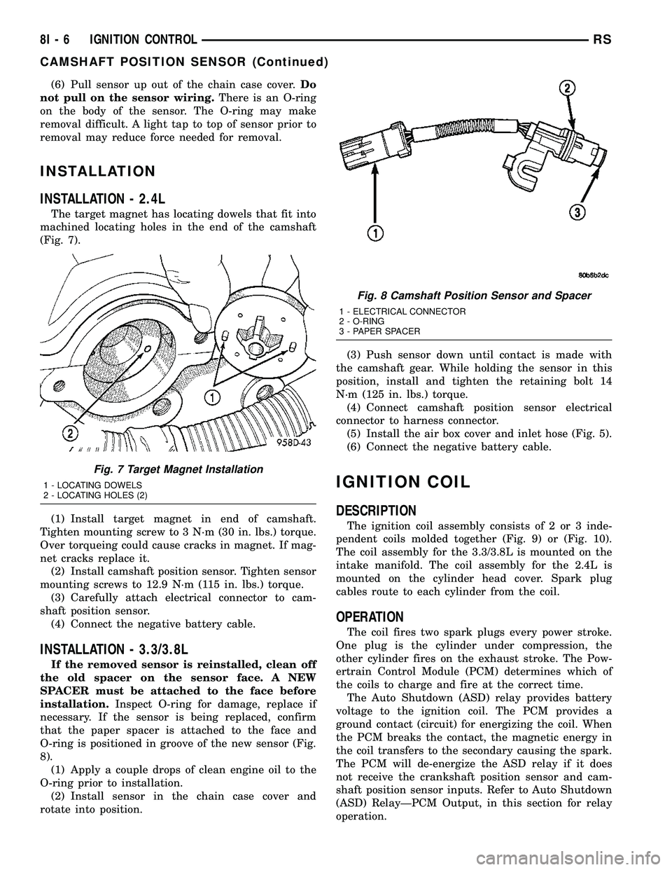
The target magnet has locating dowels that fit into
machined locating holes in the end of the camshaft
(Fig. 7).
(1) Install target magnet in end of camshaft.
Tighten mounting screw to 3 N´m (30 in. lbs.) torque.
Over torqueing could cause cracks in magnet. If mag-
net cracks replace it.
(2) Install camshaft position sensor. Tighten sensor
mounting screws to 12.9 N´m (115 in. lbs.) torque.
(3) Carefully attach electrical connector to cam-
shaft position sensor.
(4) Connect the negative battery cable.
INSTALLATION - 3.3/3.8L
If the removed sensor is reinstalled, clean off
the old spacer on the sensor face. A NEW
SPACER must be attached to the face before
installation.Inspect O-ring for damage, replace if
necessary. If the sensor is being replaced, confirm
that the paper spacer is attached to the face and
O-ring is positioned in groove of the new sensor (Fig.
8).
(1) Apply a couple drops of clean engine oil to the
O-ring prior to installation.
(2) Install sensor in the chain case cover and
rotate into position.(3) Push sensor down until contact is made with
the camshaft gear. While holding the sensor in this
position, install and tighten the retaining bolt 14
N´m (125 in. lbs.) torque.
(4) Connect camshaft position sensor electrical
connector to harness connector.
(5) Install the air box cover and inlet hose (Fig. 5).
(6) Connect the negative battery cable.
IGNITION COIL
DESCRIPTION
The ignition coil assembly consists of 2 or 3 inde-
pendent coils molded together (Fig. 9) or (Fig. 10).
The coil assembly for the 3.3/3.8L is mounted on the
intake manifold. The coil assembly for the 2.4L is
mounted on the cylinder head cover. Spark plug
cables route to each cylinder from the coil.
OPERATION
The coil fires two spark plugs every power stroke.
One plug is the cylinder under compression, the
other cylinder fires on the exhaust stroke. The Pow-
ertrain Control Module (PCM) determines which of
the coils to charge and fire at the correct time.
The Auto Shutdown (ASD) relay provides battery
voltage to the ignition coil. The PCM provides a
ground contact (circuit) for energizing the coil. When
the PCM breaks the contact, the magnetic energy in
the coil transfers to the secondary causing the spark.
The PCM will de-energize the ASD relay if it does
not receive the crankshaft position sensor and cam-
shaft position sensor inputs. Refer to Auto Shutdown
(ASD) RelayÐPCM Output, in this section for relay
operation.
Fig. 7 Target Magnet Installation
1 - LOCATING DOWELS
2 - LOCATING HOLES (2)
Fig. 8 Camshaft Position Sensor and Spacer
1 - ELECTRICAL CONNECTOR
2 - O-RING
3 - PAPER SPACER
8I - 6 IGNITION CONTROLRS
CAMSHAFT POSITION SENSOR (Continued)
Page 370 of 2339

REMOVAL
REMOVAL - 2.4L
The electronic ignition coil pack attaches directly
to the valve cover.
(1) Diconnect the negative battery cable.
(2) Disconnect electrical connector from coil pack.
(3) Remove coil pack mounting bolts.(4) Remove coil pack and heat shield (Fig. 9).
REMOVAL - 3.3/3.8L
(1) Disconnect the negative battery cable.
(2) Remove the throttle and speed control cables
from clip.
(3) Remove 2 bolts from the Power steering reser-
voir to intake manifold.
(4) Loosen the lower nut for the power steering
reservoir from stud on ignition coil bracket.
(5) Reposition the Power steering reservoir (Fig.
11).
(6) Remove the ignition cables from the ignition
coil.
(7) Disconnect the electrical connector from the
ignition coil.
(8) Remove 2 nuts from the ignition coil studs.
INSTALLATION
INSTALLATION - 2.4L
(1) Install ignition coil and heat shield to valve
cover and tighten bolts.
(2) Connect the electrical connector to the ignition
coil.
(3) Transfer spark plug cables to new coil pack.
The coil pack towers are numbered with the cylinder
identification. Be sure the ignition cables are fully
seated onto the towers.
(4) Connect the negative battery cable.
Fig. 9 IGNITION COIL - 2.4L
Fig. 10 IGNITION COIL - 3.3/3.8L
1 -Ignition Coil
Fig. 11 IGNITION COIL BRACKET 3.3/3.8L
RSIGNITION CONTROL8I-7
IGNITION COIL (Continued)
Page 371 of 2339
INSTALLATION - 3.3/3.8L
(1) Install coil over studs on bracket.
(2) Install 2 nuts to the ignition coil studs. Tighten
nuts and bolts.
(3) Connect the electrical connector to the ignition
coil.
(4) Install the ignition cables to the ignition coil.
(5) Reposition the Power steering reservoir. Slide
bracket over the mounting stud (Fig. 11).
(6) Install 2 bolts to the Power steering reservoir
to intake manifold.
(7) Tighten the lower nut to stud on ignition coil
bracket.
(8) Install the throttle and speed control cables to
clip.
(9) Connect the negative battery cable.
KNOCK SENSOR
DESCRIPTION
The knock sensor threads into the cylinder block.
The knock sensor is designed to detect engine vibra-
tion that is caused by detonation.
OPERATION
When the knock sensor detects a knock in one of
the cylinders, it sends an input signal to the PCM. In
response, the PCM retards ignition timing for all cyl-
inders by a scheduled amount.
Knock sensors contain a piezoelectric material
which constantly vibrates and sends an input voltage
(signal) to the PCM while the engine operates. As the
intensity of the crystal's vibration increases, the
knock sensor output voltage also increases.
The voltage signal produced by the knock sensor
increases with the amplitude of vibration. The PCM
receives as an input the knock sensor voltage signal.
If the signal rises above a predetermined level, the
PCM will store that value in memory and retard
ignition timing to reduce engine knock. If the knock
sensor voltage exceeds a preset value, the PCM
retards ignition timing for all cylinders. It is not a
selective cylinder retard.
The PCM ignores knock sensor input during engine
idle conditions. Once the engine speed exceeds a
specified value, knock retard is allowed.
Knock retard uses its own short term and long
term memory program.
Long term memory stores previous detonation
information in its battery-backed RAM. The maxi-
mum authority that long term memory has over tim-
ing retard can be calibrated.
Short term memory is allowed to retard timing up
to a preset amount under all operating conditions (as
long as rpm is above the minimum rpm) except WOT.The PCM, using short term memory, can respond
quickly to retard timing when engine knock is
detected. Short term memory is lost any time the
ignition key is turned off.
NOTE: Over or under tightening affects knock sen-
sor performance, possibly causing improper spark
control.
REMOVAL
REMOVAL - 2.4L
The knock sensor threads into the side of the cyl-
inder block in front of the starter (Fig. 12).
(1) Disconnect electrical connector from knock sen-
sor.
(2) Use a crow foot socket to remove the knock
sensors.
REMOVAL - 3.8L
The knock sensor threads into the side of the cyl-
inder block in the rear.
(1) Disconnect the negative battery cable.
(2) Raise vehicle and support.
(3) On All Wheel Drive vehicles remove the PTU
(Power Transfer Unit), refer to the Transmission sec-
tion for more information.
(4) Disconnect electrical connector from knock sen-
sor.
(5) Use a crow foot socket to remove the knock
sensor.
INSTALLATION
INSTALLATION - 2.4L
The knock sensor threads into the side of the cyl-
inder block in front of the starter (Fig. 12).
(1) Install knock sensor. Tighten knock sensor to
10 N´m (7 ft. lbs.) torque.Over or under tighten-
ing effects knock sensor performance, possibly
causing improper spark control.
(2) Attach electrical connector to knock sensor.
INSTALLATION - 3.8L
The knock sensor threads into the side of the cyl-
inder block in the rear.
(1) Install knock sensor. Tighten knock sensor to
10 N´m (7 ft. lbs.) torque.Over or under tighten-
ing effects knock sensor performance, possibly
causing improper spark control.
(2) Attach electrical connector to knock sensor.
(3) On All Wheel Drive vehicles install the PTU
(Power Transfer Unit) for the rear wheels, refer to
the Transmission section for more information.
8I - 8 IGNITION CONTROLRS
IGNITION COIL (Continued)
Page 373 of 2339
REMOVAL
When replacing the spark plugs and spark plug
cables, route the cables correctly and secure them in
the appropriate retainers. Failure to route the cables
properly can cause the radio to reproduce ignition
noise, cross ignition of the spark plugs orshort cir-
cuit the cables to ground.
Always remove cables by grasping at the boot,
rotating the boot 1/2 turn, and pulling straight back
in a steady motion.
(1) Prior to removing the spark plug, spray com-
pressed air around the spark plug hole and the area
around the spark plug.
(2) Remove the spark plug using a quality socket
with a foam insert.
(3) Inspect the spark plug condition.
INSTALLATION
When replacing the spark plugs and spark plug
cables, route the cables correctly and secure them in
the appropriate retainers. Failure to route the cables
properly can cause the radio to reproduce ignition
noise, cross ignition of the spark plugs orshort cir-
cuit the cables to ground.
(1) Coat threads of spark plug with anti-seize. Be
sure not to get anti-seizeANYWHERE BUT ON
THE THREADS OF THE SPARK PLUG as
shown in (Fig. 13).
(2) To avoid cross threading, start the spark plug
into the cylinder head by hand.
(3) Tighten spark plugs to 17.5 N´m (13 ft. lbs.)
torque.
(4) Install spark plug cables over spark plugs. A
click will be heard and felt when the cable properly
attaches to the spark plug.
SPARK PLUG CABLE
DESCRIPTION
Spark Plug cables are sometimes referred to as
secondary ignition wires. The wires transfer electri-
cal current from the ignition coil pack to individualspark plugs at each cylinder. The resistive spark plug
cables are of nonmetallic construction. The cables
provide suppression of radio frequency emissions
from the ignition system.
Check the spark plug cable connections for good
contact at the coil, and spark plugs. Terminals should
be fully seated. The insulators should be in good con-
dition and should fit tightly on the coil, and spark
plugs. Spark plug cables with insulators that are
cracked or torn must be replaced.
Clean Spark Plug cables with a cloth moistened
with a non-flammable solvent. Wipe the cables dry.
Check for brittle or cracked insulation. The spark
plug cables and spark plug boots are made from high
temperature materials.
REMOVAL - 2.0/2.4L
Failure to route the cables properly could cause the
radio to reproduce ignition noise, cross ignition of the
spark plugs or short circuit the cables to ground.
Remove spark plug cable from coil first.
Always remove the spark plug cable by grasping
the top of the spark plug insulator, turning the boot
1/2 turn and pulling straight up in a steady motion.
INSTALLATION - 2.0/2.4L
Failure to route the cables properly could cause the
radio to reproduce ignition noise, cross ignition of the
spark plugs or short circuit the cables to ground.
Install spark plug insulators over spark plugs.
Ensure the top of the spark plug insulator covers the
upper end of the spark plug tube, then connect the
other end to coil pack.
8I - 10 IGNITION CONTROLRS
SPARK PLUG (Continued)
Page 498 of 2339
Service replacement clocksprings are shipped pre-
centered and with a molded plastic shield that snaps
onto the rotor over the release button. The release
button secures the centered clockspring rotor to the
clockspring case and the shield prevents the release
button from being inadvertently depressed during
shipment and handling, but the shield must be
removed from the clockspring after it is installed on
the steering column (Refer to 8 - ELECTRICAL/RE-
STRAINTS/CLOCKSPRING - STANDARD PROCE-
DURE).
The clockspring cannot be repaired. If the clock-
spring is faulty, damaged, or if the driver airbag has
been deployed, the clockspring must be replaced.
OPERATION
The clockspring is a mechanical electrical circuit
component that is used to provide continuous electri-
cal continuity between the fixed instrument panel
wire harness and the electrical components mounted
on or in the rotating steering wheel. The rotating
electrical components include the driver airbag, the
horn switch, the speed control switches, and the
remote radio switches, if the vehicle is so equipped.
The clockspring case is positioned and secured to the
upper steering column housing near the top of the
steering column. The connector receptacles on the
tail of the clockspring case connect the clockspring to
the vehicle electrical system through two connectors
from the instrument panel wire harness.
The clockspring rotor is movable and is keyed by
the tower formation that is molded onto the upper
surface of the rotor hub to an opening that is cast
into the steering wheel armature. Rubber bumper
blocks on either side of the clockspring tower forma-
tion eliminate contact noise between the clockspring
tower and the steering wheel. The lobe of the turn
signal cancel cam on the lower surface of the clock-
spring rotor hub contacts a turn signal cancel actua-
tor of the multi-function switch to provide automatic
turn signal cancellation. The yellow or black-sleeved
pigtail wires on the upper surface of the clockspring
rotor connect the clockspring to the driver airbag,
while a steering wheel wire harness connects the
connector receptacle on the upper surface of the
clockspring rotor to the horn switch and, if the vehi-
cle is so equipped, to the optional speed control
switches and remote radio switches on the steering
wheel.
The clockspring tape has travel limits and can be
damaged by being wound too tightly during full stop-
to-stop steering wheel rotation. To prevent this from
occurring, the clockspring is centered when it is
installed on the steering column. Centering the clock-
spring indexes the clockspring tape to the movable
steering components so that the tape can operatewithin its designed travel limits. However, if the
clockspring is removed from the steering column or if
the steering shaft is disconnected from the steering
gear, the clockspring spool can change position rela-
tive to the movable steering components and must be
re-centered following completion of the service or the
tape may be damaged (Refer to 8 - ELECTRICAL/
RESTRAINTS/CLOCKSPRING - STANDARD PRO-
CEDURE).
Service replacement clocksprings are shipped pre-
centered and with a plastic shield installed over the
clockspring release button. This shield should not be
removed and the release button should not be
depressed until the clockspring has been installed on
the steering column. If the release button is
depressed before the clockspring is installed on a
steering column, the clockspring centering procedure
must be performed (Refer to 8 - ELECTRICAL/RE-
STRAINTS/CLOCKSPRING - STANDARD PROCE-
DURE).
STANDARD PROCEDURE - CLOCKSPRING
CENTERING
If the rotating tape (wire coil) in the clockspring is
not positioned properly with the steering wheel and
the front wheels, the clockspring may fail. The fol-
lowing procedure MUST BE USED to center the
clockspring if it is not known to be properly posi-
tioned, or if the front wheels were moved from the
straight ahead position.
(1) Position steering wheel and front wheels
straight ahead.
(2) Release hood latch and open hood.
(3) Disconnect and isolate the battery negative
cable.
(4) Wait two minutes for the system reserve capac-
itor to discharge before beginning any airbag compo-
nent service.
(5) Remove driver airbag from steering wheel
(Refer to 8 - ELECTRICAL/RESTRAINTS/DRIVER
AIRBAG - REMOVAL).
(6) Disconnect wire connectors from back of driver
airbag.
(7) Disconnect the 2±way connector from remote
radio control harness (if equipped).
(8) Disconnect the 4±way harness connector from
the speed control (if equipped)/horn harness to the
clockspring.
(9) Remove steering wheel (Refer to 19 - STEER-
ING/COLUMN/STEERING WHEEL - REMOVAL).
(10) Rotate the clockspring rotor clockwise until
the rotor stops. Do not apply excessive force.
(11) From the end of travel, rotate the rotor two
turns counterclockwise until the wires end up at the
top.
RSRESTRAINTS8O-11
CLOCKSPRING (Continued)
Page 583 of 2339
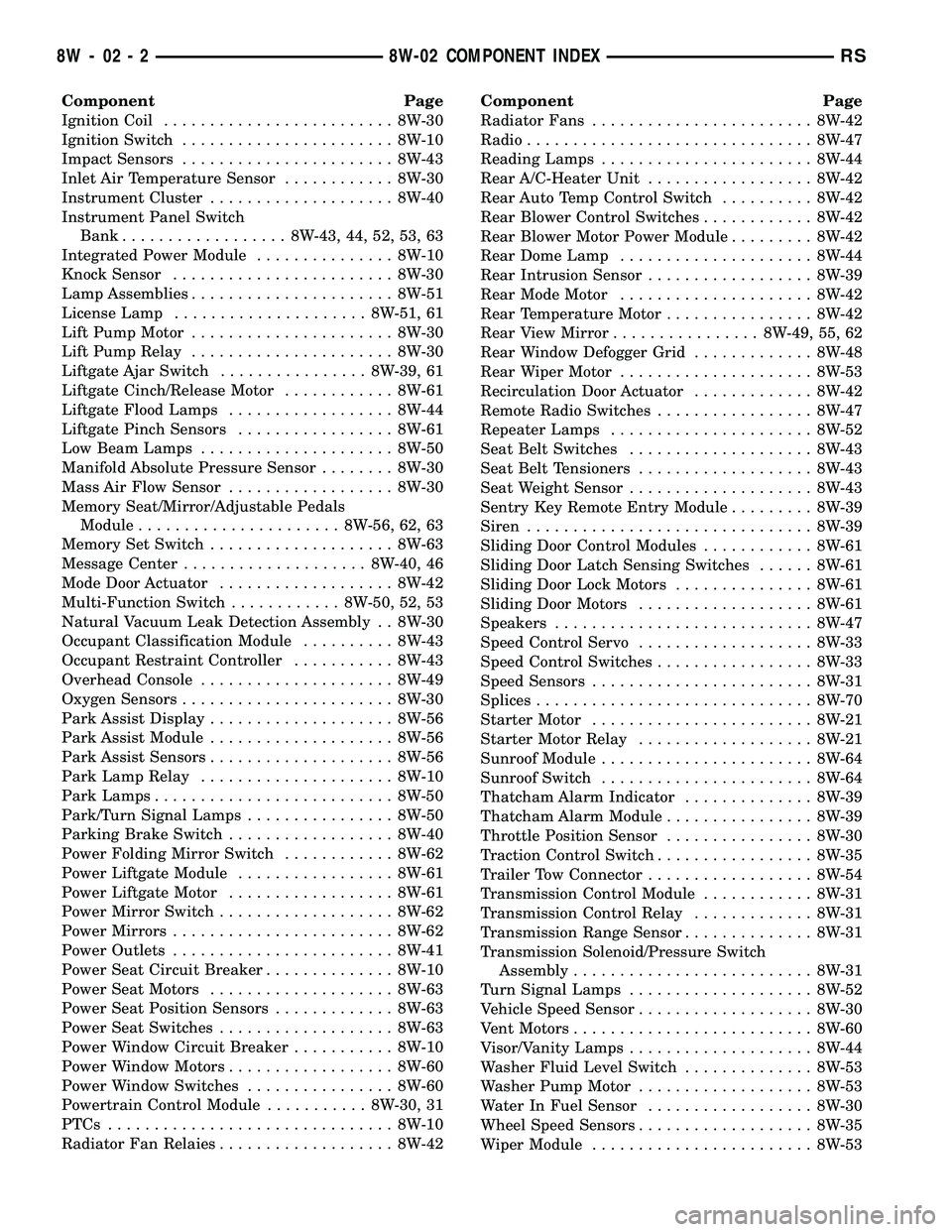
Component Page
Ignition Coil......................... 8W-30
Ignition Switch....................... 8W-10
Impact Sensors....................... 8W-43
Inlet Air Temperature Sensor............ 8W-30
Instrument Cluster.................... 8W-40
Instrument Panel Switch
Bank.................. 8W-43, 44, 52, 53, 63
Integrated Power Module............... 8W-10
Knock Sensor........................ 8W-30
Lamp Assemblies...................... 8W-51
License Lamp..................... 8W-51, 61
Lift Pump Motor...................... 8W-30
Lift Pump Relay...................... 8W-30
Liftgate Ajar Switch................ 8W-39, 61
Liftgate Cinch/Release Motor............ 8W-61
Liftgate Flood Lamps.................. 8W-44
Liftgate Pinch Sensors................. 8W-61
Low Beam Lamps..................... 8W-50
Manifold Absolute Pressure Sensor........ 8W-30
Mass Air Flow Sensor.................. 8W-30
Memory Seat/Mirror/Adjustable Pedals
Module...................... 8W-56, 62, 63
Memory Set Switch.................... 8W-63
Message Center.................... 8W-40, 46
Mode Door Actuator................... 8W-42
Multi-Function Switch............ 8W-50, 52, 53
Natural Vacuum Leak Detection Assembly . . 8W-30
Occupant Classification Module.......... 8W-43
Occupant Restraint Controller........... 8W-43
Overhead Console..................... 8W-49
Oxygen Sensors....................... 8W-30
Park Assist Display.................... 8W-56
Park Assist Module.................... 8W-56
Park Assist Sensors.................... 8W-56
Park Lamp Relay..................... 8W-10
Park Lamps.......................... 8W-50
Park/Turn Signal Lamps................ 8W-50
Parking Brake Switch.................. 8W-40
Power Folding Mirror Switch............ 8W-62
Power Liftgate Module................. 8W-61
Power Liftgate Motor.................. 8W-61
Power Mirror Switch................... 8W-62
Power Mirrors........................ 8W-62
Power Outlets........................ 8W-41
Power Seat Circuit Breaker.............. 8W-10
Power Seat Motors.................... 8W-63
Power Seat Position Sensors............. 8W-63
Power Seat Switches................... 8W-63
Power Window Circuit Breaker........... 8W-10
Power Window Motors.................. 8W-60
Power Window Switches................ 8W-60
Powertrain Control Module........... 8W-30, 31
PTCs............................... 8W-10
Radiator Fan Relaies................... 8W-42Component Page
Radiator Fans........................ 8W-42
Radio............................... 8W-47
Reading Lamps....................... 8W-44
Rear A/C-Heater Unit.................. 8W-42
Rear Auto Temp Control Switch.......... 8W-42
Rear Blower Control Switches............ 8W-42
Rear Blower Motor Power Module......... 8W-42
Rear Dome Lamp..................... 8W-44
Rear Intrusion Sensor.................. 8W-39
Rear Mode Motor..................... 8W-42
Rear Temperature Motor................ 8W-42
Rear View Mirror................ 8W-49, 55, 62
Rear Window Defogger Grid............. 8W-48
Rear Wiper Motor..................... 8W-53
Recirculation Door Actuator............. 8W-42
Remote Radio Switches................. 8W-47
Repeater Lamps...................... 8W-52
Seat Belt Switches.................... 8W-43
Seat Belt Tensioners................... 8W-43
Seat Weight Sensor.................... 8W-43
Sentry Key Remote Entry Module......... 8W-39
Siren............................... 8W-39
Sliding Door Control Modules............ 8W-61
Sliding Door Latch Sensing Switches...... 8W-61
Sliding Door Lock Motors............... 8W-61
Sliding Door Motors................... 8W-61
Speakers............................ 8W-47
Speed Control Servo................... 8W-33
Speed Control Switches................. 8W-33
Speed Sensors........................ 8W-31
Splices.............................. 8W-70
Starter Motor........................ 8W-21
Starter Motor Relay................... 8W-21
Sunroof Module....................... 8W-64
Sunroof Switch....................... 8W-64
Thatcham Alarm Indicator.............. 8W-39
Thatcham Alarm Module................ 8W-39
Throttle Position Sensor................ 8W-30
Traction Control Switch................. 8W-35
Trailer Tow Connector.................. 8W-54
Transmission Control Module............ 8W-31
Transmission Control Relay............. 8W-31
Transmission Range Sensor.............. 8W-31
Transmission Solenoid/Pressure Switch
Assembly.......................... 8W-31
Turn Signal Lamps.................... 8W-52
Vehicle Speed Sensor................... 8W-30
Vent Motors.......................... 8W-60
Visor/Vanity Lamps.................... 8W-44
Washer Fluid Level Switch.............. 8W-53
Washer Pump Motor................... 8W-53
Water In Fuel Sensor.................. 8W-30
Wheel Speed Sensors................... 8W-35
Wiper Module........................ 8W-53
8W - 02 - 2 8W-02 COMPONENT INDEXRS
Page 585 of 2339
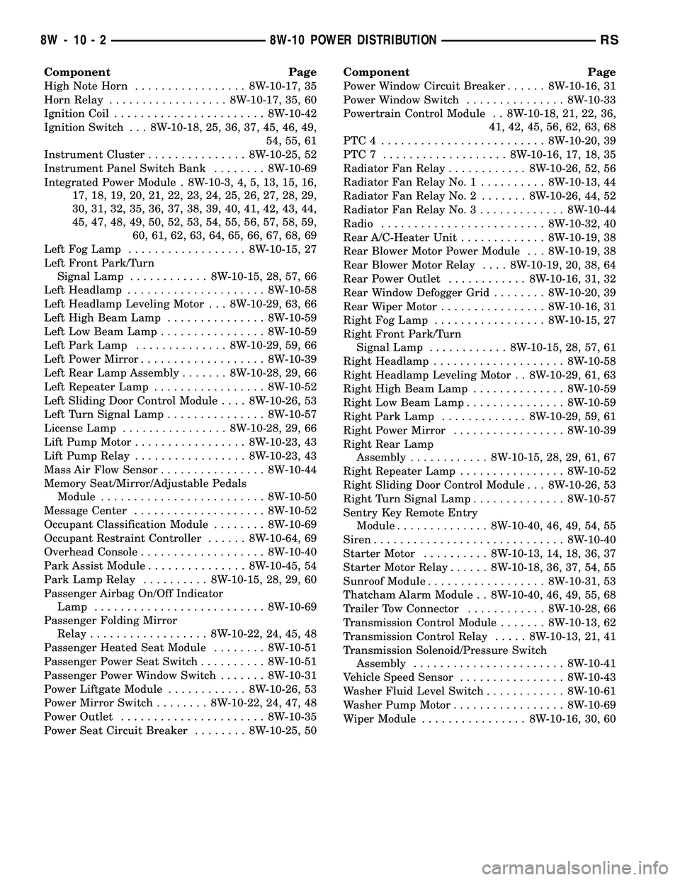
Component Page
High Note Horn................. 8W-10-17, 35
Horn Relay.................. 8W-10-17, 35, 60
Ignition Coil....................... 8W-10-42
Ignition Switch . . . 8W-10-18, 25, 36, 37, 45, 46, 49,
54, 55, 61
Instrument Cluster............... 8W-10-25, 52
Instrument Panel Switch Bank........ 8W-10-69
Integrated Power Module . 8W-10-3, 4, 5, 13, 15, 16,
17, 18, 19, 20, 21, 22, 23, 24, 25, 26, 27, 28, 29,
30, 31, 32, 35, 36, 37, 38, 39, 40, 41, 42, 43, 44,
45, 47, 48, 49, 50, 52, 53, 54, 55, 56, 57, 58, 59,
60, 61, 62, 63, 64, 65, 66, 67, 68, 69
Left Fog Lamp.................. 8W-10-15, 27
Left Front Park/Turn
Signal Lamp............ 8W-10-15, 28, 57, 66
Left Headlamp..................... 8W-10-58
Left Headlamp Leveling Motor . . . 8W-10-29, 63, 66
Left High Beam Lamp............... 8W-10-59
Left Low Beam Lamp................ 8W-10-59
Left Park Lamp.............. 8W-10-29, 59, 66
Left Power Mirror................... 8W-10-39
Left Rear Lamp Assembly....... 8W-10-28, 29, 66
Left Repeater Lamp................. 8W-10-52
Left Sliding Door Control Module.... 8W-10-26, 53
Left Turn Signal Lamp............... 8W-10-57
License Lamp................ 8W-10-28, 29, 66
Lift Pump Motor................. 8W-10-23, 43
Lift Pump Relay................. 8W-10-23, 43
Mass Air Flow Sensor................ 8W-10-44
Memory Seat/Mirror/Adjustable Pedals
Module......................... 8W-10-50
Message Center.................... 8W-10-52
Occupant Classification Module........ 8W-10-69
Occupant Restraint Controller...... 8W-10-64, 69
Overhead Console................... 8W-10-40
Park Assist Module............... 8W-10-45, 54
Park Lamp Relay.......... 8W-10-15, 28, 29, 60
Passenger Airbag On/Off Indicator
Lamp.......................... 8W-10-69
Passenger Folding Mirror
Relay.................. 8W-10-22, 24, 45, 48
Passenger Heated Seat Module........ 8W-10-51
Passenger Power Seat Switch.......... 8W-10-51
Passenger Power Window Switch....... 8W-10-31
Power Liftgate Module............ 8W-10-26, 53
Power Mirror Switch........ 8W-10-22, 24, 47, 48
Power Outlet...................... 8W-10-35
Power Seat Circuit Breaker........ 8W-10-25, 50Component Page
Power Window Circuit Breaker...... 8W-10-16, 31
Power Window Switch............... 8W-10-33
Powertrain Control Module . . 8W-10-18, 21, 22, 36,
41, 42, 45, 56, 62, 63, 68
PTC4 ......................... 8W-10-20, 39
PTC7 ................... 8W-10-16, 17, 18, 35
Radiator Fan Relay............ 8W-10-26, 52, 56
Radiator Fan Relay No. 1.......... 8W-10-13, 44
Radiator Fan Relay No. 2....... 8W-10-26, 44, 52
Radiator Fan Relay No. 3............. 8W-10-44
Radio......................... 8W-10-32, 40
Rear A/C-Heater Unit............. 8W-10-19, 38
Rear Blower Motor Power Module . . . 8W-10-19, 38
Rear Blower Motor Relay.... 8W-10-19, 20, 38, 64
Rear Power Outlet............ 8W-10-16, 31, 32
Rear Window Defogger Grid........ 8W-10-20, 39
Rear Wiper Motor................ 8W-10-16, 31
Right Fog Lamp................. 8W-10-15, 27
Right Front Park/Turn
Signal Lamp............ 8W-10-15, 28, 57, 61
Right Headlamp.................... 8W-10-58
Right Headlamp Leveling Motor . . 8W-10-29, 61, 63
Right High Beam Lamp.............. 8W-10-59
Right Low Beam Lamp............... 8W-10-59
Right Park Lamp............. 8W-10-29, 59, 61
Right Power Mirror................. 8W-10-39
Right Rear Lamp
Assembly............ 8W-10-15, 28, 29, 61, 67
Right Repeater Lamp................ 8W-10-52
Right Sliding Door Control Module . . . 8W-10-26, 53
Right Turn Signal Lamp.............. 8W-10-57
Sentry Key Remote Entry
Module.............. 8W-10-40, 46, 49, 54, 55
Siren............................. 8W-10-40
Starter Motor.......... 8W-10-13, 14, 18, 36, 37
Starter Motor Relay...... 8W-10-18, 36, 37, 54, 55
Sunroof Module.................. 8W-10-31, 53
Thatcham Alarm Module . . 8W-10-40, 46, 49, 55, 68
Trailer Tow Connector............ 8W-10-28, 66
Transmission Control Module....... 8W-10-13, 62
Transmission Control Relay..... 8W-10-13, 21, 41
Transmission Solenoid/Pressure Switch
Assembly....................... 8W-10-41
Vehicle Speed Sensor................ 8W-10-43
Washer Fluid Level Switch............ 8W-10-61
Washer Pump Motor................. 8W-10-69
Wiper Module................ 8W-10-16, 30, 60
8W - 10 - 2 8W-10 POWER DISTRIBUTIONRS
Page 698 of 2339
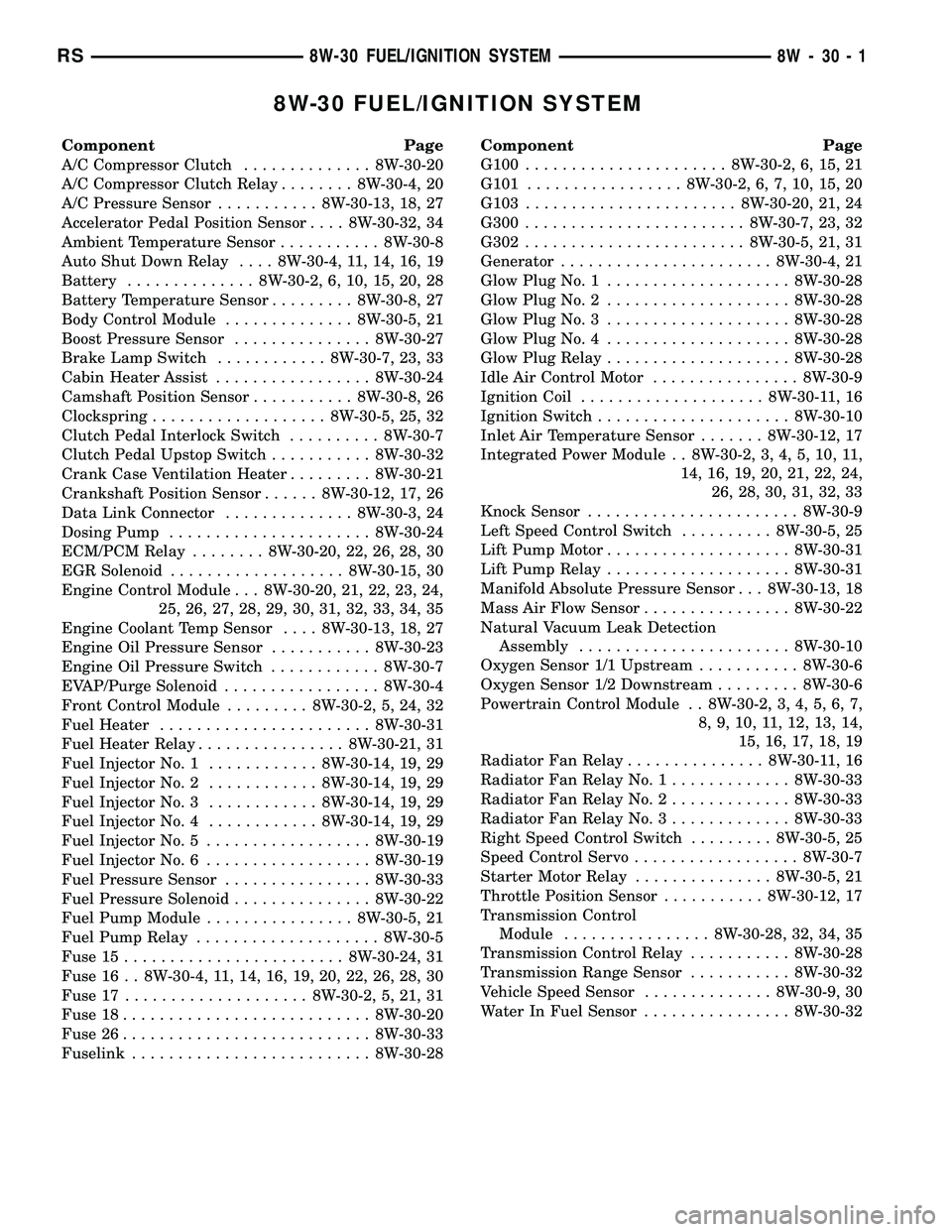
8W-30 FUEL/IGNITION SYSTEM
Component Page
A/C Compressor Clutch.............. 8W-30-20
A/C Compressor Clutch Relay........ 8W-30-4, 20
A/C Pressure Sensor........... 8W-30-13, 18, 27
Accelerator Pedal Position Sensor.... 8W-30-32, 34
Ambient Temperature Sensor........... 8W-30-8
Auto Shut Down Relay.... 8W-30-4, 11, 14, 16, 19
Battery.............. 8W-30-2, 6, 10, 15, 20, 28
Battery Temperature Sensor......... 8W-30-8, 27
Body Control Module.............. 8W-30-5, 21
Boost Pressure Sensor............... 8W-30-27
Brake Lamp Switch............ 8W-30-7, 23, 33
Cabin Heater Assist................. 8W-30-24
Camshaft Position Sensor........... 8W-30-8, 26
Clockspring................... 8W-30-5, 25, 32
Clutch Pedal Interlock Switch.......... 8W-30-7
Clutch Pedal Upstop Switch........... 8W-30-32
Crank Case Ventilation Heater......... 8W-30-21
Crankshaft Position Sensor...... 8W-30-12, 17, 26
Data Link Connector.............. 8W-30-3, 24
Dosing Pump...................... 8W-30-24
ECM/PCM Relay........ 8W-30-20, 22, 26, 28, 30
EGR Solenoid................... 8W-30-15, 30
Engine Control Module . . . 8W-30-20, 21, 22, 23, 24,
25, 26, 27, 28, 29, 30, 31, 32, 33, 34, 35
Engine Coolant Temp Sensor.... 8W-30-13, 18, 27
Engine Oil Pressure Sensor........... 8W-30-23
Engine Oil Pressure Switch............ 8W-30-7
EVAP/Purge Solenoid................. 8W-30-4
Front Control Module......... 8W-30-2, 5, 24, 32
Fuel Heater....................... 8W-30-31
Fuel Heater Relay................ 8W-30-21, 31
Fuel Injector No. 1............ 8W-30-14, 19, 29
Fuel Injector No. 2............ 8W-30-14, 19, 29
Fuel Injector No. 3............ 8W-30-14, 19, 29
Fuel Injector No. 4............ 8W-30-14, 19, 29
Fuel Injector No. 5.................. 8W-30-19
Fuel Injector No. 6.................. 8W-30-19
Fuel Pressure Sensor................ 8W-30-33
Fuel Pressure Solenoid............... 8W-30-22
Fuel Pump Module................ 8W-30-5, 21
Fuel Pump Relay.................... 8W-30-5
Fuse 15........................ 8W-30-24, 31
Fuse 16 . . 8W-30-4, 11, 14, 16, 19, 20, 22, 26, 28, 30
Fuse 17.................... 8W-30-2, 5, 21, 31
Fuse 18........................... 8W-30-20
Fuse 26........................... 8W-30-33
Fuselink.......................... 8W-30-28Component Page
G100...................... 8W-30-2, 6, 15, 21
G101................. 8W-30-2, 6, 7, 10, 15, 20
G103....................... 8W-30-20, 21, 24
G300........................ 8W-30-7, 23, 32
G302........................ 8W-30-5, 21, 31
Generator....................... 8W-30-4, 21
Glow Plug No. 1.................... 8W-30-28
Glow Plug No. 2.................... 8W-30-28
Glow Plug No. 3.................... 8W-30-28
Glow Plug No. 4.................... 8W-30-28
Glow Plug Relay.................... 8W-30-28
Idle Air Control Motor................ 8W-30-9
Ignition Coil.................... 8W-30-11, 16
Ignition Switch..................... 8W-30-10
Inlet Air Temperature Sensor....... 8W-30-12, 17
Integrated Power Module . . 8W-30-2, 3, 4, 5, 10, 11,
14, 16, 19, 20, 21, 22, 24,
26, 28, 30, 31, 32, 33
Knock Sensor....................... 8W-30-9
Left Speed Control Switch.......... 8W-30-5, 25
Lift Pump Motor.................... 8W-30-31
Lift Pump Relay.................... 8W-30-31
Manifold Absolute Pressure Sensor . . . 8W-30-13, 18
Mass Air Flow Sensor................ 8W-30-22
Natural Vacuum Leak Detection
Assembly....................... 8W-30-10
Oxygen Sensor 1/1 Upstream........... 8W-30-6
Oxygen Sensor 1/2 Downstream......... 8W-30-6
Powertrain Control Module . . 8W-30-2, 3, 4, 5, 6, 7,
8, 9, 10, 11, 12, 13, 14,
15, 16, 17, 18, 19
Radiator Fan Relay............... 8W-30-11, 16
Radiator Fan Relay No. 1............. 8W-30-33
Radiator Fan Relay No. 2............. 8W-30-33
Radiator Fan Relay No. 3............. 8W-30-33
Right Speed Control Switch......... 8W-30-5, 25
Speed Control Servo.................. 8W-30-7
Starter Motor Relay............... 8W-30-5, 21
Throttle Position Sensor........... 8W-30-12, 17
Transmission Control
Module................ 8W-30-28, 32, 34, 35
Transmission Control Relay........... 8W-30-28
Transmission Range Sensor........... 8W-30-32
Vehicle Speed Sensor.............. 8W-30-9, 30
Water In Fuel Sensor................ 8W-30-32
RS8W-30 FUEL/IGNITION SYSTEM8W-30-1
Page 972 of 2339

Component Page
Evaporator Temperature Sensor........ 8W-80-70
Floor Console Lamp................. 8W-80-70
Floor Console Power Outlet (Export).... 8W-80-70
Front Blower Module C1 (ATC)........ 8W-80-71
Front Blower Module C2 (ATC)........ 8W-80-71
Front Cigar Lighter................. 8W-80-71
Front Control Module................ 8W-80-72
Front Intrusion Sensor (United
Kingdom)....................... 8W-80-73
Front Reading Lamps/Switch.......... 8W-80-73
Fuel Heater (Diesel)................. 8W-80-73
Fuel Injector No. 1 (2.4L/3.3L/3.8L)..... 8W-80-73
Fuel Injector No. 1 (Diesel)............ 8W-80-73
Fuel Injector No. 2 (2.4L/3.3L/3.8L)..... 8W-80-74
Fuel Injector No. 2 (Diesel)............ 8W-80-74
Fuel Injector No. 3 (2.4L/3.3L/3.8L)..... 8W-80-74
Fuel Injector No. 3 (Diesel)............ 8W-80-74
Fuel Injector No. 4 (2.4L/3.3L/3.8L)..... 8W-80-75
Fuel Injector No. 4 (Diesel)............ 8W-80-75
Fuel Injector No. 5 (3.3L/3.8L)......... 8W-80-75
Fuel Injector No. 6 (3.3L/3.8L)......... 8W-80-75
Fuel Pressure Sensor (Diesel).......... 8W-80-76
Fuel Pressure Solenoid (Diesel)........ 8W-80-76
Fuel Pump Module.................. 8W-80-76
Generator......................... 8W-80-76
Glow Plug Relay (Diesel)............. 8W-80-77
Hands Free Module C1............... 8W-80-77
Hands Free Module C2............... 8W-80-77
Hands Free Module C3............... 8W-80-78
Headlamp Switch................... 8W-80-78
Headlamp Washer Pump Motor (Export) . 8W-80-78
High Note Horn.................... 8W-80-79
Hood Ajar Switch (Export)............ 8W-80-79
Idle Air Control Motor (Gas)........... 8W-80-79
Ignition Coil (2.4L).................. 8W-80-79
Ignition Coil (3.3L/3.8L).............. 8W-80-80
Ignition Switch..................... 8W-80-80
Inlet Air Temperature Sensor.......... 8W-80-80
Input Speed Sensor................. 8W-80-80
Instrument Cluster.................. 8W-80-81
Instrument Panel Switch Bank
(Except Heated Seats)............. 8W-80-81
Instrument Panel Switch Bank
(Heated Seats)................... 8W-80-81
Integrated Power Module C1.......... 8W-80-82
Integrated Power Module C2.......... 8W-80-82
Integrated Power Module C3.......... 8W-80-83
Integrated Power Module C4.......... 8W-80-83
Integrated Power Module C5.......... 8W-80-84
Integrated Power Module C6.......... 8W-80-84
Integrated Power Module C7.......... 8W-80-84
Integrated Power Module C8.......... 8W-80-85
Integrated Power Module C9.......... 8W-80-85
Knock Sensor (Except Export)......... 8W-80-85Component Page
Left B-Pillar Switch (Power Sliding
Door).......................... 8W-80-86
Left Cinch/Release Motor (Power Sliding
Door).......................... 8W-80-86
Left Curtain Airbag Squib............ 8W-80-86
Left Cylinder Lock Switch (Export)..... 8W-80-86
Left Door Speaker.................. 8W-80-87
Left Fog Lamp..................... 8W-80-87
Left Front Door Ajar Switch (Base)..... 8W-80-87
Left Front Door Lock Motor/Ajar Switch
(Except Base).................... 8W-80-87
Left Front Impact Sensor (Export)...... 8W-80-87
Left Front Impact Sensor (Except
Export)......................... 8W-80-88
Left Front Park/Turn Signal Lamp...... 8W-80-88
Left Front Wheel Speed Sensor........ 8W-80-88
Left Full Open Switch (Power Sliding
Door).......................... 8W-80-88
Left Headlamp (Caravan/Voyager Except
Export)......................... 8W-80-89
Left Headlamp (Town And Country)..... 8W-80-89
Left Headlamp Leveling Motor (Export) . . 8W-80-89
Left High Beam Lamp (Export)........ 8W-80-89
Left Instrument Panel Speaker........ 8W-80-90
Left Liftgate Flood Lamp (Export)...... 8W-80-90
Left Low Beam Lamp (Export)......... 8W-80-90
Left Mid Reading Lamp (Premium/
Luxury)........................ 8W-80-90
Left Park Lamp (Export)............. 8W-80-91
Left Power Mirror................... 8W-80-91
Left Rear Lamp Assembly............ 8W-80-91
Left Rear Pillar Speaker (Highline
Audio).......................... 8W-80-92
Left Rear Reading Lamp (Luxury)...... 8W-80-92
Left Rear Speaker.................. 8W-80-92
Left Rear Vent Motor................ 8W-80-92
Left Rear Wheel Speed Sensor......... 8W-80-93
Left Remote Radio Switch............ 8W-80-93
Left Repeater Lamp (Export).......... 8W-80-93
Left Side Impact Sensor 1 (Export)..... 8W-80-93
Left Side Impact Sensor 1 (Except
Export)......................... 8W-80-94
Left Side Impact Sensor 2............ 8W-80-94
Left Side Impact Sensor 3............ 8W-80-94
Left Sliding Door Control Module C1
(Power Sliding Door).............. 8W-80-94
Left Sliding Door Control Module C2
(Power Sliding Door).............. 8W-80-95
Left Sliding Door Latch Sensing Switch
(Power Sliding Door).............. 8W-80-95
Left Sliding Door Lock Motor (Power Sliding
Door).......................... 8W-80-95
Left Sliding Door Lock Motor/Ajar Switch
(Manual Sliding Door)............. 8W-80-96
RS8W-80 CONNECTOR PIN-OUTS8W-80-3