maintenance schedule CHRYSLER VOYAGER 2005 Owner's Manual
[x] Cancel search | Manufacturer: CHRYSLER, Model Year: 2005, Model line: VOYAGER, Model: CHRYSLER VOYAGER 2005Pages: 2339, PDF Size: 59.69 MB
Page 37 of 2339
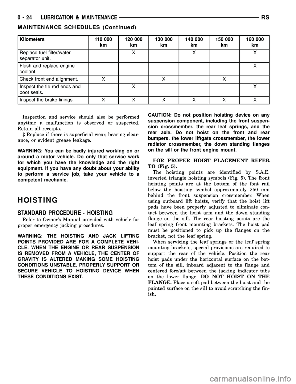
Kilometers 110 000
km120 000
km130 000
km140 000
km150 000
km160 000
km
Replace fuel filter/water
separator unit.XX X
Flush and replace engine
coolant.X
Check front end alignment. X X X
Inspect the tie rod ends and
boot seals.XX
Inspect the brake linings. XXXXX X
Inspection and service should also be performed
anytime a malfunction is observed or suspected.
Retain all receipts.
³ Replace if there is superficial wear, bearing clear-
ance, or evident grease leakage.
WARNING: You can be badly injured working on or
around a motor vehicle. Do only that service work
for which you have the knowledge and the right
equipment. If you have any doubt about your ability
to perform a service job, take your vehicle to a
competent mechanic.
HOISTING
STANDARD PROCEDURE - HOISTING
Refer to Owner's Manual provided with vehicle for
proper emergency jacking procedures.
WARNING: THE HOISTING AND JACK LIFTING
POINTS PROVIDED ARE FOR A COMPLETE VEHI-
CLE. WHEN THE ENGINE OR REAR SUSPENSION
IS REMOVED FROM A VEHICLE, THE CENTER OF
GRAVITY IS ALTERED MAKING SOME HOISTING
CONDITIONS UNSTABLE. PROPERLY SUPPORT OR
SECURE VEHICLE TO HOISTING DEVICE WHEN
THESE CONDITIONS EXIST.CAUTION: Do not position hoisting device on any
suspension component, including the front suspen-
sion crossmember, the rear leaf springs, and the
rear axle. Do not hoist on the front and rear
bumpers, the lower liftgate crossmember, the lower
radiator crossmember, the down standing flanges
on the sill or the front engine mount.
FOR PROPER HOIST PLACEMENT REFER
TO (Fig. 5).
The hoisting points are identified by S.A.E.
inverted triangle hoisting symbols (Fig. 5). The front
hoisting points are at the bottom of the font rail
below the hoisting symbol approximately 250 mm
behind the front suspension crossmember. When
using outboard lift hoists, verify that the hoist lift
pads have been properly adjusted to eliminate con-
tact between the hoist arm and the down standing
flange on the sill. The rear hoisting points are the
leaf spring front mounting brackets. The hoist pad
must be positioned to pick up the flanges on the
bracket, not the leaf spring.
When servicing the leaf springs or the leaf spring
mounting brackets, special provisions are required to
support the rear of the vehicle. Position the rear
hoist pads under the horizontal surface on the bot-
tom of the sill, inboard adjacent to the flange and
centered fore/aft between the jacking indicator tabs
on the lower flange.DO NOT HOIST ON THE
FLANGE.Place a soft pad between the hoist and the
painted surface on the sill to avoid scratching the fin-
ish.
0 - 24 LUBRICATION & MAINTENANCERS
MAINTENANCE SCHEDULES (Continued)
Page 238 of 2339
COOLANT
DESCRIPTION - ENGINE COOLANT
WARNING: ANTIFREEZE IS AN ETHYLENE GLYCOL
BASE COOLANT AND IS HARMFUL IF SWAL-
LOWED OR INHALED. IF SWALLOWED, DRINK
TWO GLASSES OF WATER AND INDUCE VOMIT-
ING. IF INHALED, MOVE TO FRESH AIR AREA.
SEEK MEDICAL ATTENTION IMMEDIATELY. DO NOT
STORE IN OPEN OR UNMARKED CONTAINERS.
WASH SKIN AND CLOTHING THOROUGHLY AFTER
COMING IN CONTACT WITH ETHYLENE GLYCOL.
KEEP OUT OF REACH OF CHILDREN. DISPOSE OF
GLYCOL BASE COOLANT PROPERLY, CONTACT
YOUR DEALER OR GOVERNMENT AGENCY FOR
LOCATION OF COLLECTION CENTER IN YOUR
AREA. DO NOT OPEN A COOLING SYSTEM WHEN
THE ENGINE IS AT OPERATING TEMPERATURE OR
HOT UNDER PRESSURE, PERSONAL INJURY CAN
RESULT. AVOID RADIATOR COOLING FAN WHEN
ENGINE COMPARTMENT RELATED SERVICE IS
PERFORMED, PERSONAL INJURY CAN RESULT.
CAUTION: Use of Propylene Glycol based coolants
is not recommended, as they provide less freeze
protection and less boiling protection.
The cooling system is designed around the coolant.
The coolant must accept heat from engine metal, in
the cylinder head area near the exhaust valves and
engine block. Then coolant carries the heat to the
radiator where the tube/fin radiator can transfer the
heat to the air.
The use of aluminum cylinder blocks, cylinder
heads, and water pumps requires special corrosion
protection. MopartAntifreeze/Coolant, 5
Year/100,000 Mile Formula (MS-9769), or the equiva-
lent ethylene glycol base coolant with hybrid organic
corrosion inhibitors (called HOAT, for Hybrid Organic
Additive Technology) is recommended. This coolant
offers the best engine cooling without corrosion when
mixed with 50% Ethylene Glycol and 50% distilled
water to obtain a freeze point of -37ÉC (-35ÉF). If it
loses color or becomes contaminated, drain, flush,
and replace with fresh properly mixed coolant solu-
tion.
The green coolantMUST NOT BE MIXEDwith
the orange or magenta coolants. When replacing cool-
ant the complete system flush must be performed
before using the replacement coolant.CAUTION: MoparTAntifreeze/Coolant, 5
Year/100,000 Mile Formula (MS-9769) may not be
mixed with any other type of antifreeze. Doing so
will reduce the corrosion protection and may result
in premature water pump seal failure. If non-HOAT
coolant is introduced into the cooling system in an
emergency, it should be replaced with the specified
coolant as soon as possible.
DIAGNOSIS AND TESTING - COOLANT
CONCENTRATION TESTING
Coolant concentration should be checked when any
additional coolant was added to system or after a
coolant drain, flush and refill. The coolant mixture
offers optimum engine cooling and protection against
corrosion when mixed to a freeze point of -37ÉC
(-34ÉF) to -46ÉC (-50ÉF). The use of a hydrometer or a
refractometer can be used to test coolant concentra-
tion.
A hydrometer will test the amount of glycol in a
mixture by measuring the specific gravity of the mix-
ture. The higher the concentration of ethylene glycol,
the larger the number of balls that will float, and
higher the freeze protection (up to a maximum of
60% by volume glycol).
A refractometer (Special Tool 8286)(Refer to 7 -
COOLING - SPECIAL TOOLS) will test the amount
of glycol in a coolant mixture by measuring the
amount a beam of light bends as it passes through
the fluid.
Some coolant manufactures use other types of gly-
cols into their coolant formulations. Propylene glycol
is the most common new coolant. However, propylene
glycol based coolants do not provide the same freez-
ing protection and corrosion protection and is not rec-
ommended.
CAUTION: Do not mix types of coolantÐcorrosion
protection will be severely reduced.
STANDARD PROCEDURE - COOLANT SERVICE
For engine coolant recommended service schedule,
(Refer to LUBRICATION & MAINTENANCE/MAIN-
TENANCE SCHEDULES - DESCRIPTION).
RSENGINE7-19
Page 310 of 2339
CLEANING
The following information details the recommended
cleaning procedures for the battery and related com-
ponents. In addition to the maintenance schedules
found in this service manual and the owner's man-
ual, it is recommended that these procedures be per-
formed any time the battery or related components
must be removed for vehicle service.
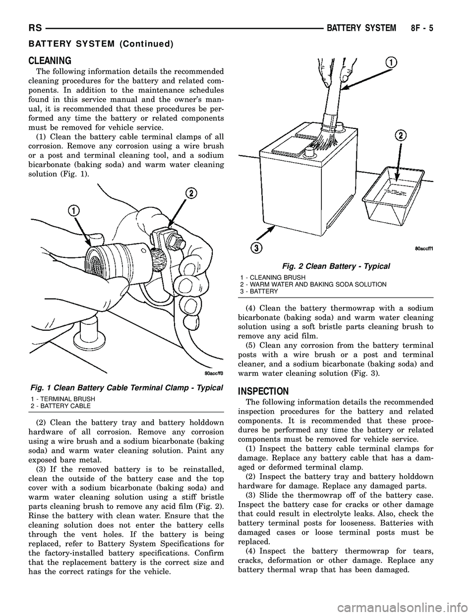
(1) Clean the battery cable terminal clamps of all
corrosion. Remove any corrosion using a wire brush
or a post and terminal cleaning tool, and a sodium
bicarbonate (baking soda) and warm water cleaning
solution (Fig. 1).
(2) Clean the battery tray and battery holddown
hardware of all corrosion. Remove any corrosion
using a wire brush and a sodium bicarbonate (baking
soda) and warm water cleaning solution. Paint any
exposed bare metal.
(3) If the removed battery is to be reinstalled,
clean the outside of the battery case and the top
cover with a sodium bicarbonate (baking soda) and
warm water cleaning solution using a stiff bristle
parts cleaning brush to remove any acid film (Fig. 2).
Rinse the battery with clean water. Ensure that the
cleaning solution does not enter the battery cells
through the vent holes. If the battery is being
replaced, refer to Battery System Specifications for
the factory-installed battery specifications. Confirm
that the replacement battery is the correct size and
has the correct ratings for the vehicle.(4) Clean the battery thermowrap with a sodium
bicarbonate (baking soda) and warm water cleaning
solution using a soft bristle parts cleaning brush to
remove any acid film.
(5) Clean any corrosion from the battery terminal
posts with a wire brush or a post and terminal
cleaner, and a sodium bicarbonate (baking soda) and
warm water cleaning solution (Fig. 3).
INSPECTION
The following information details the recommended
inspection procedures for the battery and related
components. It is recommended that these proce-
dures be performed any time the battery or related
components must be removed for vehicle service.
(1) Inspect the battery cable terminal clamps for
damage. Replace any battery cable that has a dam-
aged or deformed terminal clamp.
(2) Inspect the battery tray and battery holddown
hardware for damage. Replace any damaged parts.
(3) Slide the thermowrap off of the battery case.
Inspect the battery case for cracks or other damage
that could result in electrolyte leaks. Also, check the
battery terminal posts for looseness. Batteries with
damaged cases or loose terminal posts must be
replaced.
(4) Inspect the battery thermowrap for tears,
cracks, deformation or other damage. Replace any
battery thermal wrap that has been damaged.
Fig. 1 Clean Battery Cable Terminal Clamp - Typical
1 - TERMINAL BRUSH
2 - BATTERY CABLE
Fig. 2 Clean Battery - Typical
1 - CLEANING BRUSH
2 - WARM WATER AND BAKING SODA SOLUTION
3 - BATTERY
RSBATTERY SYSTEM8F-5
BATTERY SYSTEM (Continued)
Page 1231 of 2339
(6) Install oil pressure switch and connector. (Refer
to 9 - ENGINE/LUBRICATION/OIL PRESSURE
SENSOR/SWITCH - INSTALLATION)
OIL
STANDARD PROCEDURE
ENGINE OIL LEVEL CHECK
The best time to check engine oil level is after it
has sat overnight, or if the engine has been running,
allow the engine to be shut off for at least 5 minutes
before checking oil level.
Checking the oil while the vehicle is on level
ground will improve the accuracy of the oil level
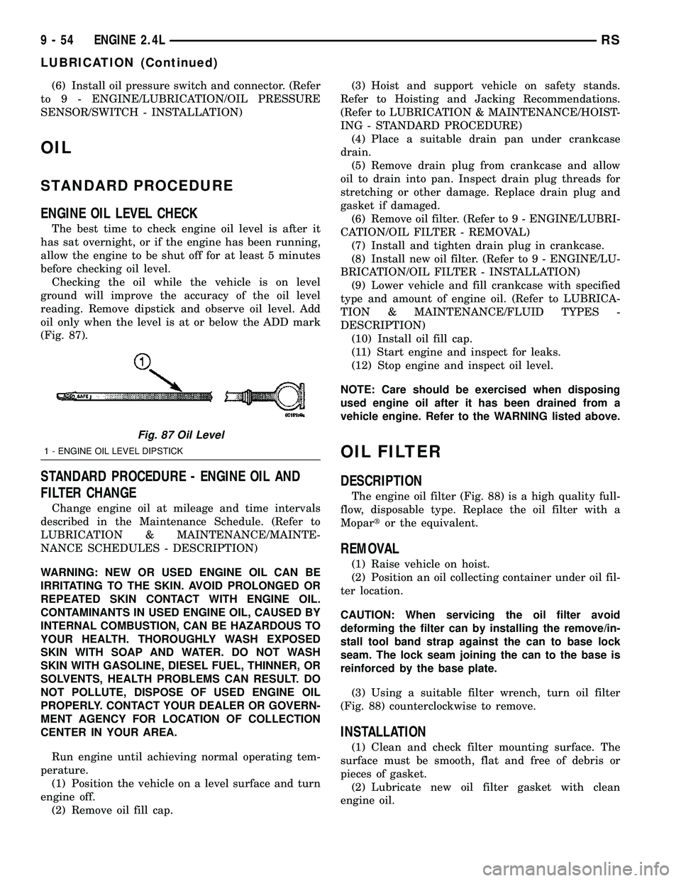
reading. Remove dipstick and observe oil level. Add
oil only when the level is at or below the ADD mark
(Fig. 87).
STANDARD PROCEDURE - ENGINE OIL AND
FILTER CHANGE
Change engine oil at mileage and time intervals
described in the Maintenance Schedule. (Refer to
LUBRICATION & MAINTENANCE/MAINTE-
NANCE SCHEDULES - DESCRIPTION)
WARNING: NEW OR USED ENGINE OIL CAN BE
IRRITATING TO THE SKIN. AVOID PROLONGED OR
REPEATED SKIN CONTACT WITH ENGINE OIL.
CONTAMINANTS IN USED ENGINE OIL, CAUSED BY
INTERNAL COMBUSTION, CAN BE HAZARDOUS TO
YOUR HEALTH. THOROUGHLY WASH EXPOSED
SKIN WITH SOAP AND WATER. DO NOT WASH
SKIN WITH GASOLINE, DIESEL FUEL, THINNER, OR
SOLVENTS, HEALTH PROBLEMS CAN RESULT. DO
NOT POLLUTE, DISPOSE OF USED ENGINE OIL
PROPERLY. CONTACT YOUR DEALER OR GOVERN-
MENT AGENCY FOR LOCATION OF COLLECTION
CENTER IN YOUR AREA.
Run engine until achieving normal operating tem-
perature.
(1) Position the vehicle on a level surface and turn
engine off.
(2) Remove oil fill cap.(3) Hoist and support vehicle on safety stands.
Refer to Hoisting and Jacking Recommendations.
(Refer to LUBRICATION & MAINTENANCE/HOIST-
ING - STANDARD PROCEDURE)
(4) Place a suitable drain pan under crankcase
drain.
(5) Remove drain plug from crankcase and allow
oil to drain into pan. Inspect drain plug threads for
stretching or other damage. Replace drain plug and
gasket if damaged.
(6) Remove oil filter. (Refer to 9 - ENGINE/LUBRI-
CATION/OIL FILTER - REMOVAL)
(7) Install and tighten drain plug in crankcase.
(8) Install new oil filter. (Refer to 9 - ENGINE/LU-
BRICATION/OIL FILTER - INSTALLATION)
(9) Lower vehicle and fill crankcase with specified
type and amount of engine oil. (Refer to LUBRICA-
TION & MAINTENANCE/FLUID TYPES -
DESCRIPTION)
(10) Install oil fill cap.
(11) Start engine and inspect for leaks.
(12) Stop engine and inspect oil level.
NOTE: Care should be exercised when disposing
used engine oil after it has been drained from a
vehicle engine. Refer to the WARNING listed above.
OIL FILTER
DESCRIPTION
The engine oil filter (Fig. 88) is a high quality full-
flow, disposable type. Replace the oil filter with a
Mopartor the equivalent.
REMOVAL
(1) Raise vehicle on hoist.
(2) Position an oil collecting container under oil fil-
ter location.
CAUTION: When servicing the oil filter avoid
deforming the filter can by installing the remove/in-
stall tool band strap against the can to base lock
seam. The lock seam joining the can to the base is
reinforced by the base plate.
(3) Using a suitable filter wrench, turn oil filter
(Fig. 88) counterclockwise to remove.
INSTALLATION
(1) Clean and check filter mounting surface. The
surface must be smooth, flat and free of debris or
pieces of gasket.
(2) Lubricate new oil filter gasket with clean
engine oil.
Fig. 87 Oil Level
1 - ENGINE OIL LEVEL DIPSTICK
9 - 54 ENGINE 2.4LRS
LUBRICATION (Continued)
Page 1316 of 2339
OIL
STANDARD PROCEDURE
STANDARD PROCEDURE - ENGINE OIL AND
FILTER CHANGE
Change engine oil at mileage and time intervals
described in the Maintenance Schedule. (Refer to
LUBRICATION & MAINTENANCE/MAINTE-
NANCE SCHEDULES - DESCRIPTION)
WARNING: NEW OR USED ENGINE OIL CAN BE
IRRITATING TO THE SKIN. AVOID PROLONGED OR
REPEATED SKIN CONTACT WITH ENGINE OIL.
CONTAMINANTS IN USED ENGINE OIL, CAUSED BY
INTERNAL COMBUSTION, CAN BE HAZARDOUS TO
YOUR HEALTH. THOROUGHLY WASH EXPOSED
SKIN WITH SOAP AND WATER. DO NOT WASH
SKIN WITH GASOLINE, DIESEL FUEL, THINNER, OR
SOLVENTS, HEALTH PROBLEMS CAN RESULT. DO
NOT POLLUTE, DISPOSE OF USED ENGINE OIL
PROPERLY. CONTACT YOUR DEALER OR GOVERN-
MENT AGENCY FOR LOCATION OF COLLECTION
CENTER IN YOUR AREA.Run engine until achieving normal operating tem-
perature.
(1) Position the vehicle on a level surface and turn
engine off.
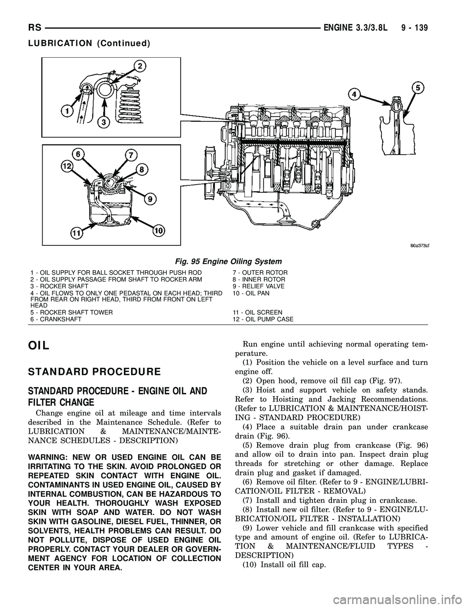
(2) Open hood, remove oil fill cap (Fig. 97).
(3) Hoist and support vehicle on safety stands.
Refer to Hoisting and Jacking Recommendations.
(Refer to LUBRICATION & MAINTENANCE/HOIST-
ING - STANDARD PROCEDURE)
(4) Place a suitable drain pan under crankcase
drain (Fig. 96).
(5) Remove drain plug from crankcase (Fig. 96)
and allow oil to drain into pan. Inspect drain plug
threads for stretching or other damage. Replace
drain plug and gasket if damaged.
(6) Remove oil filter. (Refer to 9 - ENGINE/LUBRI-
CATION/OIL FILTER - REMOVAL)
(7) Install and tighten drain plug in crankcase.
(8) Install new oil filter. (Refer to 9 - ENGINE/LU-
BRICATION/OIL FILTER - INSTALLATION)
(9) Lower vehicle and fill crankcase with specified
type and amount of engine oil. (Refer to LUBRICA-
TION & MAINTENANCE/FLUID TYPES -
DESCRIPTION)
(10) Install oil fill cap.
Fig. 95 Engine Oiling System
1 - OIL SUPPLY FOR BALL SOCKET THROUGH PUSH ROD 7 - OUTER ROTOR
2 - OIL SUPPLY PASSAGE FROM SHAFT TO ROCKER ARM 8 - INNER ROTOR
3 - ROCKER SHAFT 9 - RELIEF VALVE
4 - OIL FLOWS TO ONLY ONE PEDASTAL ON EACH HEAD; THIRD
FROM REAR ON RIGHT HEAD, THIRD FROM FRONT ON LEFT
HEAD10 - OIL PAN
5 - ROCKER SHAFT TOWER 11 - OIL SCREEN
6 - CRANKSHAFT 12 - OIL PUMP CASE
RSENGINE 3.3/3.8L9 - 139
LUBRICATION (Continued)
Page 1543 of 2339
FLUID
STANDARD PROCEDURE
FLUID LEVEL AND CONDITION CHECK
NOTE: Only transmission fluid of the type labeled
Mopar ATF+4 (Automatic Transmission Fluid)
should be used in this transaxle.
FLUID LEVEL CHECK
The transmission sump has a fluid level indicator
(dipstick) to check oil similar to most automatic
transmissions. It is located on the left side of the
engine. Be sure to wipe all dirt from dipstick handle
before removing.
The torque converter fills in both the P Park and N
Neutral positions. Place the selector lever in P Park
to be sure that the fluid level check is accurate.The
engine should be running at idle speed for at
least one minute, with the vehicle on level
ground.At normal operating temperature 82É C
(180É F), the fluid level is correct if it is in the HOT
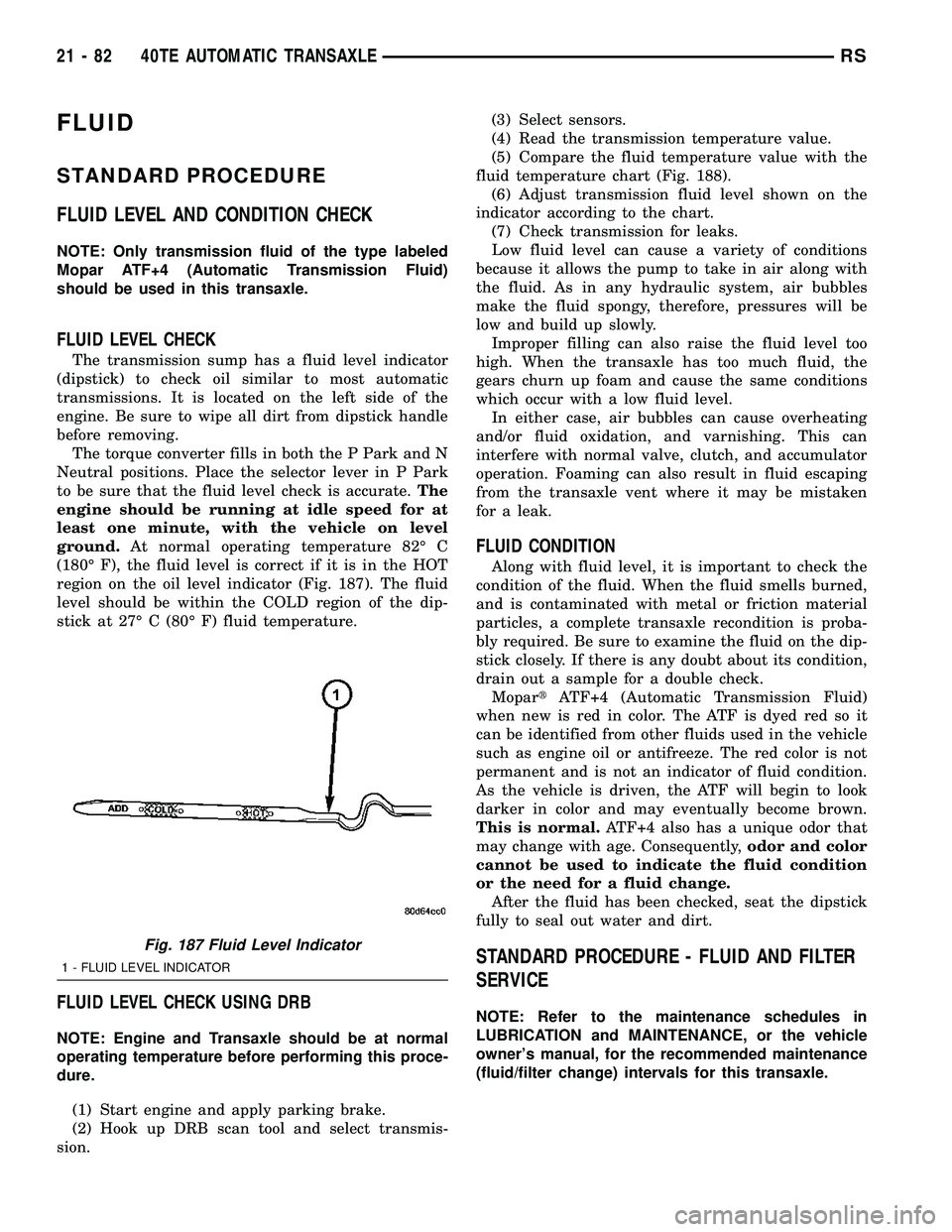
region on the oil level indicator (Fig. 187). The fluid
level should be within the COLD region of the dip-
stick at 27É C (80É F) fluid temperature.
FLUID LEVEL CHECK USING DRB
NOTE: Engine and Transaxle should be at normal
operating temperature before performing this proce-
dure.
(1) Start engine and apply parking brake.
(2) Hook up DRB scan tool and select transmis-
sion.(3) Select sensors.
(4) Read the transmission temperature value.
(5) Compare the fluid temperature value with the
fluid temperature chart (Fig. 188).
(6) Adjust transmission fluid level shown on the
indicator according to the chart.
(7) Check transmission for leaks.
Low fluid level can cause a variety of conditions
because it allows the pump to take in air along with
the fluid. As in any hydraulic system, air bubbles
make the fluid spongy, therefore, pressures will be
low and build up slowly.
Improper filling can also raise the fluid level too
high. When the transaxle has too much fluid, the
gears churn up foam and cause the same conditions
which occur with a low fluid level.
In either case, air bubbles can cause overheating
and/or fluid oxidation, and varnishing. This can
interfere with normal valve, clutch, and accumulator
operation. Foaming can also result in fluid escaping
from the transaxle vent where it may be mistaken
for a leak.
FLUID CONDITION
Along with fluid level, it is important to check the
condition of the fluid. When the fluid smells burned,
and is contaminated with metal or friction material
particles, a complete transaxle recondition is proba-
bly required. Be sure to examine the fluid on the dip-
stick closely. If there is any doubt about its condition,
drain out a sample for a double check.
MopartATF+4 (Automatic Transmission Fluid)
when new is red in color. The ATF is dyed red so it
can be identified from other fluids used in the vehicle
such as engine oil or antifreeze. The red color is not
permanent and is not an indicator of fluid condition.
As the vehicle is driven, the ATF will begin to look
darker in color and may eventually become brown.
This is normal.ATF+4 also has a unique odor that
may change with age. Consequently,odor and color
cannot be used to indicate the fluid condition
or the need for a fluid change.
After the fluid has been checked, seat the dipstick
fully to seal out water and dirt.
STANDARD PROCEDURE - FLUID AND FILTER
SERVICE
NOTE: Refer to the maintenance schedules in
LUBRICATION and MAINTENANCE, or the vehicle
owner's manual, for the recommended maintenance
(fluid/filter change) intervals for this transaxle.
Fig. 187 Fluid Level Indicator
1 - FLUID LEVEL INDICATOR
21 - 82 40TE AUTOMATIC TRANSAXLERS
Page 1692 of 2339
stick closely. If there is any doubt about its condition,
drain out a sample for a double check.
MopartATF+4 (Automatic Transmission Fluid)
when new is red in color. The ATF is dyed red so it
can be identified from other fluids used in the vehicle
such as engine oil or antifreeze. The red color is not
permanent and is not an indicator of fluid condition.
As the vehicle is driven, the ATF will begin to look
darker in color and may eventually become brown.
This is normal.ATF+4 also has a unique odor that
may change with age. Consequently,odor and color
cannot be used to indicate the fluid condition
or the need for a fluid change.
After the fluid has been checked, seat the dipstick
fully to seal out water and dirt.STANDARD PROCEDURE - FLUID AND FILTER
SERVICE
NOTE: Refer to the maintenance schedules in
LUBRICATION and MAINTENANCE, or the vehicle
owner's manual, for the recommended maintenance
(fluid/filter change) intervals for this transaxle.
NOTE: Only fluids of the type labeled MoparTATF+4
(Automatic Transmission Fluid) should be used. A
filter change should be made at the time of the
transmission oil change. The magnet (on the inside
of the oil pan) should also be cleaned with a clean,
dry cloth.
NOTE: If the transaxle is disassembled for any rea-
son, the fluid and filter should be changed.
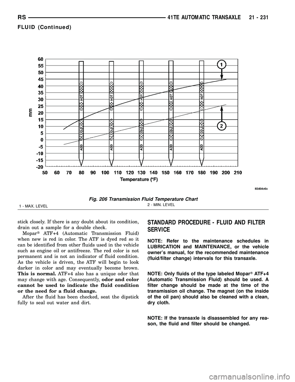
Fig. 206 Transmission Fluid Temperature Chart
1 - MAX. LEVEL2 - MIN. LEVEL
RS41TE AUTOMATIC TRANSAXLE21 - 231
FLUID (Continued)