mirror CHRYSLER VOYAGER 2005 Owner's Manual
[x] Cancel search | Manufacturer: CHRYSLER, Model Year: 2005, Model line: VOYAGER, Model: CHRYSLER VOYAGER 2005Pages: 2339, PDF Size: 59.69 MB
Page 456 of 2339
self-resetting circuit breaker to protect them from
overload. However, consecutive or frequent resetting
of the circuit breaker must not be allowed to con-
tinue, or the motor may be damaged.
MEMORY SYSTEM
The Memory Seat Mirror Module (MSMM) receives
battery current through fuse #22 in the Integrated
Power Module (IPM) and the power seat system cir-
cuit breaker, located under the driver side front seat
near the rear edge of the seat cushion pan. The mem-
ory system does not operate with the Ignition-Off
Draw (IOD) fuse removed. The MSMM will drive a
maximum of 2 motors at a time in a given direction.
If conflicting directions are requested, the priority for
response will be approximately as follows:
²Seat Track Rearward or Forward
²Seat Front Down or Up
²Seat Rear Down or Up
²Recliner Rearward or Forward
The inputs from these switches to the MSMM is a
current limited battery source fed by the MSMM.
This protects the MSMM printed circuit board traces
from acting as fuses. All of these switch contact
inputs to the MSMM are normally closed to ground,
except when actuated.
For diagnosis of the MSMM, the Programmable
Communication Interface (PCI) data bus, or the other
electronic modules on the PCI data bus that provide
inputs and outputs for the memory system, the use of
a DRBIIItor equivalent scan tool and the proper
Diagnostic Procedures information is recommended.
ELECTRONIC VEHICLE INFORMATION CENTER
The Electronic Vehicle Information Center (EVIC)
serves as the user interface for the memory system.
It displays memory system status messages and pro-
vides the user with the means for enabling and dis-
abling the many customer programmable features
available on the vehicle, including those for the mem-
ory system.
(Refer to 8 - ELECTRICAL/OVERHEAD CON-
SOLE/ELECTRONIC VEHICLE INFO CENTER -
DESCRIPTION) for additional information on the
EVIC.
DIAGNOSIS AND TESTING
POWER SEAT SYSTEM
Following are tests that will help to diagnose the
hard wired components and circuits of the power seat
system. However, if the vehicle is also equipped with
the optional memory system, these tests may not
prove conclusive in the diagnosis of the driver side
power seat. In order to obtain conclusive testing ofthe driver side power seat with the memory system
option, the Programmable Communications Interface
(PCI) data bus network and all of the electronic mod-
ules that provide inputs to, or receive outputs from
the memory system components must be checked,
(Refer to 8 - ELECTRICAL/POWER SEATS - DIAG-
NOSIS AND TESTING).
WARNING: SOME VEHICLES ARE EQUIPPED WITH
SEATBACK MOUNTED AIRBAGS. BEFORE
ATTEMPTING TO DIAGNOSE OR SERVICE ANY
SEAT OR POWER SEAT SYSTEM COMPONENT
YOU MUST FIRST DISCONNECT AND ISOLATE THE
BATTERY NEGATIVE CABLE. THEN WAIT TWO MIN-
UTES FOR THE SYSTEM CAPACITOR TO DIS-
CHARGE BEFORE FURTHER SYSTEM SERVICE.
THIS IS THE ONLY SURE WAY TO DISABLE THE
AIRBAG SYSTEM. FAILURE TO DO SO COULD
RESULT IN ACCIDENTAL AIRBAG DEPLOYMENT
AND POSSIBLE PERSONAL INJURY.
(1) If either power seat is completely inoperable,
check the power seat circuit breaker, located under
the trailing edge of the driver side power seat. If the
power seat circuit breaker is OK, continue to the
next step.
(2) Check for proper battery and ground connec-
tions at the power seat switch and/or memory seat
module. Repair any wiring as necessary.
(3) Check the power seat system wire harness con-
nections and pins to ensure proper circuit continuity
and ground paths.
MEMORY SYSTEM
In order to obtain conclusive testing of the memory
system, the Programmable Communications Interface
(PCI) data bus network and all of the electronic mod-
ules that provide inputs to, or receive outputs from
the memory system components must be checked.
The most reliable, efficient, and accurate means to
diagnose the driver side power seat with the memory
system option requires the use of a DRBIIItor
equivalent scan tool and the proper Diagnostic Proce-
dures information. The DRBIIItscan tool can pro-
vide confirmation that the PCI data bus is functional,
that all of the electronic modules are sending and
receiving the proper messages on the PCI data bus,
and that the memory system is receiving the proper
hard wired inputs and relaying the proper hard
wired outputs to perform its driver side power seat
functions.
(1) If the driver power seat exhibits an interrupted
or jerky motion, ensure the wire harness is connected
correctly. To verify the concern, obtain a DRB IIItor
equivalent scan tool and energize each axis one at a
time. If any axis stops in approximately 2 seconds
(without hitting the end of travel), the feedback for
RSPOWER SEAT SYSTEM8N-33
POWER SEAT SYSTEM (Continued)
Page 460 of 2339
DIAGNOSIS AND TESTING
MEMORY SWITCH
(1) Remove the memory switch from the drivers
door panel (Refer to 8 - ELECTRICAL/POWER
SEATS/MEMORY SET SWITCH - REMOVAL).
(2) Using an ohmmeter, check the continuity of the
memory select switch MUX circuit between the C2
wire harness connector for the Body Control Module
(BCM) and the wire harness connector for the mem-
ory switch. There should be continuity. If OK, go to
Step 3. If not OK, repair the open or shorted MUX
circuit as required.
(3) Using an ohmmeter, check the continuity of the
memory select switch return circuit between the C2
wire harness connector for the BCM and the wire
harness connector for the memory switch. There
should be continuity. If OK, go to Step 4. If not OK,
repair the open or shorted return circuit as required.
(4) Using an ohmmeter, test the resistances of the
memory switch, refer to the MEMORY SWITCH
TEST TABLE. If OK, (Refer to 8 - ELECTRICAL/
POWER SEATS - DIAGNOSIS AND TESTING -
MEMORY SYSTEM). If not OK, replace the memory
switch, (Refer to 8 - ELECTRICAL/POWER SEATS/
MEMORY SET SWITCH - REMOVAL).
MEMORY SWITCH TEST TABLE
MEMORY
SWITCH
POSITIONRESISTANCE
BETWEEN
PINSRESISTANCE
RANGE
(OHMS)
NEUTRAL 1&2 24650 5%
(24.65 k)
MEMORY 1 1&2 6850 5%
(6.85 k)
MEMORY 2 1&2 2100 5%
(2.10 k)
SET 1&2 4490 5%
(4.49 k)
REMOVAL
(1) Disconnect and isolate the battery negative
cable.
(2) Remove the front door trim panel switch bezel
from the driver side front door. Using a thin flat-
bladed pry tool, gently pry the switch bezel away
from the drivers door trim panel.
(3) Disconnect the memory switch wire harness
connector from the memory switch.
(4) Remove the two screws that secure the memory
switch to the back of the driver side front door trim
panel switch bezel.
(5) Remove the memory switch.
INSTALLATION
(1) Position the memory switch and install and
tighten the two screws that secure the memory
switch to the back of the driver side front door trim
panel switch bezel. Tighten the screws to 2.2 N´m (20
in. lbs.).
(2) Reconnect the memory switch wire harness
connector to the memory switch.
(3) Install the trim panel switch bezel onto the
driver side front door.
(4) Reconnect the battery negative cable.
POWER SEAT TRACK
DESCRIPTION
The power seat option includes an electrically oper-
ated power seat track located under the front seat. If
equipped with Memory System, the front power seat
track on the driver side of the vehicle also provides
the mounting location for the Memory Seat/Mirror
Module (MSMM). The power seat circuit breakers are
mounted on the rear of the power seat track, just
behind the seat rear trim panel. The lower half of the
power seat track is secured to the floor panel via four
studs and nuts that must be accessed from the
underside of the vehicle. Four bolts secure the bot-
tom of the seat cushion pan to the upper half of the
power seat track unit. Four additional bolts secure
the seat back frame to the power seat track unit.
The eight-way power seat track unit includes four
reversible electric motors that are secured to the
upper half of the track unit. Each motor moves the
seat adjuster through a combination of worm-drive
gearboxes and screw-type drive units. Each of the
four power seat track motors used on models
equipped with the optional memory system incorpo-
rate a position potentiometer integral to the motor
assembly, which electronically monitors the motor
position. This enables the memory system to function
by referencing the motor positions programmed into
the memory seat/mirror module.
The front and rear of the seat are operated by two
separate vertical adjustment motors. These motors
can be operated independently of each other, tilting
the entire seat assembly forward or rearward. They
can also be operated in unison by selecting the
proper power seat switch functions, which will raise
or lower the entire seat assembly. A third motor is
the horizontal adjustment motor, which moves the
seat track in the forward and aft directions. The
forth motor is the recliner adjustment motor, which
moves the seat back in the forward and rearward
directions.
The four-way power seat track unit includes two
reversible electric motors that are secured to the
RSPOWER SEAT SYSTEM8N-37
MEMORY SWITCH (Continued)
Page 462 of 2339

(2) Remove the appropriate seat from the vehicle
and place it on a clean work surface, (Refer to 23 -
BODY/SEATS/SEAT - REMOVAL).
(3) Remove the Memory Seat/Mirror Module
(MSMM) mounting fasteners (if equipped).
(4) Disconnect the MSMM electrical harness con-
nectors and remove the MSMM from the power seat
track (if equipped).
(5) Remove the front seat track rear cover, (Refer
to 23 - BODY/SEATS/SEAT TRACK REAR COVER -
REMOVAL).
(6) Remove the seat side cover and power seat
switch as an assembly (Refer to 23 - BODY/SEATS/
SEAT CUSHION SIDE COVERS - REMOVAL).
(7) Disconnect all electrical connectors connecting
the power seat track to the seat assembly.
(8) Pull the seat back trim cover up slightly to
access and remove the two seat back frame mounting
bolts and also remove two seat back recliner bolts.
(9) Remove four seat track mounting bolts from
the seat cushion pan.
(10) Remove the power seat track from the seat.INSTALLATION
(1) Position the seat cushion on the seat track.
(2) Install the four seat track retaining bolts in the
seat cushion pan. Torque the bolts to 28.5 N´m (21 ft-
lbs.).
(3) Position the seat back and install the two seat
back frame mounting bolts and the two seat back
recliner bolts. Torque the bolts to 55 N´m (40.5
ft-lbs.).
(4) Route and connect the electrical connectors
between the power seat track and the seat assembly.
(5) Install the seat side cover and power seat
switch as an assembly (Refer to 23 - BODY/SEATS/
SEAT CUSHION SIDE COVERS - INSTALLATION).
(6) Install the front seat track rear cover, (Refer to
23 - BODY/SEATS/SEAT TRACK REAR COVER -
INSTALLATION).
(7) Position the Memory Seat/Mirror Module
(MSMM) and connect the MSMM electrical connec-
tors (if equipped).
(8) Install the MSMM mounting fasteners (if
equipped).
(9) Install the seat assembly in the vehicle (Refer
to 23 - BODY/SEATS/SEAT - INSTALLATION).
(10) Connect the battery negative cable.
RSPOWER SEAT SYSTEM8N-39
POWER SEAT TRACK (Continued)
Page 555 of 2339

(5) Remove wiper linkage from motor crank. DO
NOT remove crank from motor.
(6) Remove bolts holding wiper motor and remove
motor.
INSTALLATION
(1) Place wiper module on a suitable work surface.
(2) Install wiper linkage into wiper unit.
(3) Connect wire connectors to wiper motor.
(4) Place the wiper module into engine compart-
ment and connect wiper module wire connector to
engine wire harness (Fig. 7).
(5) Install the four backwall bolts and four brace
nuts to wiper module.
(6) Operate wiper motor and verify that the wiper
motor parks when wiper switch is turned OFF.
REAR WIPER ARM
REMOVAL
(1) Remove arm nut cap.
(2) Remove wiper arm nut.
(3) Pull wiper from pivot by rocking back and
forth.
INSTALLATION
(1) Verify that wipers are in parked position.
(2) Position arm on pivot.
(3) Install wiper arm nut and torque to 20 N´m
(175 in. lbs.).
REAR WIPER MOTOR
REMOVAL
(1) Disconnect and isolate the battery negative
cable.
(2) Remove rear wiper arm. (Refer to 8 - ELEC-
TRICAL/WIPERS/WASHERS/REAR WIPER ARM -
REMOVAL) in this section.
(3) Open liftgate.
(4) Remove liftgate trim panel. (Refer to 23 -
BODY/DECKLID/HATCH/LIFTGATE/TAILGATE/
TRIM PANEL - REMOVAL).
(5) Disconnect wire connector from rear wiper
motor.
(6) Remove screws holding rear wiper motor to lift-
gate.
(7) Remove wiper motor from liftgate.
INSTALLATION
(1) Position the wiper motor in the liftgate.
(2) Install the retaining screws.
(3) Connect the wire harness connector.(4) Install the liftgate trim panel. (Refer to 23 -
BODY/DECKLID/HATCH/LIFTGATE/TAILGATE/
TRIM PANEL - INSTALLATION).
(5) Connect wire connector to rear wiper motor.
(6) Install the screws holding rear wiper motor to
liftgate.
(7) Install the wiper motor to the liftgate.
(8) Close the liftgate.
(9) Install the wiper arm. (Refer to 8 - ELECTRI-
CAL/WIPERS/WASHERS/REAR WIPER ARM -
INSTALLATION) in this section.
(10) Connect the battery negative cable.
REAR WIPER/WASHER
SWITCH
DESCRIPTION
On Automatic Temperature Control (ATC) vehicles
only, the rear window wiper/washer switches are
located on the center bezel with the hazard and
heated seat switches (Fig. 3). They are not service-
able separately from the hazard and heated seat
switches. If defective, the entire switch assembly
must be replaced.
On Manual Temperature Control (MTC) vehicles
only, the rear window wiper/washer switch is located
on the HVAC control head (Fig. 4) attached to the
center bezel. They are not serviceable separately
from the control head. If found faulty, the entire
MTC head must be replaced.
Fig. 3 INSTRUMENT PANEL CENTER BEZEL
1 - TRIM BEZEL
2 - IN CAR TEMPERATURE SENSOR
3 - A/C REQUEST SWITCH
4 - REAR WINDOW DEFOGGER/HEATED MIRRORS SWITCH
COMBO
5 - FRONT WINDOW DEFROSTER MODE SELECTOR
8R - 10 WIPERS/WASHERSRS
FRONT WIPER MOTOR (Continued)
Page 560 of 2339
NAVIGATION/TELECOMMUNICATION
TABLE OF CONTENTS
page page
NAVIGATION/TELECOMMUNICATION
DESCRIPTION..........................1
OPERATION............................1
DIAGNOSIS AND TESTING
TELECOMMUNICATION.................1HANDS FREE MODULE
REMOVAL.............................3
INSTALLATION..........................3
NAVIGATION/
TELECOMMUNICATION
DESCRIPTION
TELECOMMUNICATIONS
A hands-free cellular system is an available option
on this vehicle. It uses BluetoothŸ technology to pro-
vide wireless communication between the operator's
compatible cellular telephone and the vehicle's
on-board receiver.
The system uses voice recognition technology to
control operation. The incoming voice is broadcast
through the vehicle's radio speakers, automatically
overriding any other audio signals on the speakers
when the hands-free system is in use. A microphone
in the rearview mirror picks up vehicle occupant's
voices. If a call is in progress when the ignition is
switched off, the hands-free system will continue to
operate for up to 45 seconds as part of the Accessory
Relay Delay function. Thereafter, the call can con-
tinue on the hand-held telephone.
The center console front storage compartment
includes a cellular telephone holder, but the system
will communicate with a telephone that is anywhere
within the vehicle. However, covering the hand held
phone or the hands-free phone module with a metal
object may block the signal. The system will recog-
nize up to seven telephones, each of which is given a
spoken identification by the user during the setup
process. The system includes Spanish voice recogni-
tion in addition to English.
Two buttons on the rearview mirror, identified with
ISO icons, control the system: A9phone9button turns
the system on and off; a9voice recognition9(or voice
command) button prompts the hands-free system to
listen for a voice command.
OPERATION
TELECOMMUNICATION
Two buttons on the rearview mirror, identified with
ISO icons, control the system: A9phone9button turns
the system on and off; a9voice recognition9(or voice
command) button prompts the hands-free system to
listen for a voice command. The system includes the
following features:
²Phonebook - Stores telephone numbers for later
recall by name or other verbal identification, called a
voice tag, and memory location.
²Four memory locations - Home, Work, Mobile
and Pager. A maximum of 32 unique names or voice
tags may be stored at the same time, with a different
number in each of the four memory locations.
²Voice tag dialing - Dials the number associated
with a voice tag and memory location.
²Digit dialing - Dials the telephone number by
recognizing the names of the digits as they are spo-
ken.
²Receiving calls - A voice prompt notifies the user
of an incoming call. Pressing the ªphoneº button
answers the call.
²Privacy Mode - Switches the call to the hand-
held telephone and the hands-free system and back
again using the ªvoice recognitionº (or ªvoice com-
mandº) button and a voice command, if desired.
DIAGNOSIS AND TESTING
TELECOMMUNICATION
Any diagnosis of the Telecommunication sys-
tem should begin with the use of the DRB IIIt
diagnostic tool. For information on the use of
the DRB IIIt, refer to the appropriate Diagnos-
tic Service Information.
For complete circuit diagrams, refer to the appro-
priate wiring information.
RSNAVIGATION/TELECOMMUNICATION8T-1
Page 561 of 2339
WARNING: ON VEHICLES EQUIPPED WITH AIR-
BAGS, REFER TO ELECTRICAL, RESTRAINTS
BEFORE ATTEMPTING ANY STEERING WHEEL,
STEERING COLUMN, OR INSTRUMENT PANELCOMPONENT DIAGNOSIS OR SERVICE. FAILURE
TO TAKE THE PROPER PRECAUTIONS COULD
RESULT IN ACCIDENTAL AIRBAG DEPLOYMENT
AND POSSIBLE PERSONAL INJURY.
TELECOMMUNICATION SYSTEM DIAGNOSIS
CONDITION POSSIBLE CAUSE CORRECTION
Phone Not
Available1. Bluetooth phone not
paired to the system.1. Ensure that phone(s) are paired to the system.
2. Bluetooth phone not
present or turned OFF.2. Make sure paired phone is present, turned ON and that the
Bluetooth option is enabled on the phone.
3. Bluetooth phone has
low battery.3. At low battery levels, some phones will turn off Bluetooth
functionality. Ensure cellular phone is charged to an adequate
level.
Phone Pairing
Failed1. Phone does not
support Hands Free
Profile1. The Telecommunication system requires the cellular phone to
be BluetoothŸ enabled, as well as supporting the Hands Free
Profile. The customer will have to upgrade their phone to one
supporting Hands Free Profile. A list of suggested phones is
available at: http://www.chrysler.com/uconnect.
2. Phone not Bluetooth
enabled.2. The Telecommunication system requires the cellular phone to
be BluetoothŸ enabled. A list of suggested phones is available
at: http://www.chrysler.com/uconnect.
3. PIN entered on the
phone is not the same
as PIN spoken to the
system.3. The PIN spoken to the system must be the same PIN entered
into the phone.
4. Phone has reached
maximum number of
allowed devices paired.4. Remove one of the previously paired devices from it's list.
Poor Voice
Recognition1. Microphone failure 1. Using a scan tool, check for microphone fault codes.
2. Customer not waiting
for the beep before
speaking.2. Ensure customer is waiting for the system9beep9prior to
beginning the speech to be recognized.
3. Customer not
speaking in a smooth
normal manner.3. Verify that the customer is attempting to use the system with a
smooth consistent voice. The system is designed to accept
normal speech spoken at a normal tone, some people tend to
speak to a computer loud and slow, which results in reduced
performance.
4. Rear view mirror not
properly attached to
mounting.4. Mirror must be firmly mounted to the mounting location. Ensure
that mirror is tightened to the specified torque.
5. High levels of noise in
vehicle compartment5. System performance is increased when noise conditions in the
vehicle are lowered. Ideal conditions include windows closed.
6. Object interfering with
microphone input6. Verify that there is no object, hanging from the mirror, that
could be obstructing the microphone.
7. User not saying9send9
after a pager dialing
request7. User must say9send9at the end of a Pager Dialing request.
8T - 2 NAVIGATION/TELECOMMUNICATIONRS
NAVIGATION/TELECOMMUNICATION (Continued)
Page 562 of 2339
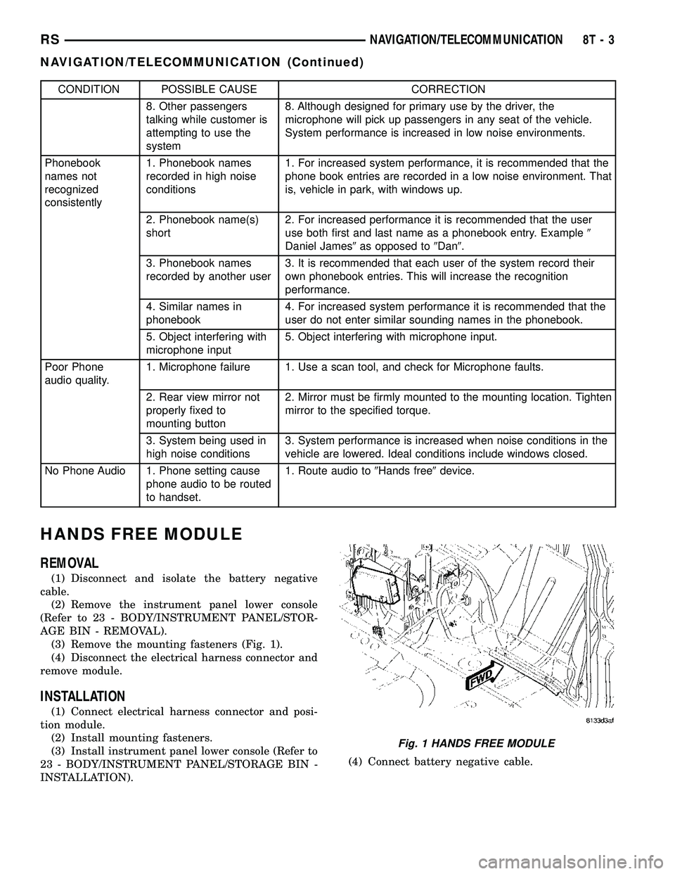
CONDITION POSSIBLE CAUSE CORRECTION
8. Other passengers
talking while customer is
attempting to use the
system8. Although designed for primary use by the driver, the
microphone will pick up passengers in any seat of the vehicle.
System performance is increased in low noise environments.
Phonebook
names not
recognized
consistently1. Phonebook names
recorded in high noise
conditions1. For increased system performance, it is recommended that the
phone book entries are recorded in a low noise environment. That
is, vehicle in park, with windows up.
2. Phonebook name(s)
short2. For increased performance it is recommended that the user
use both first and last name as a phonebook entry. Example9
Daniel James9as opposed to9Dan9.
3. Phonebook names
recorded by another user3. It is recommended that each user of the system record their
own phonebook entries. This will increase the recognition
performance.
4. Similar names in
phonebook4. For increased system performance it is recommended that the
user do not enter similar sounding names in the phonebook.
5. Object interfering with
microphone input5. Object interfering with microphone input.
Poor Phone
audio quality.1. Microphone failure 1. Use a scan tool, and check for Microphone faults.
2. Rear view mirror not
properly fixed to
mounting button2. Mirror must be firmly mounted to the mounting location. Tighten
mirror to the specified torque.
3. System being used in
high noise conditions3. System performance is increased when noise conditions in the
vehicle are lowered. Ideal conditions include windows closed.
No Phone Audio 1. Phone setting cause
phone audio to be routed
to handset.1. Route audio to9Hands free9device.
HANDS FREE MODULE
REMOVAL
(1) Disconnect and isolate the battery negative
cable.
(2) Remove the instrument panel lower console
(Refer to 23 - BODY/INSTRUMENT PANEL/STOR-
AGE BIN - REMOVAL).
(3) Remove the mounting fasteners (Fig. 1).
(4) Disconnect the electrical harness connector and
remove module.
INSTALLATION
(1) Connect electrical harness connector and posi-
tion module.
(2) Install mounting fasteners.
(3) Install instrument panel lower console (Refer to
23 - BODY/INSTRUMENT PANEL/STORAGE BIN -
INSTALLATION).(4) Connect battery negative cable.
Fig. 1 HANDS FREE MODULE
RSNAVIGATION/TELECOMMUNICATION8T-3
NAVIGATION/TELECOMMUNICATION (Continued)
Page 564 of 2339
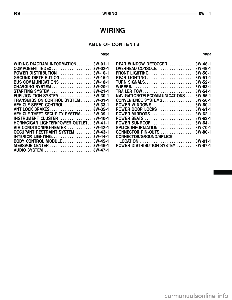
WIRING
TABLE OF CONTENTS
page page
WIRING DIAGRAM INFORMATION....... 8W-01-1
COMPONENT INDEX.................. 8W-02-1
POWER DISTRIBUTION............... 8W-10-1
GROUND DISTRIBUTION.............. 8W-15-1
BUS COMMUNICATIONS.............. 8W-18-1
CHARGING SYSTEM.................. 8W-20-1
STARTING SYSTEM.................. 8W-21-1
FUEL/IGNITION SYSTEM.............. 8W-30-1
TRANSMISSION CONTROL SYSTEM..... 8W-31-1
VEHICLE SPEED CONTROL............ 8W-33-1
ANTILOCK BRAKES................... 8W-35-1
VEHICLE THEFT SECURITY SYSTEM..... 8W-39-1
INSTRUMENT CLUSTER............... 8W-40-1
HORN/CIGAR LIGHTER/POWER OUTLET . . 8W-41-1
AIR CONDITIONING-HEATER........... 8W-42-1
OCCUPANT RESTRAINT SYSTEM........ 8W-43-1
INTERIOR LIGHTING.................. 8W-44-1
BODY CONTROL MODULE............. 8W-45-1
MESSAGE CENTER................... 8W-46-1
AUDIO SYSTEM..................... 8W-47-1REAR WINDOW DEFOGGER............ 8W-48-1
OVERHEAD CONSOLE................. 8W-49-1
FRONT LIGHTING.................... 8W-50-1
REAR LIGHTING..................... 8W-51-1
TURN SIGNALS...................... 8W-52-1
WIPERS............................ 8W-53-1
TRAILER TOW....................... 8W-54-1
NAVIGATION/TELECOMMUNICATIONS.... 8W-55-1
CONVENIENCE SYSTEMS.............. 8W-56-1
POWER WINDOWS................... 8W-60-1
POWER DOOR LOCKS................ 8W-61-1
POWER MIRRORS................... 8W-62-1
POWER SEATS...................... 8W-63-1
POWER SUNROOF................... 8W-64-1
SPLICE INFORMATION................ 8W-70-1
CONNECTOR PIN-OUTS............... 8W-80-1
CONNECTOR/GROUND/SPLICE
LOCATION........................ 8W-91-1
POWER DISTRIBUTION SYSTEM........ 8W-97-1 RSWIRING
8W-1
Page 582 of 2339
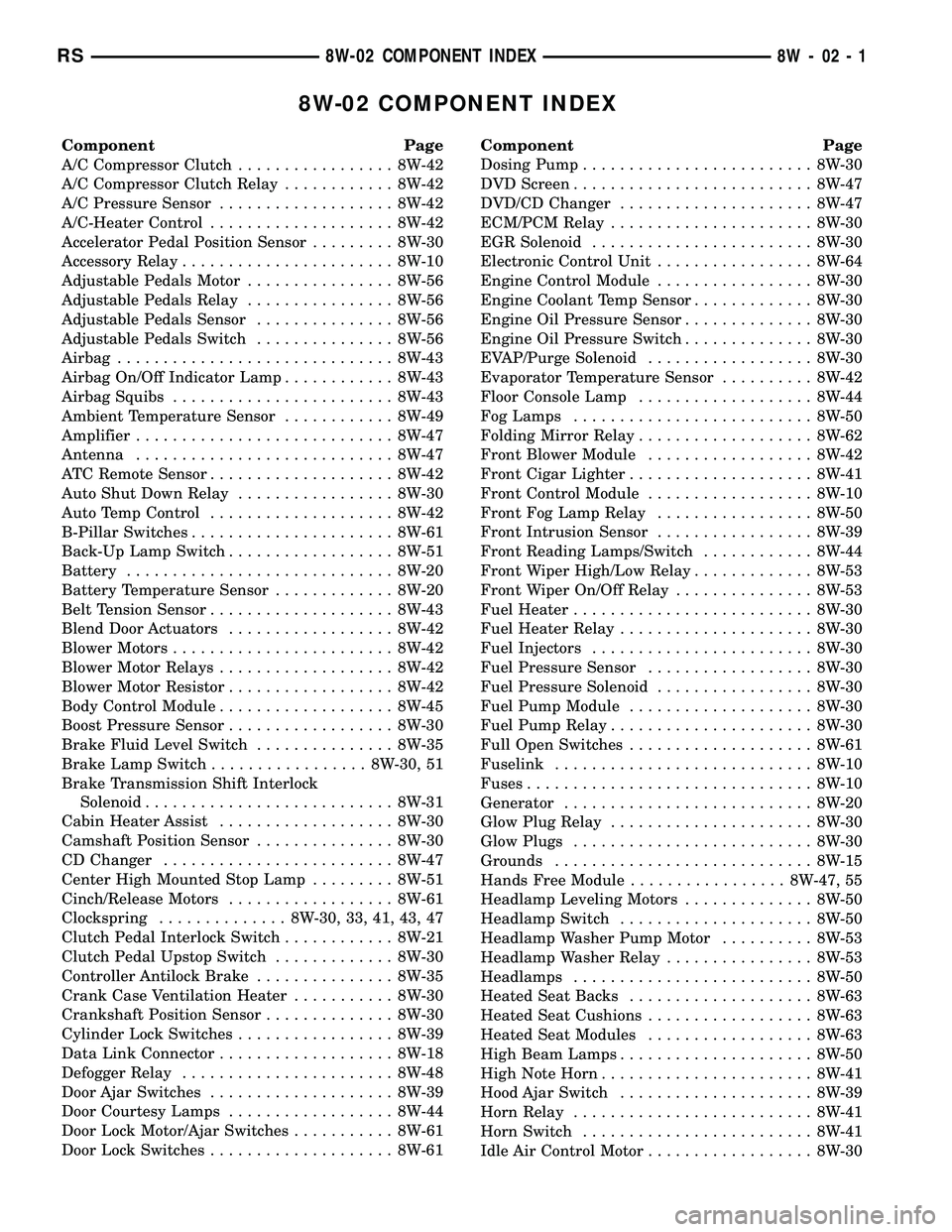
8W-02 COMPONENT INDEX
Component Page
A/C Compressor Clutch................. 8W-42
A/C Compressor Clutch Relay............ 8W-42
A/C Pressure Sensor................... 8W-42
A/C-Heater Control.................... 8W-42
Accelerator Pedal Position Sensor......... 8W-30
Accessory Relay....................... 8W-10
Adjustable Pedals Motor................ 8W-56
Adjustable Pedals Relay................ 8W-56
Adjustable Pedals Sensor............... 8W-56
Adjustable Pedals Switch............... 8W-56
Airbag.............................. 8W-43
Airbag On/Off Indicator Lamp............ 8W-43
Airbag Squibs........................ 8W-43
Ambient Temperature Sensor............ 8W-49
Amplifier............................ 8W-47
Antenna............................ 8W-47
ATC Remote Sensor.................... 8W-42
Auto Shut Down Relay................. 8W-30
Auto Temp Control.................... 8W-42
B-Pillar Switches...................... 8W-61
Back-Up Lamp Switch.................. 8W-51
Battery............................. 8W-20
Battery Temperature Sensor............. 8W-20
Belt Tension Sensor.................... 8W-43
Blend Door Actuators.................. 8W-42
Blower Motors........................ 8W-42
Blower Motor Relays................... 8W-42
Blower Motor Resistor.................. 8W-42
Body Control Module................... 8W-45
Boost Pressure Sensor.................. 8W-30
Brake Fluid Level Switch............... 8W-35
Brake Lamp Switch................. 8W-30, 51
Brake Transmission Shift Interlock
Solenoid........................... 8W-31
Cabin Heater Assist................... 8W-30
Camshaft Position Sensor............... 8W-30
CD Changer......................... 8W-47
Center High Mounted Stop Lamp......... 8W-51
Cinch/Release Motors.................. 8W-61
Clockspring.............. 8W-30, 33, 41, 43, 47
Clutch Pedal Interlock Switch............ 8W-21
Clutch Pedal Upstop Switch............. 8W-30
Controller Antilock Brake............... 8W-35
Crank Case Ventilation Heater........... 8W-30
Crankshaft Position Sensor.............. 8W-30
Cylinder Lock Switches................. 8W-39
Data Link Connector................... 8W-18
Defogger Relay....................... 8W-48
Door Ajar Switches.................... 8W-39
Door Courtesy Lamps.................. 8W-44
Door Lock Motor/Ajar Switches........... 8W-61
Door Lock Switches.................... 8W-61Component Page
Dosing Pump......................... 8W-30
DVD Screen.......................... 8W-47
DVD/CD Changer..................... 8W-47
ECM/PCM Relay...................... 8W-30
EGR Solenoid........................ 8W-30
Electronic Control Unit................. 8W-64
Engine Control Module................. 8W-30
Engine Coolant Temp Sensor............. 8W-30
Engine Oil Pressure Sensor.............. 8W-30
Engine Oil Pressure Switch.............. 8W-30
EVAP/Purge Solenoid.................. 8W-30
Evaporator Temperature Sensor.......... 8W-42
Floor Console Lamp................... 8W-44
Fog Lamps.......................... 8W-50
Folding Mirror Relay................... 8W-62
Front Blower Module.................. 8W-42
Front Cigar Lighter.................... 8W-41
Front Control Module.................. 8W-10
Front Fog Lamp Relay................. 8W-50
Front Intrusion Sensor................. 8W-39
Front Reading Lamps/Switch............ 8W-44
Front Wiper High/Low Relay............. 8W-53
Front Wiper On/Off Relay............... 8W-53
Fuel Heater.......................... 8W-30
Fuel Heater Relay..................... 8W-30
Fuel Injectors........................ 8W-30
Fuel Pressure Sensor.................. 8W-30
Fuel Pressure Solenoid................. 8W-30
Fuel Pump Module.................... 8W-30
Fuel Pump Relay...................... 8W-30
Full Open Switches.................... 8W-61
Fuselink............................ 8W-10
Fuses............................... 8W-10
Generator........................... 8W-20
Glow Plug Relay...................... 8W-30
Glow Plugs.......................... 8W-30
Grounds............................ 8W-15
Hands Free Module................. 8W-47, 55
Headlamp Leveling Motors.............. 8W-50
Headlamp Switch..................... 8W-50
Headlamp Washer Pump Motor.......... 8W-53
Headlamp Washer Relay................ 8W-53
Headlamps.......................... 8W-50
Heated Seat Backs.................... 8W-63
Heated Seat Cushions.................. 8W-63
Heated Seat Modules.................. 8W-63
High Beam Lamps..................... 8W-50
High Note Horn....................... 8W-41
Hood Ajar Switch..................... 8W-39
Horn Relay.......................... 8W-41
Horn Switch......................... 8W-41
Idle Air Control Motor.................. 8W-30
RS8W-02 COMPONENT INDEX8W-02-1
Page 583 of 2339
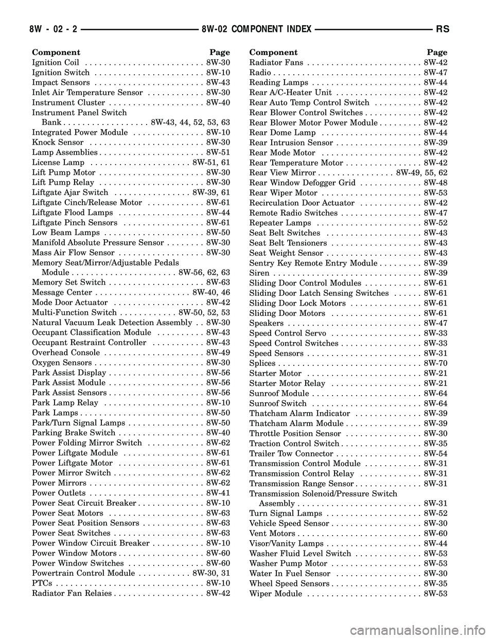
Component Page
Ignition Coil......................... 8W-30
Ignition Switch....................... 8W-10
Impact Sensors....................... 8W-43
Inlet Air Temperature Sensor............ 8W-30
Instrument Cluster.................... 8W-40
Instrument Panel Switch
Bank.................. 8W-43, 44, 52, 53, 63
Integrated Power Module............... 8W-10
Knock Sensor........................ 8W-30
Lamp Assemblies...................... 8W-51
License Lamp..................... 8W-51, 61
Lift Pump Motor...................... 8W-30
Lift Pump Relay...................... 8W-30
Liftgate Ajar Switch................ 8W-39, 61
Liftgate Cinch/Release Motor............ 8W-61
Liftgate Flood Lamps.................. 8W-44
Liftgate Pinch Sensors................. 8W-61
Low Beam Lamps..................... 8W-50
Manifold Absolute Pressure Sensor........ 8W-30
Mass Air Flow Sensor.................. 8W-30
Memory Seat/Mirror/Adjustable Pedals
Module...................... 8W-56, 62, 63
Memory Set Switch.................... 8W-63
Message Center.................... 8W-40, 46
Mode Door Actuator................... 8W-42
Multi-Function Switch............ 8W-50, 52, 53
Natural Vacuum Leak Detection Assembly . . 8W-30
Occupant Classification Module.......... 8W-43
Occupant Restraint Controller........... 8W-43
Overhead Console..................... 8W-49
Oxygen Sensors....................... 8W-30
Park Assist Display.................... 8W-56
Park Assist Module.................... 8W-56
Park Assist Sensors.................... 8W-56
Park Lamp Relay..................... 8W-10
Park Lamps.......................... 8W-50
Park/Turn Signal Lamps................ 8W-50
Parking Brake Switch.................. 8W-40
Power Folding Mirror Switch............ 8W-62
Power Liftgate Module................. 8W-61
Power Liftgate Motor.................. 8W-61
Power Mirror Switch................... 8W-62
Power Mirrors........................ 8W-62
Power Outlets........................ 8W-41
Power Seat Circuit Breaker.............. 8W-10
Power Seat Motors.................... 8W-63
Power Seat Position Sensors............. 8W-63
Power Seat Switches................... 8W-63
Power Window Circuit Breaker........... 8W-10
Power Window Motors.................. 8W-60
Power Window Switches................ 8W-60
Powertrain Control Module........... 8W-30, 31
PTCs............................... 8W-10
Radiator Fan Relaies................... 8W-42Component Page
Radiator Fans........................ 8W-42
Radio............................... 8W-47
Reading Lamps....................... 8W-44
Rear A/C-Heater Unit.................. 8W-42
Rear Auto Temp Control Switch.......... 8W-42
Rear Blower Control Switches............ 8W-42
Rear Blower Motor Power Module......... 8W-42
Rear Dome Lamp..................... 8W-44
Rear Intrusion Sensor.................. 8W-39
Rear Mode Motor..................... 8W-42
Rear Temperature Motor................ 8W-42
Rear View Mirror................ 8W-49, 55, 62
Rear Window Defogger Grid............. 8W-48
Rear Wiper Motor..................... 8W-53
Recirculation Door Actuator............. 8W-42
Remote Radio Switches................. 8W-47
Repeater Lamps...................... 8W-52
Seat Belt Switches.................... 8W-43
Seat Belt Tensioners................... 8W-43
Seat Weight Sensor.................... 8W-43
Sentry Key Remote Entry Module......... 8W-39
Siren............................... 8W-39
Sliding Door Control Modules............ 8W-61
Sliding Door Latch Sensing Switches...... 8W-61
Sliding Door Lock Motors............... 8W-61
Sliding Door Motors................... 8W-61
Speakers............................ 8W-47
Speed Control Servo................... 8W-33
Speed Control Switches................. 8W-33
Speed Sensors........................ 8W-31
Splices.............................. 8W-70
Starter Motor........................ 8W-21
Starter Motor Relay................... 8W-21
Sunroof Module....................... 8W-64
Sunroof Switch....................... 8W-64
Thatcham Alarm Indicator.............. 8W-39
Thatcham Alarm Module................ 8W-39
Throttle Position Sensor................ 8W-30
Traction Control Switch................. 8W-35
Trailer Tow Connector.................. 8W-54
Transmission Control Module............ 8W-31
Transmission Control Relay............. 8W-31
Transmission Range Sensor.............. 8W-31
Transmission Solenoid/Pressure Switch
Assembly.......................... 8W-31
Turn Signal Lamps.................... 8W-52
Vehicle Speed Sensor................... 8W-30
Vent Motors.......................... 8W-60
Visor/Vanity Lamps.................... 8W-44
Washer Fluid Level Switch.............. 8W-53
Washer Pump Motor................... 8W-53
Water In Fuel Sensor.................. 8W-30
Wheel Speed Sensors................... 8W-35
Wiper Module........................ 8W-53
8W - 02 - 2 8W-02 COMPONENT INDEXRS