torque CHRYSLER VOYAGER 2005 Service Manual
[x] Cancel search | Manufacturer: CHRYSLER, Model Year: 2005, Model line: VOYAGER, Model: CHRYSLER VOYAGER 2005Pages: 2339, PDF Size: 59.69 MB
Page 1952 of 2339
(5) Verify sunroof operation and alignment.
REAR HOUSING HOSE
(1) Connect the new drain hose to the sunroof
housing and test drainage (Fig. 1).
(2) Install headliner(Refer to 23 - BODY/INTERI-
OR/HEADLINER - INSTALLATION).
(3) Install sunroof opening trim lace.
(4) Connect the control switch wire connector and
install control switch.
(5) Verify sunroof operation and alignment.
GLASS PANEL
REMOVAL
(1) Move the glass panel to the vent position.
(2) Slide sunshade rearward to the open position.
(3) Remove the glass panel screws (Fig. 1).
(4) Lift off glass panel and remove from vehicle.
INSTALLATION
(1) Position glass panel on to mechanism lift arms.
(2) Start the attaching screws, and hand tighten
(Fig. 1).
(3) Adjust sunroof glass to fit flush with roof
line(Refer to 23 - BODY/SUNROOF/GLASS PANEL -
ADJUSTMENTS).
(4) Verify sunroof operation and alignment.
ADJUSTMENTS
SUNROOF GLASS PANEL ADJUSTMENT
(1) Move the sunshade rearward to the open posi-
tion.
(2) Move the sunroof glass panel to the fully closed
position.
(3) Loosen the forward attaching screws on each
side enough to make the front of the glass to adjust
up or down.
(4) Adjust the front surface of the sunroof glass
panel 0.00 mm to 1.75 mm (0.00 in. to 0.07 in.) below
the top surface of the roof.
(5) Tighten the front glass panel attaching screws
to 3.5 N´m (31 in. lbs.) torque (Fig. 1).
(6) Loosen the rear screws on each side enough to
make the rear adjustment (Fig. 1).
(7) Adjust the rear surface of the sunroof glass
panel 0.00 mm to 1.75 mm (0.03 in. to 0.07 in.) above
the top surface of the roof.
(8) Tighten the rear glass panel attaching screws
to 3.5 N´m (31 in. lbs.) torque (Fig. 1).
(9) Check for proper fit. If not OK, repeat glass
panel adjustment.
SUNROOF ASSEMBLY
REMOVAL
(1) Move glass panel to the fully closed position.
(2) Disconnect battery negative cable.
(3) Remove headliner (Refer to 23 - BODY/INTE-
RIOR/HEADLINER - REMOVAL).
(4) Disconnect the four drain tubes from sunroof
housing (Fig. 1).
(5) Loosen fasteners attaching sunroof assembly
(Fig. 1).
(6) With the aid of a helper, support the sunroof
and remove the fasteners attaching sunroof assembly
to roof panel (Fig. 1).
(7) Remove sunroof from vehicle.
INSTALLATION
(1) Raise sunroof module assembly and guide it
carefully into position.
(2) While supporting the sunroof assembly tighten
the attaching screws (Fig. 1). Tighten to 6 N´m (53
in. lbs.) torque.
(3) Connect the drain tubes to the sunroof (Fig. 1).
(4) Connect battery negative cable.
(5) Test sunroof operation, adjust as necessary(Re-
fer to 23 - BODY/SUNROOF/GLASS PANEL -
ADJUSTMENTS).
(6) Install headliner (Refer to 23 - BODY/INTERI-
OR/HEADLINER - INSTALLATION).
(7) Install sunroof opening trim lace position(Refer
to 23 - BODY/SUNROOF/OPENING TRIM LACE -
INSTALLATION).
SUNSHADE
REMOVAL
(1) Place the sunroof glass panel in the vent posi-
tion.
(2) Remove glass panel (Refer to 23 - BODY/SUN-
ROOF/GLASS PANEL - REMOVAL).
(3) Remove water channel (Fig. 1).
(4) Cycle sunroof motor to the open position.
(5) Move sunshade towards the closed position
stopping three to four inches from the closed position.
(6) Depress the spring feet clips on one side of the
sun shade.
(7) Remove sunshade.
INSTALLATION
(1) Place one side of the sunshade spring feet clips
into the top track U-frame.
(2) Depress the both releasing clips on the other
side to allow them to go into the top track U-frame.
(3) Move sunshade to the open position.
(4) Install water channel (Fig. 1).
RSSUNROOF23 - 173
DRAIN TUBE (Continued)
Page 2162 of 2339
TEMPERATURE CONTROL
If the heater outlet air temperature cannot be
adjusted with the temperature control knob on the
A/C-heater control panel, the following could require
service:
²Blend door binding.
²Faulty blend door actuator.
²Faulty A/C-heater control.
²Faulty related wiring harness or connectors.²Improper engine coolant temperature.
SPECIFICATIONS
A/C SYSTEM
The R-134a refrigerant system charge capacity for
this vehicle can be found on the underhood Specifica-
tion Label.
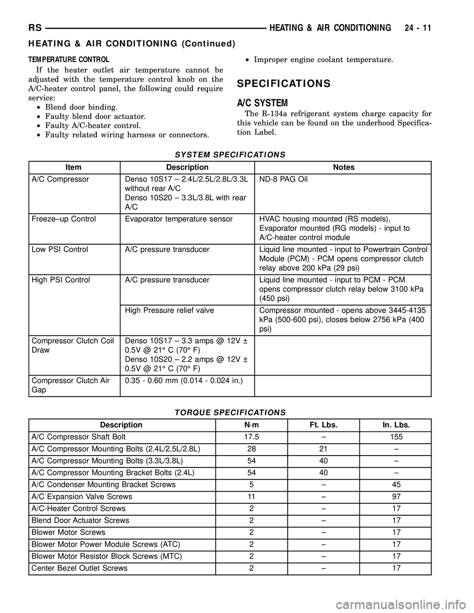
SYSTEM SPECIFICATIONS
Item Description Notes
A/C Compressor Denso 10S17 ± 2.4L/2.5L/2.8L/3.3L
without rear A/C
Denso 10S20 ± 3.3L/3.8L with rear
A/CND-8 PAG Oil
Freeze±up Control Evaporator temperature sensor HVAC housing mounted (RS models),
Evaporator mounted (RG models) - input to
A/C-heater control module
Low PSI Control A/C pressure transducer Liquid line mounted - input to Powertrain Control
Module (PCM) - PCM opens compressor clutch
relay above 200 kPa (29 psi)
High PSI Control A/C pressure transducer Liquid line mounted - input to PCM - PCM
opens compressor clutch relay below 3100 kPa
(450 psi)
High Pressure relief valve Compressor mounted - opens above 3445-4135
kPa (500-600 psi), closes below 2756 kPa (400
psi)
Compressor Clutch Coil
DrawDenso 10S17 ± 3.3 amps @ 12V
0.5V @ 21É C (70É F)
Denso 10S20 ± 2.2 amps @ 12V
0.5V @ 21É C (70É F)
Compressor Clutch Air
Gap0.35 - 0.60 mm (0.014 - 0.024 in.)
TORQUE SPECIFICATIONS
Description N´m Ft. Lbs. In. Lbs.
A/C Compressor Shaft Bolt 17.5 ± 155
A/C Compressor Mounting Bolts (2.4L/2.5L/2.8L) 28 21 ±
A/C Compressor Mounting Bolts (3.3L/3.8L) 54 40 ±
A/C Compressor Mounting Bracket Bolts (2.4L) 54 40 ±
A/C Condenser Mounting Bracket Screws 5 ± 45
A/C Expansion Valve Screws 11 ± 97
A/C-Heater Control Screws 2 ± 17
Blend Door Actuator Screws 2 ± 17
Blower Motor Screws 2 ± 17
Blower Motor Power Module Screws (ATC) 2 ± 17
Blower Motor Resistor Block Screws (MTC) 2 ± 17
Center Bezel Outlet Screws 2 ± 17
RSHEATING & AIR CONDITIONING24-11
HEATING & AIR CONDITIONING (Continued)
Page 2166 of 2339
(b) If the compressor clutch coil current reading
is four amperes or more, the coil is shorted and
must be replaced.
STANDARD PROCEDURE
CLUTCH INSPECTION
NOTE: The compressor clutch can be serviced in
the vehicle. The refrigerant system can remain fully-
charged during compressor clutch, pulley, or coil
replacement.
Examine the friction surfaces of the clutch pulley
and the clutch plate for wear. The pulley and plate
should be replaced if there is excessive wear or scor-
ing.
If the friction surfaces are oily, inspect the shaft
and nose area of the A/C compressor for refrigerant
oil. If refrigerant oil is found, the compressor shaft
seal is leaking and the A/C compressor must be
replaced.
Check the clutch pulley bearing for roughness or
excessive leakage of grease. Replace the pulley and
bearing assembly, if required.
A/C CLUTCH BREAK-IN
After a new A/C compressor clutch has been
installed, cycle the compressor clutch approximately
twenty times (five seconds on, then five seconds off).
During this procedure, set the A/C-heater controls to
the A/C Recirculation Mode, the blower motor in the
highest speed position, and the engine speed at 1500
to 2000 rpm. This procedure (burnishing) will seat
the opposing friction surfaces of the compressor
clutch, which provides optimum compressor clutch
torque capability.
REMOVAL
NOTE: The compressor clutch can be serviced in
the vehicle. The refrigerant system can remain fully-
charged during compressor clutch, pulley, or coil
replacement.
(1) Disconnect and isolate the negative battery
cable.
(2) Remove the accessory drive belt (Refer to 7 -
COOLING/ACCESSORY DRIVE/DRIVE BELTS -
REMOVAL).
(3) Raise and support the vehicle.
(4) Disconnect the engine wire harness connector
for the compressor clutch coil from the clutch coil pig-
tail wire connector on the top of the A/C compressor.
(5) On models with the 3.3L and 3.8L engines, dis-
engage the retainer on the engine wire harness com-pressor clutch coil take out from the bracket on the
top of the A/C compressor.
(6) On models with the 2.4L, 2.5L and 2.8L
engines, remove all of the compressor mounting bolts
except the upper left (rear of the A/C compressor),
which should only be loosened. Allow the front (pul-
ley end) of the A/C compressor to tilt downward far
enough to access the clutch for removal, then tighten
the loosened upper left compressor mounting bolt.
(7) On models with the 3.3L and 3.8L engines,
remove the two bolts and two nuts that secure the
A/C compressor to the engine. Disengage the mount-
ing ear at the front of the A/C compressor from the
stud on the engine, allow the front (pulley end) of the
A/C compressor to tilt downward far enough to access
the clutch for removal, then reinstall and tighten the
upper left compressor mounting bolt.
(8) Remove the compressor shaft bolt (Fig. 2). A
band-type oil filter wrench or a strap wrench may be
used to secure the clutch during bolt removal.
(9) Tap the clutch plate lightly with a plastic mal-
let to release it from the splines on the compressor
shaft. Remove the clutch plate and shim(s) from the
compressor shaft (Fig. 3).
NOTE: Use care not to lose any of the shim(s).
Fig. 2 A/C Compressor Shaft Bolt
1 - BOLT
2 - COMPRESSOR CLUTCH PLATE
RSCONTROLS - FRONT24-15
A/C COMPRESSOR CLUTCH/COIL (Continued)
Page 2275 of 2339
The following is a list of the monitored compo-
nents:
²Catalyst Monitor
²Comprehensive Components
²EGR (if equipped)
²Fuel Control (rich/lean)
²Oxygen Sensor Monitor
²Oxygen Sensor Heater Monitor
²Purge
²Misfire
²Natural Vacuum Leak Detection (NVLD)
COMPREHENSIVE COMPONENTS
Along with the major monitors, OBD II requires
that the diagnostic system monitor any component
that could affect emissions levels. In many cases,
these components were being tested under OBD I.
The OBD I requirements focused mainly on testing
emissions-related components for electrical opens and
shorts.
However, OBD II also requires that inputs from
powertrain components to the PCM be tested for
rationality, and that outputs to powertrain compo-
nents from the PCM be tested forfunctionality.
Methods for monitoring the various Comprehensive
Component monitoring include:
(1) Circuit Continuity
²Open
²Shorted high
²Shorted to ground
(2) Rationality or Proper Functioning
²Inputs tested for rationality
²Outputs tested for functionality
NOTE: Comprehensive component monitors are
continuous. Therefore, enabling conditions do not
apply. All will set a DTC and illuminate the MIL in 1-
trip.
Input RationalityÐWhile input signals to the
PCM are constantly being monitored for electrical
opens and shorts, they are also tested for rationality.
This means that the input signal is compared against
other inputs and information to see if it makes sense
under the current conditions.
PCM sensor inputs that are checked for rationality
include:
²Manifold Absolute Pressure (MAP) Sensor
²Oxygen Sensor (O2S) (slow response)
²Engine Coolant Temperature (ECT) Sensor
²Camshaft Position (CMP) Sensor
²Vehicle Speed Sensor
²Crankshaft Position (CKP) Sensor
²Intake Air Temperature (IAT) Sensor
²Throttle Position (TPS) Sensor
²Ambient/Battery Temperature Sensors
²Power Steering Switch²Oxygen Sensor Heater
²Engine Controller
²Brake Switch
²Natural Vacuum Leak Detection (NVLD)
²P/N Switch
²Trans Controls
Output FunctionalityÐPCM outputs are tested
for functionality in addition to testing for opens and
shorts. When the PCM provides a voltage to an out-
put component, it can verify that the command was
carried out by monitoring specific input signals for
expected changes. For example, when the PCM com-
mands the Idle Air Control (IAC) Motor to a specific
position under certain operating conditions, it expects
to see a specific (target) idle speed (RPM). If it does
not, it stores a DTC.
PCM outputs monitored for functionality include:
²Fuel Injectors
²Ignition Coils
²Torque Converter Clutch Solenoid
²Idle Air Control
²Purge Solenoid
²EGR Solenoid
²Radiator Fan Control
²Trans Controls
OXYGEN SENSOR (O2S) MONITOR
DESCRIPTIONÐEffective control of exhaust
emissions is achieved by an oxygen feedback system.
The most important element of the feedback system
is the O2S. The O2S is located in the exhaust path.
Once it reaches operating temperature 300É to 350ÉC
(572É to 662ÉF), the sensor generates a voltage that
is inversely proportional to the amount of oxygen in
the exhaust. When there is a large amount of oxygen
in the exhaust caused by a lean condition, misfire or
exhaust leak, the sensor produces a low voltage,
below 450 mV. When the oxygen content is lower,
caused by a rich condition, the sensor produces a
higher voltage, above 450mV.
The information obtained by the sensor is used to
calculate the fuel injector pulse width. The PCM is
programmed to maintain the optimum air/fuel ratio.
At this mixture ratio, the catalyst works best to
remove hydrocarbons (HC), carbon monoxide (CO)
and nitrous oxide (NOx) from the exhaust.
The O2S is also the main sensing element for the
EGR, Catalyst and Fuel Monitors, and purge.
The O2S may fail in any or all of the following
manners:
²Slow response rate (Big Slope)
²Reduced output voltage (Half Cycle)
²Heater Performance
Slow Response Rate (Big Slope)ÐResponse rate
is the time required for the sensor to switch from
lean to rich signal output once it is exposed to a
25 - 2 EMISSIONS CONTROLRS
EMISSIONS CONTROL (Continued)
Page 2280 of 2339
The information obtained by the sensor is used to
calculate the fuel injector pulse width. The PCM is
programmed to maintain the optimum air/fuel ratio.
At this mixture ratio, the catalyst works best to
remove hydrocarbons (HC), carbon monoxide (CO)
and nitrous oxide (NOx) from the exhaust.
The O2S is also the main sensing element for the
EGR (if equipped), Catalyst and Fuel Monitors.
The O2S may fail in any or all of the following
manners:
²Slow response rate
²Reduced output voltage
²Dynamic shift
²Shorted or open circuits
Response rate is the time required for the sensor to
switch from lean to rich once it is exposed to a richer
than optimum A/F mixture or vice versa. As the sen-
sor starts malfunctioning, it could take longer to
detect the changes in the oxygen content of the
exhaust gas.
The output voltage of the O2S ranges from 0 to 1
volt (voltages are offset by 2.5 volts on NGC vehi-
cles). A good sensor can easily generate any output
voltage in this range as it is exposed to different con-
centrations of oxygen. To detect a shift in the A/F
mixture (lean or rich), the output voltage has to
change beyond a threshold value. A malfunctioning
sensor could have difficulty changing beyond the
threshold value.
OXYGEN SENSOR HEATER MONITOR
If there is an oxygen sensor (O2S) DTC as well as
a O2S heater DTC, the O2S heater fault MUST be
repaired first. After the O2S fault is repaired, verify
that the heater circuit is operating correctly.
Effective control of exhaust emissions is achieved
by an oxygen feedback system. The most important
element of the feedback system is the O2S. The O2S
is located in the exhaust path. Once it reaches oper-
ating temperatures of 300É to 350ÉC (572 É to 662ÉF),
the sensor generates a voltage that is inversely pro-
portional to the amount of oxygen in the exhaust.
The information obtained by the sensor is used to
calculate the fuel injector pulse width. This main-
tains a 14.7 to 1 Air Fuel (A/F) ratio. At this mixture
ratio, the catalyst works best to remove hydrocarbons
(HC), carbon monoxide (CO) and nitrogen oxide
(NOx) from the exhaust.
The voltage readings taken from the O2S are very
temperature sensitive. The readings are not accurate
below 300ÉC. Heating of the O2S is done to allow the
engine controller to shift to closed loop control as
soon as possible. The heating element used to heat
the O2S must be tested to ensure that it is heating
the sensor properly.The O2S circuit is monitored for a drop in voltage.
The sensor output is used to test the heater by iso-
lating the effect of the heater element on the O2S
output voltage from the other effects.
EGR MONITOR (if equipped)
The Powertrain Control Module (PCM) performs
an on-board diagnostic check of the EGR system.
The EGR monitor is used to test whether the EGR
system is operating within specifications. The diag-
nostic check activates only during selected engine/
driving conditions. When the conditions are met, the
EGR is turned off (solenoid energized) and the O2S
compensation control is monitored. Turning off the
EGR shifts the air fuel (A/F) ratio in the lean direc-
tion. The O2S data should indicate an increase in the
O2 concentration in the combustion chamber when
the exhaust gases are no longer recirculated. While
this test does not directly measure the operation of
the EGR system, it can be inferred from the shift in
the O2S data whether the EGR system is operating
correctly. Because the O2S is being used, the O2S
test must pass its test before the EGR test. Also
looks at EGR linear potentiometer for feedback.
MISFIRE MONITOR
Excessive engine misfire results in increased cata-
lyst temperature and causes an increase in HC emis-
sions. Severe misfires could cause catalyst damage.
To prevent catalytic convertor damage, the PCM
monitors engine misfire.
The Powertrain Control Module (PCM) monitors
for misfire during most engine operating conditions
(positive torque) by looking at changes in the crank-
shaft speed. If a misfire occurs the speed of the
crankshaft will vary more than normal.
FUEL SYSTEM MONITOR
To comply with clean air regulations, vehicles are
equipped with catalytic converters. These converters
reduce the emission of hydrocarbons, oxides of nitro-
gen and carbon monoxide. The catalyst works best
when the air fuel (A/F) ratio is at or near the opti-
mum of 14.7 to 1.
The PCM is programmed to maintain the optimum
air/fuel ratio. This is done by making short term cor-
rections in the fuel injector pulse width based on the
O2S output. The programmed memory acts as a self
calibration tool that the engine controller uses to
compensate for variations in engine specifications,
sensor tolerances and engine fatigue over the life
span of the engine. By monitoring the actual air-fuel
ratio with the O2S (short term) and multiplying that
with the program long-term (adaptive) memory and
comparing that to the limit, it can be determined
whether it will pass an emissions test. If a malfunc-
RSEMISSIONS CONTROL25-7
EMISSIONS CONTROL (Continued)
Page 2284 of 2339
EVAPORATIVE EMISSIONS
TABLE OF CONTENTS
page page
EVAPORATIVE EMISSIONS
OPERATION - EVAPORATION CONTROL
SYSTEM............................11
SPECIFICATIONS
TORQUE............................12
EVAP/PURGE SOLENOID
DESCRIPTION.........................13
OPERATION...........................13
REMOVAL.............................13
INSTALLATION.........................13
FUEL FILLER CAP
DESCRIPTION.........................13
OPERATION...........................13
NATURAL VAC LEAK DETECTION ASSY
REMOVAL.............................14
INSTALLATION.........................14
LEAK DETECTION PUMP
REMOVAL.............................15
INSTALLATION.........................15
ORVR
OPERATION...........................15DIAGNOSIS AND TESTING - VEHICLE DOES
NOT FILL............................17
P C V VA LV E
DESCRIPTION.........................18
OPERATION...........................18
DIAGNOSIS AND TESTING - PCV SYSTEM . . . 18
VAPOR CANISTER
DESCRIPTION.........................19
OPERATION...........................19
REMOVAL
REMOVAL...........................19
REMOVAL - WITH NVLD - FOLD-IN-FLOOR . 20
REMOVAL - REAR EVAP CANISTER.......20
INSTALLATION
INSTALLATION.......................20
INSTALLATION - WITH NVLD - FOLD-IN-
FLOOR.............................20
INSTALLATION - REAR EVAP CANISTER . . . 21
EVAPORATIVE EMISSIONS
OPERATION - EVAPORATION CONTROL
SYSTEM
The evaporation control system prevents the emis-
sion of fuel tank vapors into the atmosphere. When
fuel evaporates in the fuel tank, the vapors pass
through vent hoses or tubes to an activated carbon
filled evaporative canister. The canister temporarily
holds the vapors. The Powertrain Control Module
(PCM) allows intake manifold vacuum to draw
vapors into the combustion chambers during certain
operating conditions (Fig. 1).All engines use a proportional purge solenoid sys-
tem. The PCM controls vapor flow by operating the
purge solenoid. Refer to Proportional Purge Solenoid
in this section.
NOTE: The evaporative system uses specially man-
ufactured hoses. If they need replacement, only use
fuel resistant hose. Also the hoses must be able to
pass an Ozone compliance test.
NOTE: For more information on Onboard Refueling
Vapor Recovery (ORVR), refer to the Fuel Delivery
section.
RSEVAPORATIVE EMISSIONS25-11
Page 2285 of 2339
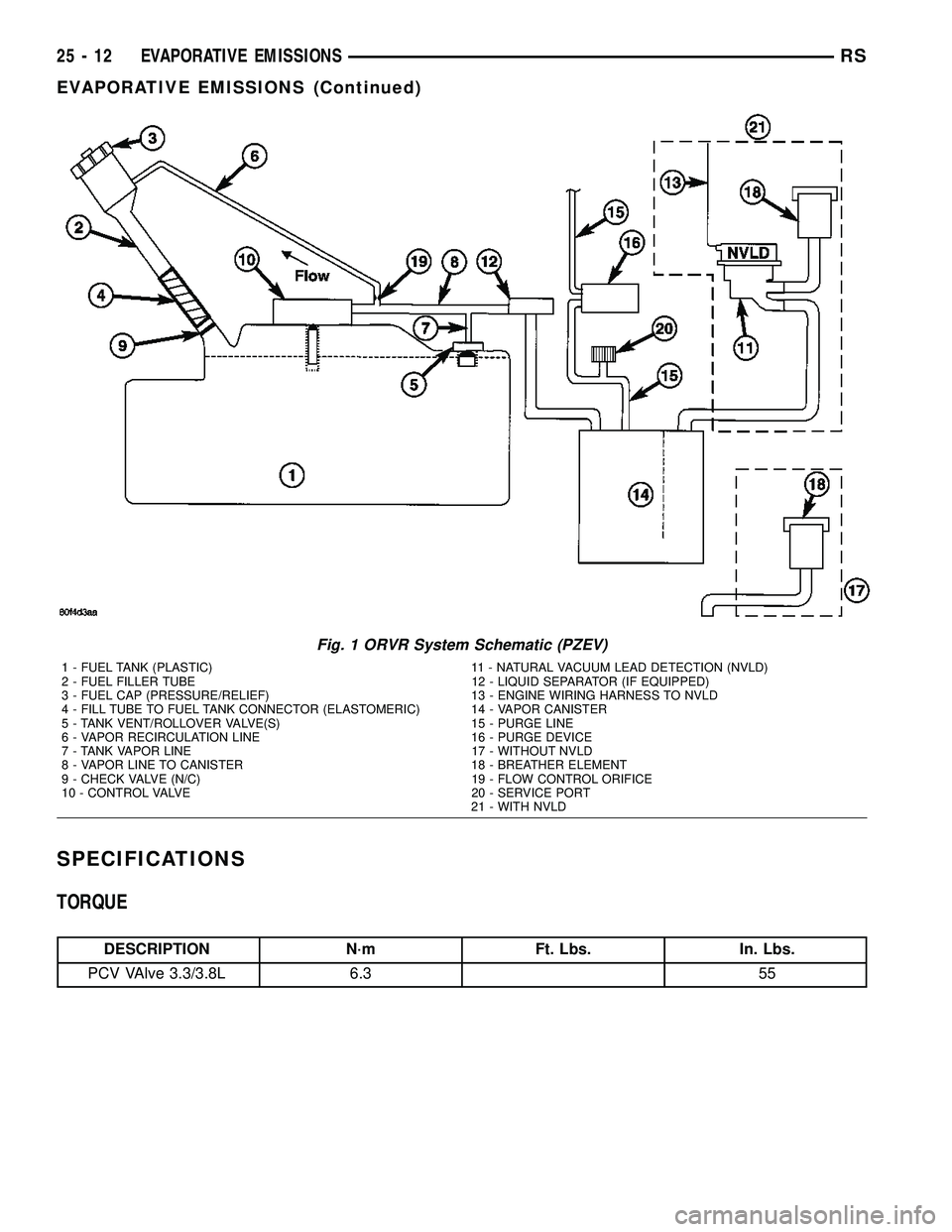
SPECIFICATIONS
TORQUE
DESCRIPTION N´m Ft. Lbs. In. Lbs.
PCV VAlve 3.3/3.8L 6.3 55
Fig. 1 ORVR System Schematic (PZEV)
1 - FUEL TANK (PLASTIC) 11 - NATURAL VACUUM LEAD DETECTION (NVLD)
2 - FUEL FILLER TUBE 12 - LIQUID SEPARATOR (IF EQUIPPED)
3 - FUEL CAP (PRESSURE/RELIEF) 13 - ENGINE WIRING HARNESS TO NVLD
4 - FILL TUBE TO FUEL TANK CONNECTOR (ELASTOMERIC) 14 - VAPOR CANISTER
5 - TANK VENT/ROLLOVER VALVE(S) 15 - PURGE LINE
6 - VAPOR RECIRCULATION LINE 16 - PURGE DEVICE
7 - TANK VAPOR LINE 17 - WITHOUT NVLD
8 - VAPOR LINE TO CANISTER 18 - BREATHER ELEMENT
9 - CHECK VALVE (N/C) 19 - FLOW CONTROL ORIFICE
10 - CONTROL VALVE 20 - SERVICE PORT
21 - WITH NVLD
25 - 12 EVAPORATIVE EMISSIONSRS
EVAPORATIVE EMISSIONS (Continued)
Page 2292 of 2339
(2) Install hose on PCV valve. Remove the
make-up air hose from the air plenum at the rear of
the engine. Hold a piece of stiff paper (parts tag)
loosely over the end of the make-up air hose.
(3) After allowing approximately one minute for
crankcase pressure to reduce, the paper should draw
up against the hose with noticeable force. If the
engine does not draw the paper against the grommet
after installing a new valve, replace the PCV valve
hose.
(4) Turn the engine off. Remove the PCV valve
from intake manifold. The valve should rattle when
shaken.
(5) Replace the PCV valve and retest the system if
it does not operate as described in the preceding
tests.Do not attempt to clean the old PCV valve.
If the valve rattles, apply a light coating of Loctitet
Pipe Sealant With Teflon to the threads. Thread the
PCV valve into the manifold plenum and tighten to 7
N´m (60 in. lbs.) torque.
VAPOR CANISTER
DESCRIPTION
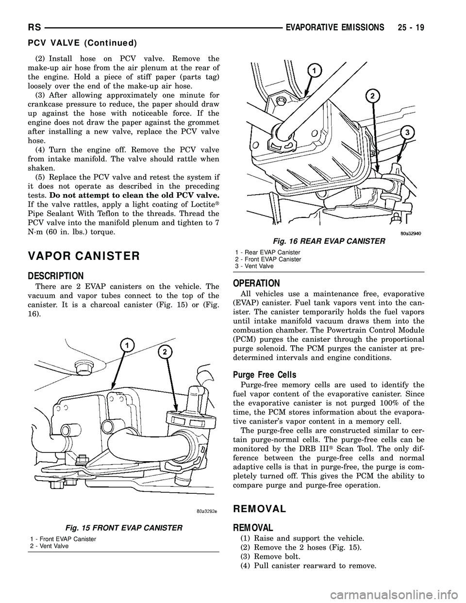
There are 2 EVAP canisters on the vehicle. The
vacuum and vapor tubes connect to the top of the
canister. It is a charcoal canister (Fig. 15) or (Fig.
16).OPERATION
All vehicles use a maintenance free, evaporative
(EVAP) canister. Fuel tank vapors vent into the can-
ister. The canister temporarily holds the fuel vapors
until intake manifold vacuum draws them into the
combustion chamber. The Powertrain Control Module
(PCM) purges the canister through the proportional
purge solenoid. The PCM purges the canister at pre-
determined intervals and engine conditions.
Purge Free Cells
Purge-free memory cells are used to identify the
fuel vapor content of the evaporative canister. Since
the evaporative canister is not purged 100% of the
time, the PCM stores information about the evapora-
tive canister's vapor content in a memory cell.
The purge-free cells are constructed similar to cer-
tain purge-normal cells. The purge-free cells can be
monitored by the DRB IIItScan Tool. The only dif-
ference between the purge-free cells and normal
adaptive cells is that in purge-free, the purge is com-
pletely turned off. This gives the PCM the ability to
compare purge and purge-free operation.
REMOVAL
REMOVAL
(1) Raise and support the vehicle.
(2) Remove the 2 hoses (Fig. 15).
(3) Remove bolt.
(4) Pull canister rearward to remove.
Fig. 15 FRONT EVAP CANISTER
1 - Front EVAP Canister
2 - Vent Valve
Fig. 16 REAR EVAP CANISTER
1 - Rear EVAP Canister
2 - Front EVAP Canister
3 - Vent Valve
RSEVAPORATIVE EMISSIONS25-19
PCV VALVE (Continued)
Page 2295 of 2339
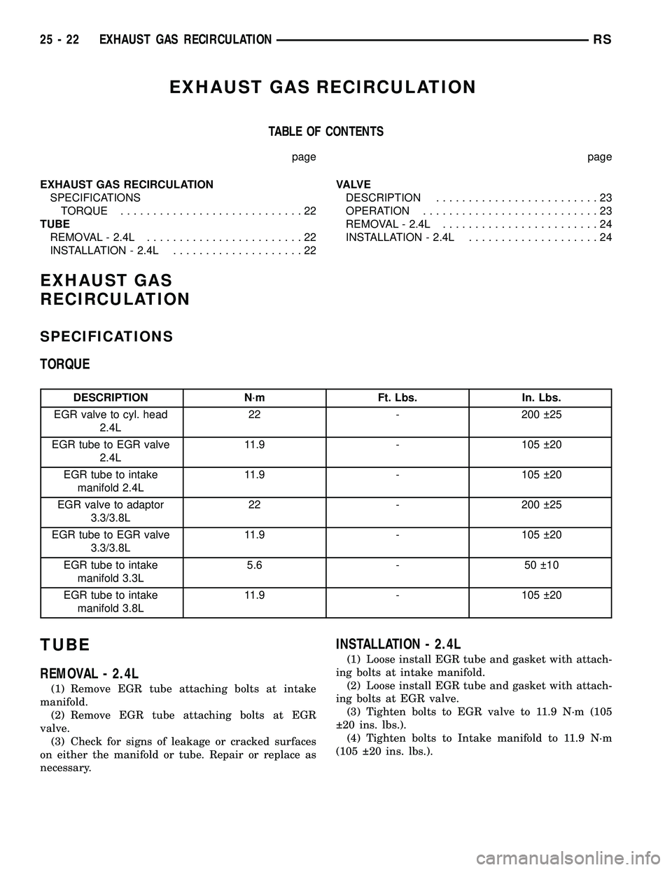
EXHAUST GAS RECIRCULATION
TABLE OF CONTENTS
page page
EXHAUST GAS RECIRCULATION
SPECIFICATIONS
TORQUE............................22
TUBE
REMOVAL - 2.4L........................22
INSTALLATION - 2.4L....................22VA LV E
DESCRIPTION.........................23
OPERATION...........................23
REMOVAL - 2.4L........................24
INSTALLATION - 2.4L....................24
EXHAUST GAS
RECIRCULATION
SPECIFICATIONS
TORQUE
DESCRIPTION N´m Ft. Lbs. In. Lbs.
EGR valve to cyl. head
2.4L22 - 200 25
EGR tube to EGR valve
2.4L11.9 - 105 20
EGR tube to intake
manifold 2.4L11.9 - 105 20
EGR valve to adaptor
3.3/3.8L22 - 200 25
EGR tube to EGR valve
3.3/3.8L11.9 - 105 20
EGR tube to intake
manifold 3.3L5.6 - 50 10
EGR tube to intake
manifold 3.8L11.9 - 105 20
TUBE
REMOVAL - 2.4L
(1) Remove EGR tube attaching bolts at intake
manifold.
(2) Remove EGR tube attaching bolts at EGR
valve.
(3) Check for signs of leakage or cracked surfaces
on either the manifold or tube. Repair or replace as
necessary.
INSTALLATION - 2.4L
(1) Loose install EGR tube and gasket with attach-
ing bolts at intake manifold.
(2) Loose install EGR tube and gasket with attach-
ing bolts at EGR valve.
(3) Tighten bolts to EGR valve to 11.9 N´m (105
20 ins. lbs.).
(4) Tighten bolts to Intake manifold to 11.9 N´m
(105 20 ins. lbs.).
25 - 22 EXHAUST GAS RECIRCULATIONRS
Page 2297 of 2339
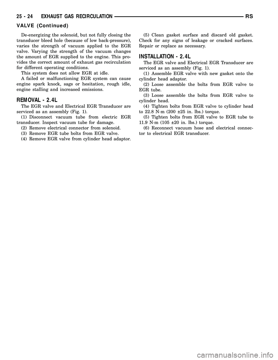
De-energizing the solenoid, but not fully closing the
transducer bleed hole (because of low back-pressure),
varies the strength of vacuum applied to the EGR
valve. Varying the strength of the vacuum changes
the amount of EGR supplied to the engine. This pro-
vides the correct amount of exhaust gas recirculation
for different operating conditions.
This system does not allow EGR at idle.
A failed or malfunctioning EGR system can cause
engine spark knock, sags or hesitation, rough idle,
engine stalling and increased emissions.
REMOVAL - 2.4L
The EGR valve and Electrical EGR Transducer are
serviced as an assembly (Fig. 1).
(1) Disconnect vacuum tube from electric EGR
transducer. Inspect vacuum tube for damage.
(2) Remove electrical connector from solenoid.
(3) Remove EGR tube bolts from EGR valve.
(4) Remove EGR valve from cylinder head adaptor.(5) Clean gasket surface and discard old gasket.
Check for any signs of leakage or cracked surfaces.
Repair or replace as necessary.
INSTALLATION - 2.4L
The EGR valve and Electrical EGR Transducer are
serviced as an assembly (Fig. 1).
(1) Assemble EGR valve with new gasket onto the
cylinder head adaptor.
(2) Loose assemble the bolts from EGR valve to
EGR tube.
(3) Loose assemble the bolts from EGR valve to
cylinder head.
(4) Tighten bolts from EGR valve to cylinder head
to 22.8 N´m (200 25 in. lbs.) torque.
(5) Tighten bolts from EGR valve to EGR tube to
11.9 N´m (105 20 in. lbs.) torque.
(6) Reconnect vacuum hose and electrical connec-
tor to electrical EGR transducer.
25 - 24 EXHAUST GAS RECIRCULATIONRS
VALVE (Continued)