torque CHRYSLER VOYAGER 2005 Owner's Guide
[x] Cancel search | Manufacturer: CHRYSLER, Model Year: 2005, Model line: VOYAGER, Model: CHRYSLER VOYAGER 2005Pages: 2339, PDF Size: 59.69 MB
Page 86 of 2339
(2) Remove the bolts securing the stabilizer bar to
links on each end of the bar.
(3) While holding the stabilizer bar in place,
remove the bolts that attach the stabilizer bar bush-
ing retainers to the rear axle.
(4) Remove the stabilizer bar from the vehicle.
(5) If the links need to be serviced, remove the
upper link arm to bracket bolt. Then remove link
arm from frame rail attaching bracket.
REMOVAL - FWD
(1) Raise vehicle. See Hoisting in Lubrication and
Maintenance.
(2) Remove the bolts securing the stabilizer bar to
links on each side of bar.
(3) While holding the stabilizer bar in place,
remove the bolts that attach the stabilizer bar bush-
ing retainers to the rear axle.
(4) Remove the stabilizer bar from the vehicle.
REMOVAL - FWD - FOLD-IN-FLOOR SEATING
(1) Raise and support vehicle. (Refer to LUBRICA-
TION & MAINTENANCE/HOISTING - STANDARD
PROCEDURE)
(2) At each end of the stabilizer bar, remove the
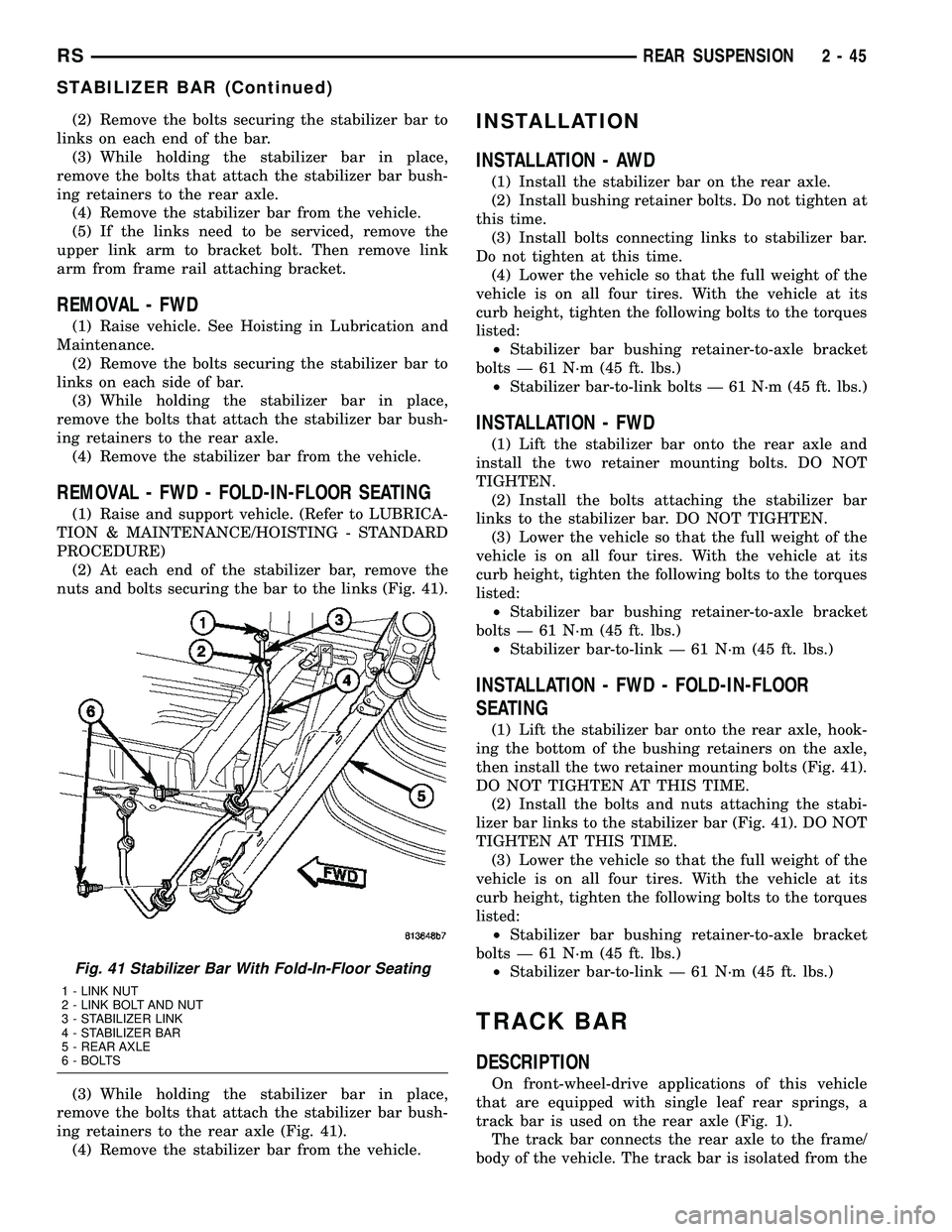
nuts and bolts securing the bar to the links (Fig. 41).
(3) While holding the stabilizer bar in place,
remove the bolts that attach the stabilizer bar bush-
ing retainers to the rear axle (Fig. 41).
(4) Remove the stabilizer bar from the vehicle.
INSTALLATION
INSTALLATION - AWD
(1) Install the stabilizer bar on the rear axle.
(2) Install bushing retainer bolts. Do not tighten at
this time.
(3) Install bolts connecting links to stabilizer bar.
Do not tighten at this time.
(4) Lower the vehicle so that the full weight of the
vehicle is on all four tires. With the vehicle at its
curb height, tighten the following bolts to the torques
listed:
²Stabilizer bar bushing retainer-to-axle bracket
bolts Ð 61 N´m (45 ft. lbs.)
²Stabilizer bar-to-link bolts Ð 61 N´m (45 ft. lbs.)
INSTALLATION - FWD
(1) Lift the stabilizer bar onto the rear axle and
install the two retainer mounting bolts. DO NOT
TIGHTEN.
(2) Install the bolts attaching the stabilizer bar
links to the stabilizer bar. DO NOT TIGHTEN.
(3) Lower the vehicle so that the full weight of the
vehicle is on all four tires. With the vehicle at its
curb height, tighten the following bolts to the torques
listed:
²Stabilizer bar bushing retainer-to-axle bracket
bolts Ð 61 N´m (45 ft. lbs.)
²Stabilizer bar-to-link Ð 61 N´m (45 ft. lbs.)
INSTALLATION - FWD - FOLD-IN-FLOOR
SEATING
(1) Lift the stabilizer bar onto the rear axle, hook-
ing the bottom of the bushing retainers on the axle,
then install the two retainer mounting bolts (Fig. 41).
DO NOT TIGHTEN AT THIS TIME.
(2) Install the bolts and nuts attaching the stabi-
lizer bar links to the stabilizer bar (Fig. 41). DO NOT
TIGHTEN AT THIS TIME.
(3) Lower the vehicle so that the full weight of the
vehicle is on all four tires. With the vehicle at its
curb height, tighten the following bolts to the torques
listed:
²Stabilizer bar bushing retainer-to-axle bracket
bolts Ð 61 N´m (45 ft. lbs.)
²Stabilizer bar-to-link Ð 61 N´m (45 ft. lbs.)
TRACK BAR
DESCRIPTION
On front-wheel-drive applications of this vehicle
that are equipped with single leaf rear springs, a
track bar is used on the rear axle (Fig. 1).
The track bar connects the rear axle to the frame/
body of the vehicle. The track bar is isolated from the
Fig. 41 Stabilizer Bar With Fold-In-Floor Seating
1 - LINK NUT
2 - LINK BOLT AND NUT
3 - STABILIZER LINK
4 - STABILIZER BAR
5 - REAR AXLE
6 - BOLTS
RSREAR SUSPENSION2-45
STABILIZER BAR (Continued)
Page 87 of 2339
body of the vehicle by an isolator bushing located in
each end of the track bar.
OPERATION
The track bar prevents excessive side-to-side move-
ment of the rear axle. The track bar is used to keep
the location of the axle in the correct position for
optimum handling and control of the vehicle.
REMOVAL
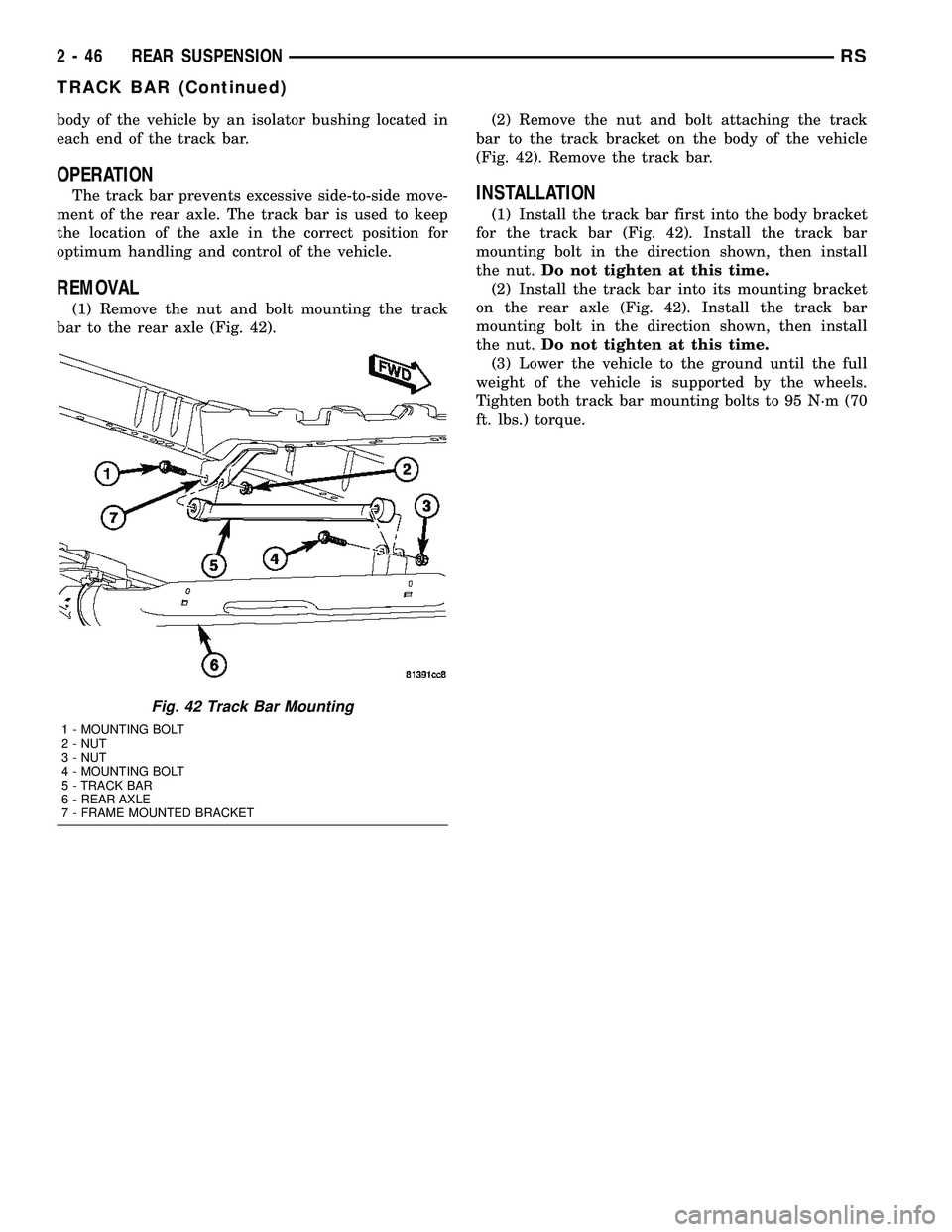
(1) Remove the nut and bolt mounting the track
bar to the rear axle (Fig. 42).(2) Remove the nut and bolt attaching the track
bar to the track bracket on the body of the vehicle
(Fig. 42). Remove the track bar.
INSTALLATION
(1) Install the track bar first into the body bracket
for the track bar (Fig. 42). Install the track bar
mounting bolt in the direction shown, then install
the nut.Do not tighten at this time.
(2) Install the track bar into its mounting bracket
on the rear axle (Fig. 42). Install the track bar
mounting bolt in the direction shown, then install
the nut.Do not tighten at this time.
(3) Lower the vehicle to the ground until the full
weight of the vehicle is supported by the wheels.
Tighten both track bar mounting bolts to 95 N´m (70
ft. lbs.) torque.
Fig. 42 Track Bar Mounting
1 - MOUNTING BOLT
2 - NUT
3 - NUT
4 - MOUNTING BOLT
5 - TRACK BAR
6 - REAR AXLE
7 - FRAME MOUNTED BRACKET
2 - 46 REAR SUSPENSIONRS
TRACK BAR (Continued)
Page 91 of 2339
THRUST ANGLE
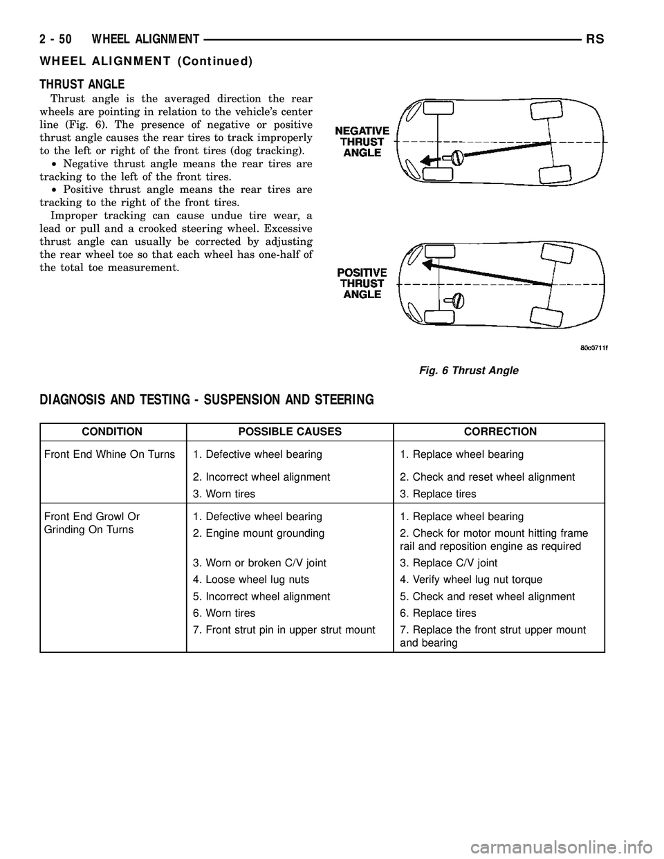
Thrust angle is the averaged direction the rear
wheels are pointing in relation to the vehicle's center
line (Fig. 6). The presence of negative or positive
thrust angle causes the rear tires to track improperly
to the left or right of the front tires (dog tracking).
²Negative thrust angle means the rear tires are
tracking to the left of the front tires.
²Positive thrust angle means the rear tires are
tracking to the right of the front tires.
Improper tracking can cause undue tire wear, a
lead or pull and a crooked steering wheel. Excessive
thrust angle can usually be corrected by adjusting
the rear wheel toe so that each wheel has one-half of
the total toe measurement.
DIAGNOSIS AND TESTING - SUSPENSION AND STEERING
CONDITION POSSIBLE CAUSES CORRECTION
Front End Whine On Turns 1. Defective wheel bearing 1. Replace wheel bearing
2. Incorrect wheel alignment 2. Check and reset wheel alignment
3. Worn tires 3. Replace tires
Front End Growl Or
Grinding On Turns1. Defective wheel bearing 1. Replace wheel bearing
2. Engine mount grounding 2. Check for motor mount hitting frame
rail and reposition engine as required
3. Worn or broken C/V joint 3. Replace C/V joint
4. Loose wheel lug nuts 4. Verify wheel lug nut torque
5. Incorrect wheel alignment 5. Check and reset wheel alignment
6. Worn tires 6. Replace tires
7. Front strut pin in upper strut mount 7. Replace the front strut upper mount
and bearing
Fig. 6 Thrust Angle
2 - 50 WHEEL ALIGNMENTRS
WHEEL ALIGNMENT (Continued)
Page 92 of 2339
CONDITION POSSIBLE CAUSES CORRECTION
Front End Clunk Or Snap
On Turns1. Loose lug nuts 1. Verify wheel lug nut torque
2. Worn or broken C/V joint 2. Replace C/V joint
3. Worn or loose tie rod 3. Tighten or replace tie rod end
4. Worn or loose ball joint 4. Tighten or replace ball joint
5. Worn/loose control arm bushing 5. Replace control arm bushing
6. Loose stabilizer bar. 6. Tighten stabilizer bar to specified
torque
7. Loose strut mount to body
attachment7. Tighten strut attachment to specified
torque
8. Loose crossmember bolts 8. Tighten crossmember bolts to
specified torque
Front End Whine With
Vehicle Going Straight At A
Constant Speed1. Defective wheel bearing 1. Replace wheel bearing
2. Incorrect wheel alignment 2. Check and reset wheel alignment
3. Worn tires 3. Replace tires
4. Worn or defective transaxle gears or
bearings4. Replace transaxle gears or bearings
Front End Growl Or
Grinding With Vehicle
Going Straight At A
Constant Speed1. Engine mount grounding 1. Reposition engine as required
2. Worn or broken C/V joint 2. Replace C/V joint
Front End Whine When
Accelerating Or
Decelerating1. Worn or defective transaxle gears or
bearings1. Replace transaxle gears or bearings
Front End Clunk When
Accelerating Or
Decelerating1. Worn or broken engine mount 1. Replace engine mount
2. Worn or defective transaxle gears or
bearings2. Replace transaxle gears or bearings
3. Loose lug nuts 3. Verify wheel lug nut torque
4. Worn or broken C/V joint 4. Replace C/V joint
5. Worn or loose ball joint 5. Tighten or replace ball joint
6. Worn or loose control arm bushing 6. Replace control arm bushing
7. Loose crossmember bolts 7. Tighten crossmember bolts to
specified torque
8. Worn tie rod end 8. Replace tie rod end
Road Wander 1. Incorrect tire pressure 1. Inflate tires to recommended pressure
2. Incorrect front or rear wheel toe 2. Check and reset wheel toe
3. Worn wheel bearings 3. Replace wheel bearing
4. Worn control arm bushings 4. Replace control arm bushing
5. Excessive friction in steering gear 5. Replace steering gear
6. Excessive friction in steering shaft
coupling6. Replace steering coupler
7. Excessive friction in strut upper
bearing7. Replace strut bearing
RSWHEEL ALIGNMENT2-51
WHEEL ALIGNMENT (Continued)
Page 93 of 2339
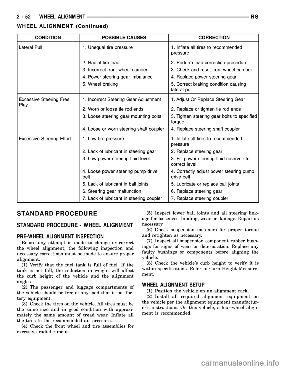
CONDITION POSSIBLE CAUSES CORRECTION
Lateral Pull 1. Unequal tire pressure 1. Inflate all tires to recommended
pressure
2. Radial tire lead 2. Perform lead correction procedure
3. Incorrect front wheel camber 3. Check and reset front wheel camber
4. Power steering gear imbalance 4. Replace power steering gear
5. Wheel braking 5. Correct braking condition causing
lateral pull
Excessive Steering Free
Play1. Incorrect Steering Gear Adjustment 1. Adjust Or Replace Steering Gear
2. Worn or loose tie rod ends 2. Replace or tighten tie rod ends
3. Loose steering gear mounting bolts 3. Tighten steering gear bolts to specified
torque
4. Loose or worn steering shaft coupler 4. Replace steering shaft coupler
Excessive Steering Effort 1. Low tire pressure 1. Inflate all tires to recommended
pressure
2. Lack of lubricant in steering gear 2. Replace steering gear
3. Low power steering fluid level 3. Fill power steering fluid reservoir to
correct level
4. Loose power steering pump drive
belt4. Correctly adjust power steering pump
drive belt
5. Lack of lubricant in ball joints 5. Lubricate or replace ball joints
6. Steering gear malfunction 6. Replace steering gear
7. Lack of lubricant in steering coupler 7. Replace steering coupler
STANDARD PROCEDURE
STANDARD PROCEDURE - WHEEL ALIGNMENT
PRE-WHEEL ALIGNMENT INSPECTION
Before any attempt is made to change or correct
the wheel alignment, the following inspection and
necessary corrections must be made to ensure proper
alignment.
(1) Verify that the fuel tank is full of fuel. If the
tank is not full, the reduction in weight will affect
the curb height of the vehicle and the alignment
angles.
(2) The passenger and luggage compartments of
the vehicle should be free of any load that is not fac-
tory equipment.
(3) Check the tires on the vehicle. All tires must be
the same size and in good condition with approxi-
mately the same amount of tread wear. Inflate all
the tires to the recommended air pressure.
(4) Check the front wheel and tire assemblies for
excessive radial runout.(5) Inspect lower ball joints and all steering link-
age for looseness, binding, wear or damage. Repair as
necessary.
(6) Check suspension fasteners for proper torque
and retighten as necessary.
(7) Inspect all suspension component rubber bush-
ings for signs of wear or deterioration. Replace any
faulty bushings or components before aligning the
vehicle.
(8) Check the vehicle's curb height to verify it is
within specifications. Refer to Curb Height Measure-
ment.
WHEEL ALIGNMENT SETUP
(1) Position the vehicle on an alignment rack.
(2) Install all required alignment equipment on
the vehicle per the alignment equipment manufactur-
er's instructions. On this vehicle, a four-wheel align-
ment is recommended.
2 - 52 WHEEL ALIGNMENTRS
WHEEL ALIGNMENT (Continued)
Page 95 of 2339
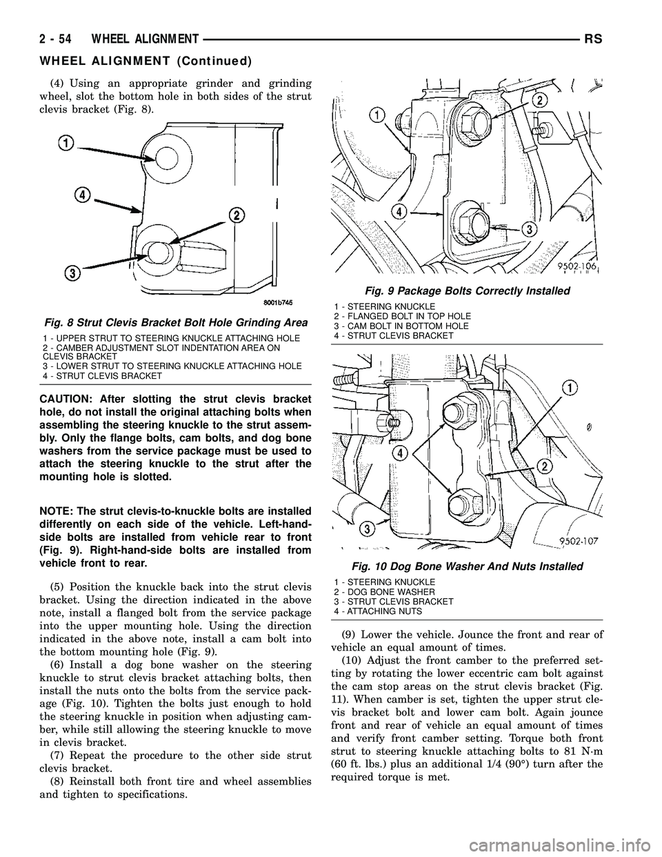
(4) Using an appropriate grinder and grinding
wheel, slot the bottom hole in both sides of the strut
clevis bracket (Fig. 8).
CAUTION: After slotting the strut clevis bracket
hole, do not install the original attaching bolts when
assembling the steering knuckle to the strut assem-
bly. Only the flange bolts, cam bolts, and dog bone
washers from the service package must be used to
attach the steering knuckle to the strut after the
mounting hole is slotted.
NOTE: The strut clevis-to-knuckle bolts are installed
differently on each side of the vehicle. Left-hand-
side bolts are installed from vehicle rear to front
(Fig. 9). Right-hand-side bolts are installed from
vehicle front to rear.
(5) Position the knuckle back into the strut clevis
bracket. Using the direction indicated in the above
note, install a flanged bolt from the service package
into the upper mounting hole. Using the direction
indicated in the above note, install a cam bolt into
the bottom mounting hole (Fig. 9).
(6) Install a dog bone washer on the steering
knuckle to strut clevis bracket attaching bolts, then
install the nuts onto the bolts from the service pack-
age (Fig. 10). Tighten the bolts just enough to hold
the steering knuckle in position when adjusting cam-
ber, while still allowing the steering knuckle to move
in clevis bracket.
(7) Repeat the procedure to the other side strut
clevis bracket.
(8) Reinstall both front tire and wheel assemblies
and tighten to specifications.(9) Lower the vehicle. Jounce the front and rear of
vehicle an equal amount of times.
(10) Adjust the front camber to the preferred set-
ting by rotating the lower eccentric cam bolt against
the cam stop areas on the strut clevis bracket (Fig.
11). When camber is set, tighten the upper strut cle-
vis bracket bolt and lower cam bolt. Again jounce
front and rear of vehicle an equal amount of times
and verify front camber setting. Torque both front
strut to steering knuckle attaching bolts to 81 N´m
(60 ft. lbs.) plus an additional 1/4 (90É) turn after the
required torque is met.
Fig. 8 Strut Clevis Bracket Bolt Hole Grinding Area
1 - UPPER STRUT TO STEERING KNUCKLE ATTACHING HOLE
2 - CAMBER ADJUSTMENT SLOT INDENTATION AREA ON
CLEVIS BRACKET
3 - LOWER STRUT TO STEERING KNUCKLE ATTACHING HOLE
4 - STRUT CLEVIS BRACKET
Fig. 9 Package Bolts Correctly Installed
1 - STEERING KNUCKLE
2 - FLANGED BOLT IN TOP HOLE
3 - CAM BOLT IN BOTTOM HOLE
4 - STRUT CLEVIS BRACKET
Fig. 10 Dog Bone Washer And Nuts Installed
1 - STEERING KNUCKLE
2 - DOG BONE WASHER
3 - STRUT CLEVIS BRACKET
4 - ATTACHING NUTS
2 - 54 WHEEL ALIGNMENTRS
WHEEL ALIGNMENT (Continued)
Page 96 of 2339
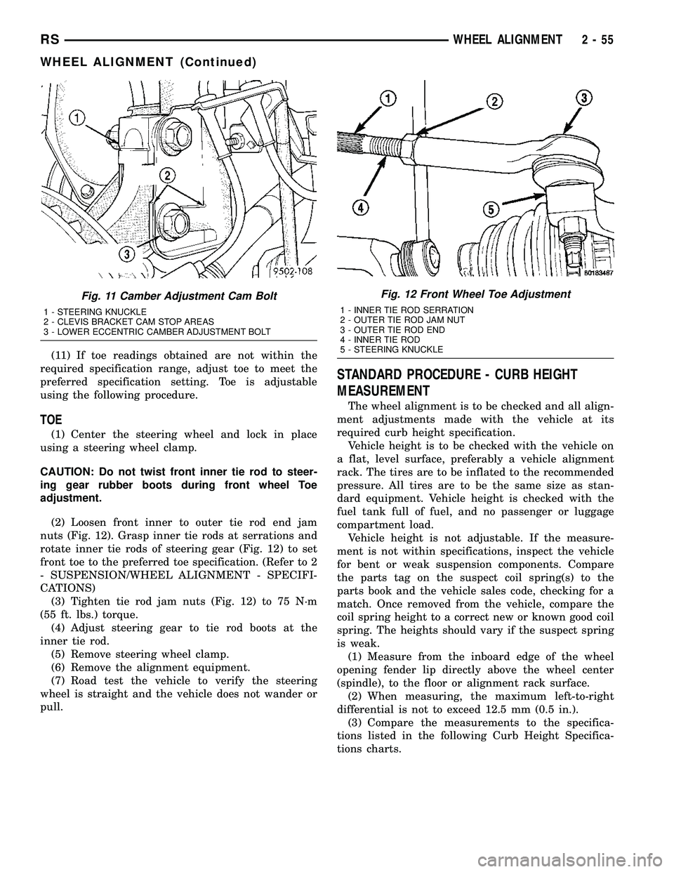
(11) If toe readings obtained are not within the
required specification range, adjust toe to meet the
preferred specification setting. Toe is adjustable
using the following procedure.
TOE
(1) Center the steering wheel and lock in place
using a steering wheel clamp.
CAUTION: Do not twist front inner tie rod to steer-
ing gear rubber boots during front wheel Toe
adjustment.
(2) Loosen front inner to outer tie rod end jam
nuts (Fig. 12). Grasp inner tie rods at serrations and
rotate inner tie rods of steering gear (Fig. 12) to set
front toe to the preferred toe specification. (Refer to 2
- SUSPENSION/WHEEL ALIGNMENT - SPECIFI-
CATIONS)
(3) Tighten tie rod jam nuts (Fig. 12) to 75 N´m
(55 ft. lbs.) torque.
(4) Adjust steering gear to tie rod boots at the
inner tie rod.
(5) Remove steering wheel clamp.
(6) Remove the alignment equipment.
(7) Road test the vehicle to verify the steering
wheel is straight and the vehicle does not wander or
pull.
STANDARD PROCEDURE - CURB HEIGHT
MEASUREMENT
The wheel alignment is to be checked and all align-
ment adjustments made with the vehicle at its
required curb height specification.
Vehicle height is to be checked with the vehicle on
a flat, level surface, preferably a vehicle alignment
rack. The tires are to be inflated to the recommended
pressure. All tires are to be the same size as stan-
dard equipment. Vehicle height is checked with the
fuel tank full of fuel, and no passenger or luggage
compartment load.
Vehicle height is not adjustable. If the measure-
ment is not within specifications, inspect the vehicle
for bent or weak suspension components. Compare
the parts tag on the suspect coil spring(s) to the
parts book and the vehicle sales code, checking for a
match. Once removed from the vehicle, compare the
coil spring height to a correct new or known good coil
spring. The heights should vary if the suspect spring
is weak.
(1) Measure from the inboard edge of the wheel
opening fender lip directly above the wheel center
(spindle), to the floor or alignment rack surface.
(2) When measuring, the maximum left-to-right
differential is not to exceed 12.5 mm (0.5 in.).
(3) Compare the measurements to the specifica-
tions listed in the following Curb Height Specifica-
tions charts.
Fig. 11 Camber Adjustment Cam Bolt
1 - STEERING KNUCKLE
2 - CLEVIS BRACKET CAM STOP AREAS
3 - LOWER ECCENTRIC CAMBER ADJUSTMENT BOLT
Fig. 12 Front Wheel Toe Adjustment
1 - INNER TIE ROD SERRATION
2 - OUTER TIE ROD JAM NUT
3 - OUTER TIE ROD END
4 - INNER TIE ROD
5 - STEERING KNUCKLE
RSWHEEL ALIGNMENT2-55
WHEEL ALIGNMENT (Continued)
Page 99 of 2339
²A sticking tripod joint spider assembly (inner tri-
pod joint only).
²Improper wheel alignment. (Refer to 2 - SUS-
PENSION/WHEEL ALIGNMENT - STANDARD
PROCEDURE)
VIBRATION AT HIGHWAY SPEEDS
This problem could be a result of:
²Foreign material (mud, etc.) packed on the back-
side of the wheel(s).
²Out of balance tires or wheels. (Refer to 22 -
TIRES/WHEELS - STANDARD PROCEDURE)
²Improper tire and/or wheel runout. (Refer to 22 -
TIRES/WHEELS - DIAGNOSIS AND TESTING)
REMOVAL
(1) Raise vehicle.
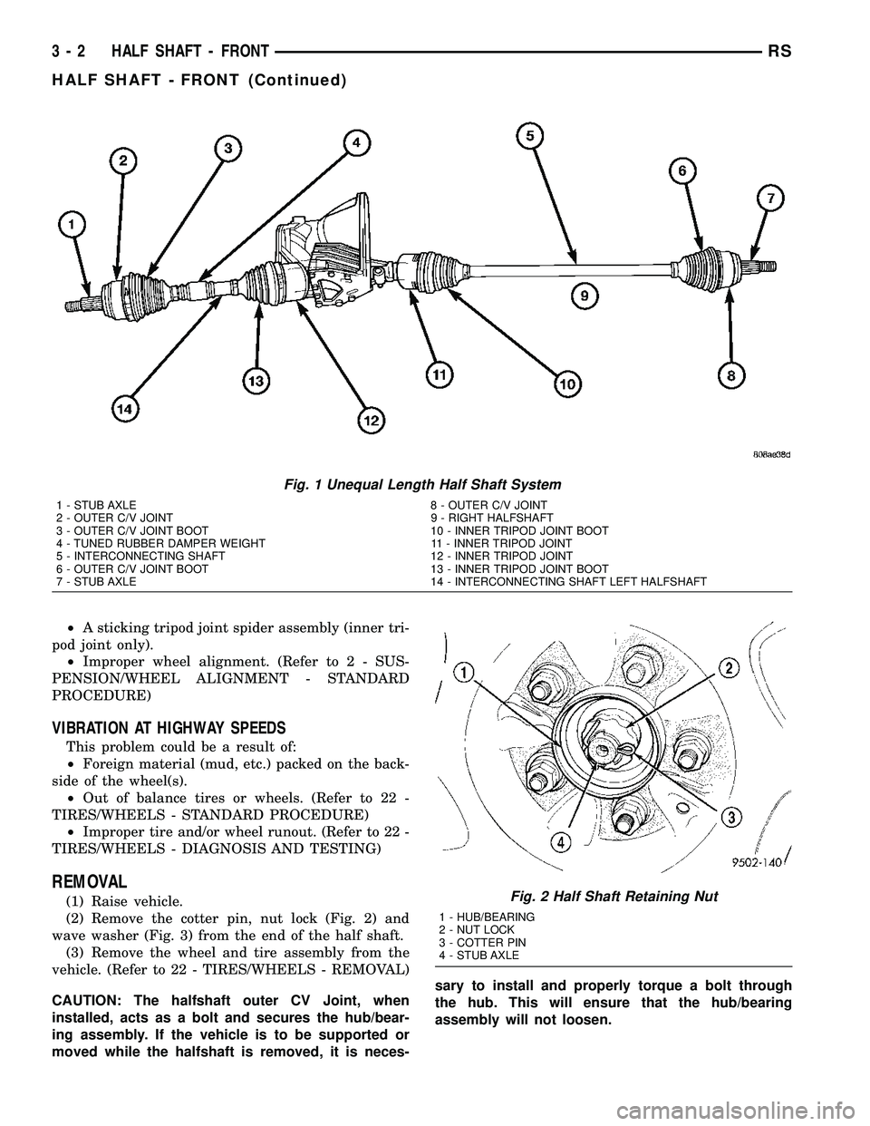
(2) Remove the cotter pin, nut lock (Fig. 2) and
wave washer (Fig. 3) from the end of the half shaft.
(3) Remove the wheel and tire assembly from the
vehicle. (Refer to 22 - TIRES/WHEELS - REMOVAL)
CAUTION: The halfshaft outer CV Joint, when
installed, acts as a bolt and secures the hub/bear-
ing assembly. If the vehicle is to be supported or
moved while the halfshaft is removed, it is neces-sary to install and properly torque a bolt through
the hub. This will ensure that the hub/bearing
assembly will not loosen.
Fig. 1 Unequal Length Half Shaft System
1 - STUB AXLE 8 - OUTER C/V JOINT
2 - OUTER C/V JOINT 9 - RIGHT HALFSHAFT
3 - OUTER C/V JOINT BOOT 10 - INNER TRIPOD JOINT BOOT
4 - TUNED RUBBER DAMPER WEIGHT 11 - INNER TRIPOD JOINT
5 - INTERCONNECTING SHAFT 12 - INNER TRIPOD JOINT
6 - OUTER C/V JOINT BOOT 13 - INNER TRIPOD JOINT BOOT
7 - STUB AXLE 14 - INTERCONNECTING SHAFT LEFT HALFSHAFT
Fig. 2 Half Shaft Retaining Nut
1 - HUB/BEARING
2 - NUT LOCK
3 - COTTER PIN
4 - STUB AXLE
3 - 2 HALF SHAFT - FRONTRS
HALF SHAFT - FRONT (Continued)
Page 102 of 2339
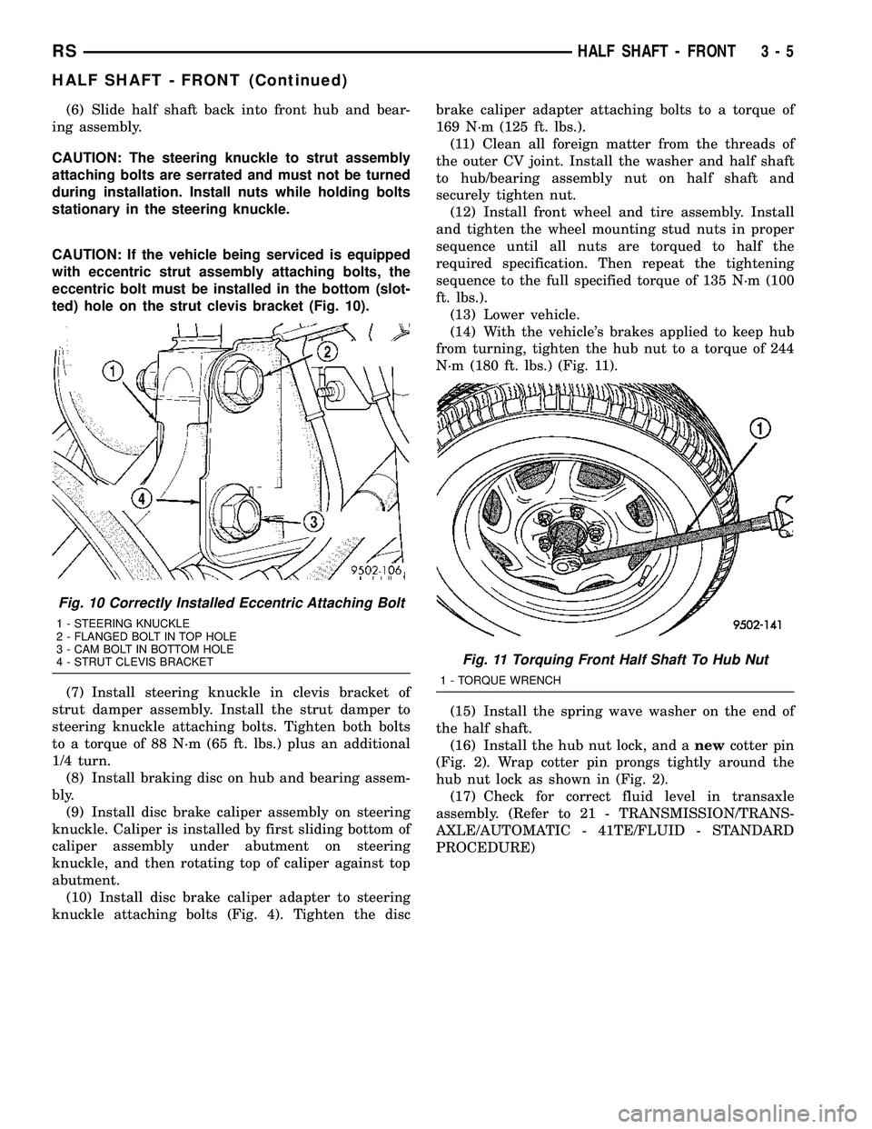
(6) Slide half shaft back into front hub and bear-
ing assembly.
CAUTION: The steering knuckle to strut assembly
attaching bolts are serrated and must not be turned
during installation. Install nuts while holding bolts
stationary in the steering knuckle.
CAUTION: If the vehicle being serviced is equipped
with eccentric strut assembly attaching bolts, the
eccentric bolt must be installed in the bottom (slot-
ted) hole on the strut clevis bracket (Fig. 10).
(7) Install steering knuckle in clevis bracket of
strut damper assembly. Install the strut damper to
steering knuckle attaching bolts. Tighten both bolts
to a torque of 88 N´m (65 ft. lbs.) plus an additional
1/4 turn.
(8) Install braking disc on hub and bearing assem-
bly.
(9) Install disc brake caliper assembly on steering
knuckle. Caliper is installed by first sliding bottom of
caliper assembly under abutment on steering
knuckle, and then rotating top of caliper against top
abutment.
(10) Install disc brake caliper adapter to steering
knuckle attaching bolts (Fig. 4). Tighten the discbrake caliper adapter attaching bolts to a torque of
169 N´m (125 ft. lbs.).
(11) Clean all foreign matter from the threads of
the outer CV joint. Install the washer and half shaft
to hub/bearing assembly nut on half shaft and
securely tighten nut.
(12) Install front wheel and tire assembly. Install
and tighten the wheel mounting stud nuts in proper
sequence until all nuts are torqued to half the
required specification. Then repeat the tightening
sequence to the full specified torque of 135 N´m (100
ft. lbs.).
(13) Lower vehicle.
(14) With the vehicle's brakes applied to keep hub
from turning, tighten the hub nut to a torque of 244
N´m (180 ft. lbs.) (Fig. 11).
(15) Install the spring wave washer on the end of
the half shaft.
(16) Install the hub nut lock, and anewcotter pin
(Fig. 2). Wrap cotter pin prongs tightly around the
hub nut lock as shown in (Fig. 2).
(17) Check for correct fluid level in transaxle
assembly. (Refer to 21 - TRANSMISSION/TRANS-
AXLE/AUTOMATIC - 41TE/FLUID - STANDARD
PROCEDURE)
Fig. 10 Correctly Installed Eccentric Attaching Bolt
1 - STEERING KNUCKLE
2 - FLANGED BOLT IN TOP HOLE
3 - CAM BOLT IN BOTTOM HOLE
4 - STRUT CLEVIS BRACKET
Fig. 11 Torquing Front Half Shaft To Hub Nut
1 - TORQUE WRENCH
RSHALF SHAFT - FRONT3-5
HALF SHAFT - FRONT (Continued)
Page 103 of 2339
SPECIFICATIONS - HALF SHAFT - FRONT
TORQUE SPECIFICATIONS
DESCRIPTION N´m Ft. Lbs. In. Lbs.
Bolts, Caliper Adapter to
Knuckle169 125 -
Nut, Hub 244 180 -
Nuts, Front Wheel Lug 135 100 -
Nut, Tie Rod End to
Knuckle75 55 -
Nut, Strut Clevis to
Knuckle81 +90É 60 +90É -
CV BOOT - INNER
REMOVAL
(1) Remove the half shaft requiring boot replace-
ment from the vehicle. (Refer to 3 - DIFFERENTIAL
& DRIVELINE/HALF SHAFT - REMOVAL)
(2) Remove large boot clamp which retains inner
tripod joint sealing boot to tripod joint housing and
discard.
(3) Remove small clamp which retains inner tripod
joint sealing boot to interconnecting shaft and dis-
card.
(4) Remove the sealing boot from the tripod hous-
ing and slide it down the interconnecting shaft.
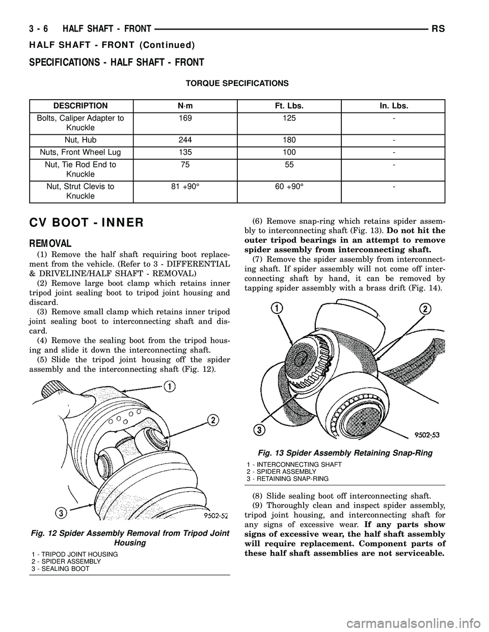
(5) Slide the tripod joint housing off the spider
assembly and the interconnecting shaft (Fig. 12).(6) Remove snap-ring which retains spider assem-
bly to interconnecting shaft (Fig. 13).Do not hit the
outer tripod bearings in an attempt to remove
spider assembly from interconnecting shaft.
(7) Remove the spider assembly from interconnect-
ing shaft. If spider assembly will not come off inter-
connecting shaft by hand, it can be removed by
tapping spider assembly with a brass drift (Fig. 14).
(8) Slide sealing boot off interconnecting shaft.
(9) Thoroughly clean and inspect spider assembly,
tripod joint housing, and interconnecting shaft for
any signs of excessive wear.If any parts show
signs of excessive wear, the half shaft assembly
will require replacement. Component parts of
these half shaft assemblies are not serviceable.
Fig. 12 Spider Assembly Removal from Tripod Joint
Housing
1 - TRIPOD JOINT HOUSING
2 - SPIDER ASSEMBLY
3 - SEALING BOOT
Fig. 13 Spider Assembly Retaining Snap-Ring
1 - INTERCONNECTING SHAFT
2 - SPIDER ASSEMBLY
3 - RETAINING SNAP-RING
3 - 6 HALF SHAFT - FRONTRS
HALF SHAFT - FRONT (Continued)