torque CHRYSLER VOYAGER 2005 Manual PDF
[x] Cancel search | Manufacturer: CHRYSLER, Model Year: 2005, Model line: VOYAGER, Model: CHRYSLER VOYAGER 2005Pages: 2339, PDF Size: 59.69 MB
Page 202 of 2339
(1) Make sure all hydraulic fluid lines are installed
and properly torqued.
(2) Connect the DRBIIItscan tool to the diagnos-
tics connector. The diagnostic connector is located
under the lower steering column cover to the left of
the steering column.
(3) Using the DRB, check to make sure the CAB
does not have any fault codes stored. If it does, clear
them using the DRB.
WARNING: WHEN BLEEDING THE BRAKE SYSTEM
WEAR SAFETY GLASSES. A CLEAR BLEED TUBE
MUST BE ATTACHED TO THE BLEEDER SCREWS
AND SUBMERGED IN A CLEAR CONTAINER FILLED
PART WAY WITH CLEAN BRAKE FLUID. DIRECT
THE FLOW OF BRAKE FLUID AWAY FROM YOUR-
SELF AND THE PAINTED SURFACES OF THE VEHI-
CLE. BRAKE FLUID AT HIGH PRESSURE MAY
COME OUT OF THE BLEEDER SCREWS WHEN
OPENED.
(4) Bleed the base brake system using the stan-
dard pressure or manual bleeding procedure. (Refer
to 5 - BRAKES - BASE - STANDARD PROCEDURE)
(5) Using the DRB, select ANTILOCK BRAKES,
followed by MISCELLANEOUS, then BLEED
BRAKES. Follow the instructions displayed. When
the scan tool displays TEST COMPLETED, discon-
nect the scan tool and proceed.
(6) Bleed the base brake system a second time.
Check brake fluid level in the reservoir periodically
to prevent emptying, causing air to enter the hydrau-
lic system.
(7) Fill the master cylinder reservoir to the full
level.
(8) Test drive the vehicle to be sure the brakes are
operating correctly and that the brake pedal does not
feel spongy.
SPECIFICATIONS
ABS FASTENER TORQUE
Refer to BRAKE FASTENER TORQUE. (Refer to 5
- BRAKES - BASE - SPECIFICATIONS)
TONE WHEEL RUNOUT
DESCRIPTION SPECIFICATION
Front Tone Wheel
Maximum Runout0.15 mm (0.006 in.)
Rear Tone Wheel
Maximum Runout0.15 mm (0.006 in.)
WHEEL SPEED SENSOR AIR GAP
DESCRIPTION SPECIFICATION
Front Sensor0.35 ± 1.20 mm
0.014 ± 0.047 in.
Rear Sensor0.40 ± 1.20 mm
0.016 ± 0.047 in.
FRONT WHEEL SPEED
SENSOR
REMOVAL
(1)Raise vehicle. (Refer to LUBRICATION & MAIN-
TENANCE/HOISTING - STANDARD PROCEDURE)
(2) Remove the tire and wheel assembly.
(3) Remove the sensor cable routing clamp screws.
CAUTION: When disconnecting the wheel speed
sensor from vehicle wiring harness, be careful not
to damage pins on connector
(4) Remove speed sensor cable grommets from
intermediate bracket on strut.
(5) Disconnect speed sensor cable from vehicle wir-
ing harness behind fender well shield.
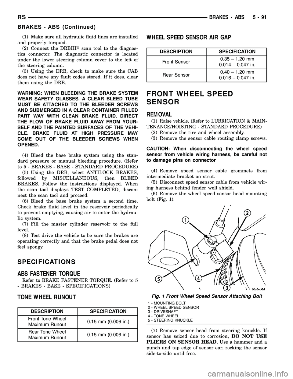
(6) Remove the wheel speed sensor head mounting
bolt (Fig. 1).
(7) Remove sensor head from steering knuckle. If
sensor has seized due to corrosion,DO NOT USE
PLIERS ON SENSOR HEAD.Use a hammer and a
punch and tap edge of sensor ear, rocking the sensor
side-to-side until free.
Fig. 1 Front Wheel Speed Sensor Attaching Bolt
1 - MOUNTING BOLT
2 - WHEEL SPEED SENSOR
3 - DRIVESHAFT
4 - TONE WHEEL
5 - STEERING KNUCKLE
RSBRAKES - ABS5-91
BRAKES - ABS (Continued)
Page 203 of 2339
(8) Remove front wheel speed sensor from vehicle.
INSTALLATION
CAUTION: Proper installation of wheel speed sen-
sor cables is critical to continued system operation.
Be sure that cables are installed in retainers. Fail-
ure to install cables in retainers as shown in this
section may result in contact with moving parts and
over extension of cables, resulting in an open cir-
cuit.
(1) Connect the front wheel speed sensor cable to
the vehicle wiring harness connector. Be sure speed
sensor cable connector is fully seated and locked into
vehicle wiring harness connector.
(2) Install the bolts attaching the routing clamps
to the body of the vehicle. Tighten the bolts to a
torque of 14 N´m (125 in. lbs.).
(3) Insert speed sensor cable grommets into inter-
mediate bracket on strut.
(4) Install the wheel speed sensor head mounting
bolt (Fig. 1). Tighten the bolt to a torque of 13 N´m
(115 in. lbs.)
(5) Install the wheel and tire assembly on vehicle.
(6) Lower vehicle.
(7) Road test vehicle to ensure proper operation of
the base and ABS brake systems.
REAR WHEEL SPEED SENSOR
-AWD
REMOVAL
(1) Raise vehicle. (Refer to LUBRICATION &
MAINTENANCE/HOISTING - STANDARD PROCE-
DURE)
CAUTION: When disconnecting speed sensor cable
from vehicle wiring harness be careful not to dam-
age pins on the electrical connectors. Also, inspect
connectors for any signs of previous damage.
(2) Remove grommet from floor pan of vehicle and
disconnect speed sensor cable connector from vehicle
wiring harness.
CAUTION: When removing rear wheel speed sensor
cable from routing clips, be sure not to damage the
routing clips. Routing clips that are molded onto
the brake hose will require replacement of the brake
hose if damaged during removal or installation of
the speed sensor cable.
(3) Carefully remove speed sensor cable from
press-in routing clips along brake hose and tubing.(4) Remove bolt securing wheel speed sensor cable
metal clip to rear of axle. Remove metal clip from
cable if necessary.
CAUTION: If speed sensor head has seized due to
corrosion, do not use pliers on speed sensor head
in an attempt to remove it. Use a hammer and a
punch and tap mounting flange edge side-to-side,
rocking the sensor until free.
(5) Remove wheel speed sensor head attaching
bolt.
(6) Remove wheel speed sensor head from the axle,
and remove sensor from vehicle.
INSTALLATION
CAUTION: Proper installation of wheel speed sen-
sor cables is critical to continued system operation.
Be sure that cables are installed in retainers. Fail-
ure to install cables in retainers as indicated may
result in contact with moving parts or over-exten-
sion of cables, resulting in an open circuit.
(1) Install wheel speed sensor head in axle flange.
CAUTION: Prior to installing the speed sensor head
attaching bolt, the plastic anti-rotation pin must be
fully seated into the bearing flange.
(2) Install wheel speed sensor head attaching bolt.
Tighten bolt to a torque 10 N´m (90 in. lbs.).
(3) Check the air gap between the face of the
wheel speed sensor and the top surface of the tone
wheel. (Refer to 5 - BRAKES - SPECIFICATIONS)
CAUTION: When installing wheel speed sensor
cable in the routing clips on rear brake flex hose,
be sure not to damage the routing clips. Routing
clips are molded onto the hose and will require
replacement of the brake hose if damaged.
(4) Install speed sensor cable under leaf spring
onto brake hose and tubing utilizing routing clips to
secure it in place.
(5) Install metal routing clip on speed sensor cable
and mount it to rear of axle with mounting bolt.
Tighten mounting bolt to 16 N´m (140 in. lbs.).
(6) Connect wheel speed sensor cable to vehicle
wiring harness.Be sure speed sensor cable con-
nector is fully seated and locked into vehicle
wiring harness connector.
(7) Install speed sensor cable grommet into the
floor pan, being sure the grommet is fully seated into
the access hole.
(8) Lower vehicle.
(9) Road test vehicle to ensure proper operation of
the base and ABS braking systems.
5 - 92 BRAKES - ABSRS
FRONT WHEEL SPEED SENSOR (Continued)
Page 217 of 2339
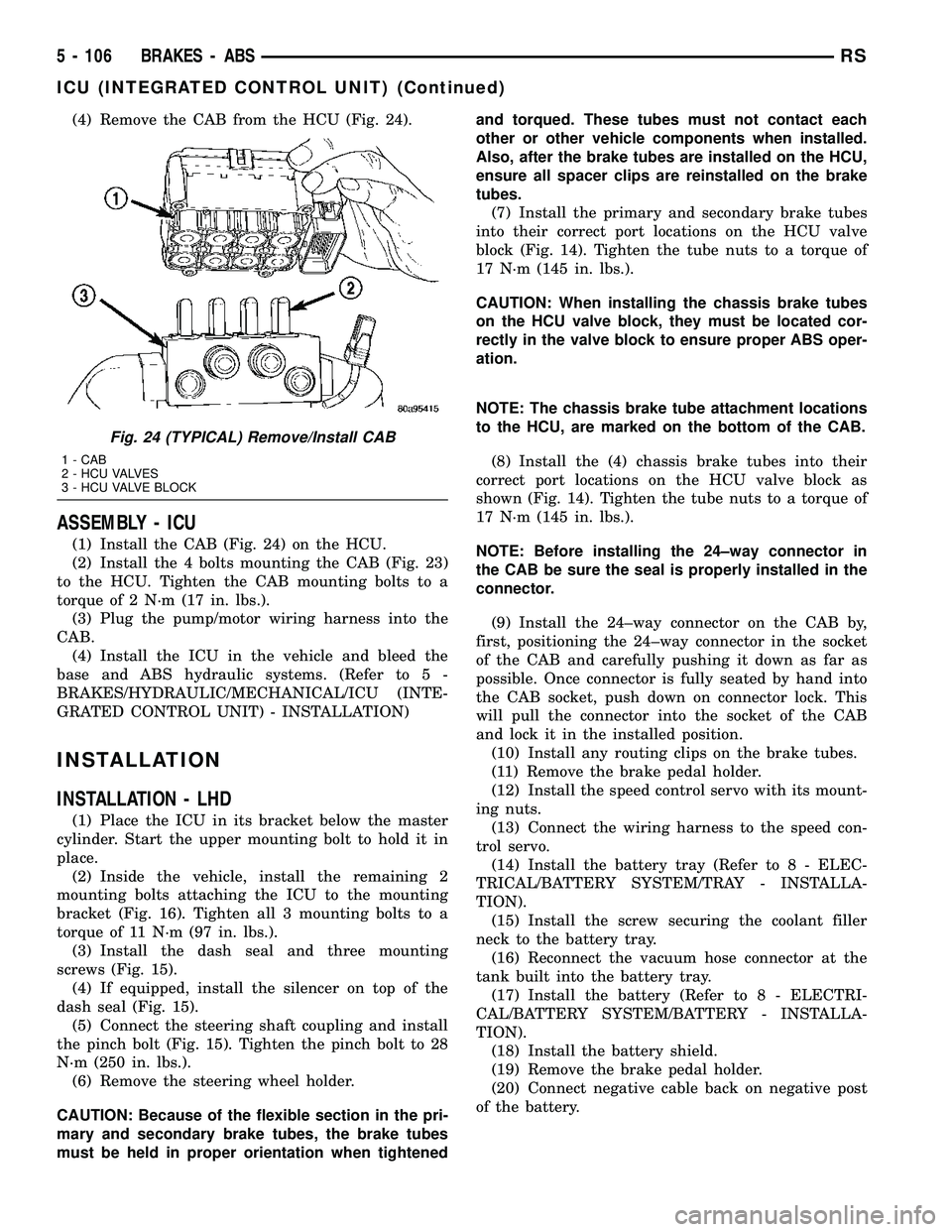
(4) Remove the CAB from the HCU (Fig. 24).
ASSEMBLY - ICU
(1) Install the CAB (Fig. 24) on the HCU.
(2) Install the 4 bolts mounting the CAB (Fig. 23)
to the HCU. Tighten the CAB mounting bolts to a
torque of 2 N´m (17 in. lbs.).
(3) Plug the pump/motor wiring harness into the
CAB.
(4) Install the ICU in the vehicle and bleed the
base and ABS hydraulic systems. (Refer to 5 -
BRAKES/HYDRAULIC/MECHANICAL/ICU (INTE-
GRATED CONTROL UNIT) - INSTALLATION)
INSTALLATION
INSTALLATION - LHD
(1) Place the ICU in its bracket below the master
cylinder. Start the upper mounting bolt to hold it in
place.
(2) Inside the vehicle, install the remaining 2
mounting bolts attaching the ICU to the mounting
bracket (Fig. 16). Tighten all 3 mounting bolts to a
torque of 11 N´m (97 in. lbs.).
(3) Install the dash seal and three mounting
screws (Fig. 15).
(4) If equipped, install the silencer on top of the
dash seal (Fig. 15).
(5) Connect the steering shaft coupling and install
the pinch bolt (Fig. 15). Tighten the pinch bolt to 28
N´m (250 in. lbs.).
(6) Remove the steering wheel holder.
CAUTION: Because of the flexible section in the pri-
mary and secondary brake tubes, the brake tubes
must be held in proper orientation when tightenedand torqued. These tubes must not contact each
other or other vehicle components when installed.
Also, after the brake tubes are installed on the HCU,
ensure all spacer clips are reinstalled on the brake
tubes.
(7) Install the primary and secondary brake tubes
into their correct port locations on the HCU valve
block (Fig. 14). Tighten the tube nuts to a torque of
17 N´m (145 in. lbs.).
CAUTION: When installing the chassis brake tubes
on the HCU valve block, they must be located cor-
rectly in the valve block to ensure proper ABS oper-
ation.
NOTE: The chassis brake tube attachment locations
to the HCU, are marked on the bottom of the CAB.
(8) Install the (4) chassis brake tubes into their
correct port locations on the HCU valve block as
shown (Fig. 14). Tighten the tube nuts to a torque of
17 N´m (145 in. lbs.).
NOTE: Before installing the 24±way connector in
the CAB be sure the seal is properly installed in the
connector.
(9) Install the 24±way connector on the CAB by,
first, positioning the 24±way connector in the socket
of the CAB and carefully pushing it down as far as
possible. Once connector is fully seated by hand into
the CAB socket, push down on connector lock. This
will pull the connector into the socket of the CAB
and lock it in the installed position.
(10) Install any routing clips on the brake tubes.
(11) Remove the brake pedal holder.
(12) Install the speed control servo with its mount-
ing nuts.
(13) Connect the wiring harness to the speed con-
trol servo.
(14) Install the battery tray (Refer to 8 - ELEC-
TRICAL/BATTERY SYSTEM/TRAY - INSTALLA-
TION).
(15) Install the screw securing the coolant filler
neck to the battery tray.
(16) Reconnect the vacuum hose connector at the
tank built into the battery tray.
(17) Install the battery (Refer to 8 - ELECTRI-
CAL/BATTERY SYSTEM/BATTERY - INSTALLA-
TION).
(18) Install the battery shield.
(19) Remove the brake pedal holder.
(20) Connect negative cable back on negative post
of the battery.
Fig. 24 (TYPICAL) Remove/Install CAB
1 - CAB
2 - HCU VALVES
3 - HCU VALVE BLOCK
5 - 106 BRAKES - ABSRS
ICU (INTEGRATED CONTROL UNIT) (Continued)
Page 218 of 2339
(21) Bleed the Base and ABS brake hydraulic sys-
tems (Refer to 5 - BRAKES - STANDARD PROCE-
DURE).
(22) Road test vehicle to ensure proper operation
of the base and antilock brake systems.
INSTALLATION - RHD
(1) Install the ICU on the mounting bracket (Fig.
21). Install the 3 bolts (Fig. 21) attaching the ICU to
the mounting bracket. Tighten the 3 mounting bolts
to a torque of 11 N´m (97 in. lbs.).
CAUTION: The ICU mounting bracket to front sus-
pension cradle mounting bolts have a unique corro-
sion protection coating and a special aluminum
washer. For this reason, only the original, or origi-
nal equipment Mopar replacement bolts can be
used to mount the ICU bracket to the front suspen-
sion crossmember.
(2) Install the ICU and its mounting bracket as an
assembly on the front suspension crossmember.
Install the 3 bolts attaching the ICU bracket to the
crossmember (Fig. 20). Tighten the 3 mounting bolts
to a torque of 28 N´m (250 in. lbs.).
CAUTION: Because of the flexible section in the pri-
mary and secondary brake tubes, and the brake
tubes between the HCU and the proportioning
valve, the brake tubes must be held in proper ori-
entation when tightened and torqued. These tubes
must not contact each other or other vehicle com-
ponents when installed. Also, after the brake tubes
are installed on the HCU, ensure all spacer clips are
reinstalled on the brake tubes.
CAUTION: When installing the chassis brake tubes
on the HCU valve block, they must be located cor-
rectly in the valve block to ensure proper ABS oper-
ation. Refer to (Fig. 19) for the correct chassis
brake tube locations.
NOTE: The chassis brake tube attachment locations
to the HCU, are marked on the bottom of the ICU
mounting bracket.
(3) Install the 6 chassis brake tubes into their cor-
rect port locations on the HCU valve block as shown
in (Fig. 19). Tighten the tube nuts to a torque of 17
N´m (145 in. lbs.).
NOTE: Before installing the 24-way connector in the
CAB be sure the seal is properly installed in the
connector.(4) Install the 24-way connector (Fig. 17) on the
CAB using the following procedure. Position the
24-way connector in the socket of the CAB and care-
fully push it down as far as possible. When connector
is fully seated by hand into the CAB socket, push in
the connector lock (Fig. 18). This will pull the connec-
tor into the socket of the CAB and lock it in the
installed position.
NOTE: The CAB wiring harness must be clipped to
the ICU mounting bracket. This will ensure the wir-
ing harness is properly routed and does not contact
the brake tubes or the body of the vehicle.
(5) Clip the cab wiring harness (Fig. 17) to the
ICU mounting bracket.
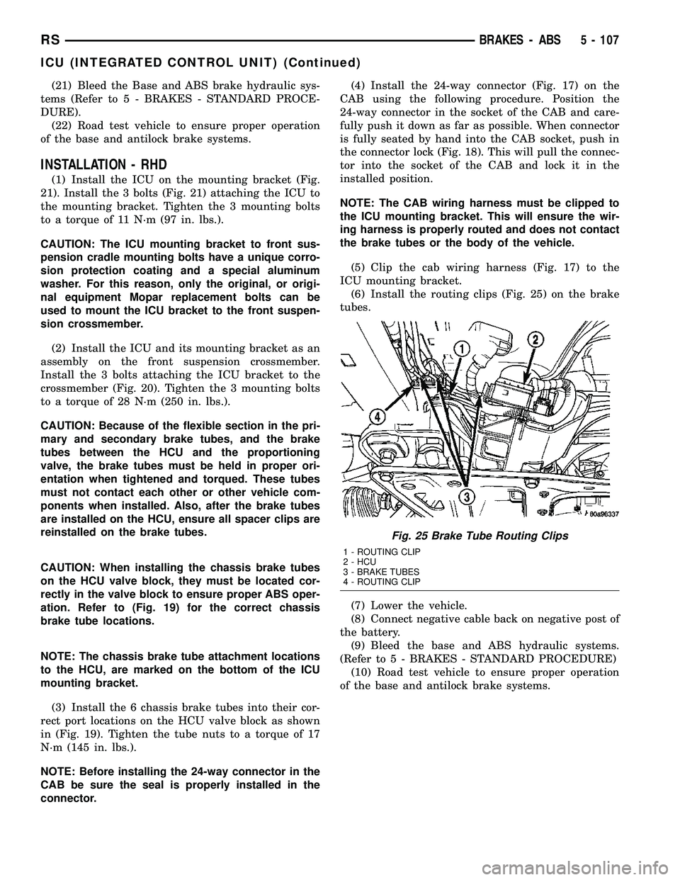
(6) Install the routing clips (Fig. 25) on the brake
tubes.
(7) Lower the vehicle.
(8) Connect negative cable back on negative post of
the battery.
(9) Bleed the base and ABS hydraulic systems.
(Refer to 5 - BRAKES - STANDARD PROCEDURE)
(10) Road test vehicle to ensure proper operation
of the base and antilock brake systems.
Fig. 25 Brake Tube Routing Clips
1 - ROUTING CLIP
2 - HCU
3 - BRAKE TUBES
4 - ROUTING CLIP
RSBRAKES - ABS5 - 107
ICU (INTEGRATED CONTROL UNIT) (Continued)
Page 220 of 2339
COOLING
TABLE OF CONTENTS
page page
COOLING
DESCRIPTION
DESCRIPTION - COOLING SYSTEM........1
DESCRIPTION - HOSE CLAMPS...........1
OPERATION
OPERATION - COOLING SYSTEM.........2
OPERATION - HOSE CLAMPS............2
DIAGNOSIS AND TESTING
DIAGNOSIS AND TESTING - COOLING
SYSTEM LEAK TEST....................2
DIAGNOSIS AND TESTING - COOLING
SYSTEM FLOW CHECK.................3
DIAGNOSIS AND TESTING - COOLING
SYSTEM AERATION....................4
DIAGNOSIS AND TESTING - COOLING
SYSTEM DEAERATION..................4
STANDARD PROCEDURE
STANDARD PROCEDURE - COOLING
SYSTEM DRAINING....................4STANDARD PROCEDURE - COOLING
SYSTEM FILLING......................4
STANDARD PROCEDURE - ADDING
ADDITIONAL COOLANT.................4
STANDARD PROCEDURE - COOLANT
LEVEL CHECK........................4
SPECIFICATIONS
ACCESSORY DRIVE BELT TENSION.......5
TORQUE.............................5
SPECIAL TOOLS
COOLING SYSTEM.....................6
ACCESSORY DRIVE.......................7
ENGINE...............................13
TRANSMISSION.........................38
COOLING
DESCRIPTION
DESCRIPTION - COOLING SYSTEM
The cooling system components consist of a radia-
tor, electric fan motors, shroud, pressure cap, thermo-
stat, transmission oil cooler, water pump, hoses,
clamps, coolant, and a coolant reserve system to com-
plete the circuit.
DESCRIPTION - HOSE CLAMPS
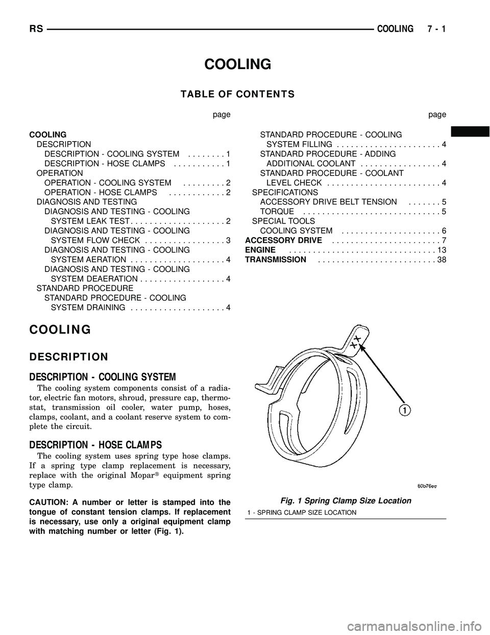
The cooling system uses spring type hose clamps.
If a spring type clamp replacement is necessary,
replace with the original Mopartequipment spring
type clamp.
CAUTION: A number or letter is stamped into the
tongue of constant tension clamps. If replacement
is necessary, use only a original equipment clamp
with matching number or letter (Fig. 1).
Fig. 1 Spring Clamp Size Location
1 - SPRING CLAMP SIZE LOCATION
RSCOOLING7-1
Page 224 of 2339
SPECIFICATIONS
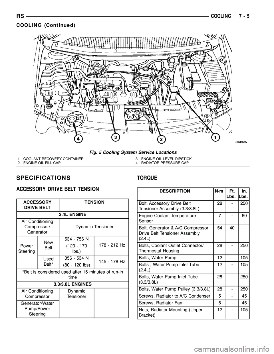
ACCESSORY DRIVE BELT TENSION
ACCESSORY
DRIVE BELTTENSION
2.4L ENGINE
Air Conditioning
Compressor/
GeneratorDynamic Tensioner
Power
SteeringNew
Belt534 - 756 N
178 - 212 Hz
(120 - 170
lbs.)
Used
Belt*356 - 534 N
145 - 178 Hz
(80 - 120 lbs)
*Belt is considered used after 15 minutes of run-in
time
3.3/3.8L ENGINES
Air Conditioning
CompressorDynamic
Tensioner
Generator/Water
Pump/Power
Steering
TORQUE
DESCRIPTION N´m Ft.
Lbs.In.
Lbs.
Bolt, Accessory Drive Belt
Tensioner Assembly (3.3/3.8L)28 - 250
Engine Coolant Temperature
Sensor7-60
Bolt, Generator & A/C Compressor
Drive Belt Tensioner Assembly
(2.4L)54 40 -
Bolts, Coolant Outlet Connector/
Thermostat Housing28 - 250
Bolts, Water Pump 12 - 105
Bolts , Water Pump Inlet Tube
(2.4L)12 - 105
Bolts, Water Pump Inlet Tube
(3.3/3.8L)28 - 250
Bolts, Water Pump Pulley (3.3/3.8L) 28 - 250
Screws, Radiator to A/C Condenser 5 - 45
Screws, Radiator Fan 5 - 45
Nuts, Radiator Mounting (Upper
Bracket)12 - 105
Fig. 5 Cooling System Service Locations
1 - COOLANT RECOVERY CONTAINER 3 - ENGINE OIL LEVEL DIPSTICK
2 - ENGINE OIL FILL CAP 4 - RADIATOR PRESSURE CAP
RSCOOLING7-5
COOLING (Continued)
Page 229 of 2339
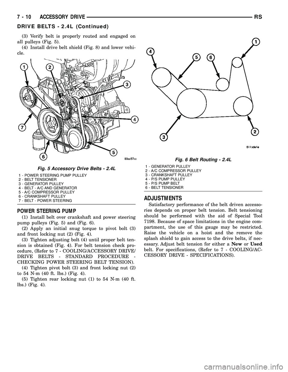
(3) Verify belt is properly routed and engaged on
all pulleys (Fig. 5).
(4) Install drive belt shield (Fig. 8) and lower vehi-
cle.
POWER STEERING PUMP
(1) Install belt over crankshaft and power steering
pump pulleys (Fig. 5) and (Fig. 6).
(2) Apply an initial snug torque to pivot bolt (3)
and front locking nut (2) (Fig. 4).
(3) Tighten adjusting bolt (4) until proper belt ten-
sion is obtained (Fig. 4). For belt tension check pro-
cedure, (Refer to 7 - COOLING/ACCESSORY DRIVE/
DRIVE BELTS - STANDARD PROCEDURE -
CHECKING POWER STEERING BELT TENSION).
(4) Tighten pivot bolt (3) and front locking nut (2)
to 54 N´m (40 ft. lbs.) (Fig. 4).
(5) Tighten rear locking nut (1) to 54 N´m (40 ft.
lbs.) (Fig. 4).
ADJUSTMENTS
Satisfactory performance of the belt driven accesso-
ries depends on proper belt tension. Belt tensioning
should be performed with the aid of Special Tool
7198. Because of space limitations in the engine com-
partment, the use of this gauge may be restricted.
Raise the vehicle on a hoist and the remove the
splash shield to gain access to the drive belts, if nec-
essary. Adjust belt tension for either aNeworUsed
belt. For specifications, (Refer to 7 - COOLING/AC-
CESSORY DRIVE - SPECIFICATIONS).
Fig. 5 Accessory Drive Belts - 2.4L
1 - POWER STEERING PUMP PULLEY
2 - BELT TENSIONER
3 - GENERATOR PULLEY
4 - BELT - A/C AND GENERATOR
5 - A/C COMPRESSOR PULLEY
6 - CRANKSHAFT PULLEY
7 - BELT - POWER STEERING
Fig. 6 Belt Routing - 2.4L
1 - GENERATOR PULLEY
2 - A/C COMPRESSOR PULLEY
3 - CRANKSHAFT PULLEY
4 - P/S PUMP PULLEY
5 - P/S PUMP BELT
6 - BELT TENSIONER
7 - 10 ACCESSORY DRIVERS
DRIVE BELTS - 2.4L (Continued)
Page 251 of 2339
WATER PUMP - 2.4L
DESCRIPTION
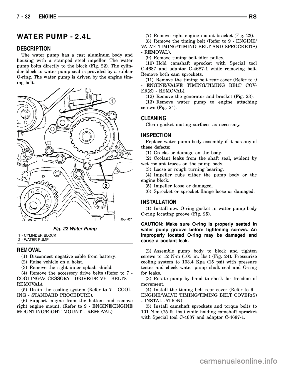
The water pump has a cast aluminum body and
housing with a stamped steel impeller. The water
pump bolts directly to the block (Fig. 22). The cylin-
der block to water pump seal is provided by a rubber
O-ring. The water pump is driven by the engine tim-
ing belt.
REMOVAL
(1) Disconnect negative cable from battery.
(2) Raise vehicle on a hoist.
(3) Remove the right inner splash shield.
(4) Remove the accessory drive belts (Refer to 7 -
COOLING/ACCESSORY DRIVE/DRIVE BELTS -
REMOVAL).
(5) Drain the cooling system (Refer to 7 - COOL-
ING - STANDARD PROCEDURE).
(6) Support engine from the bottom and remove
right engine mount. (Refer to 9 - ENGINE/ENGINE
MOUNTING/RIGHT MOUNT - REMOVAL).(7) Remove right engine mount bracket (Fig. 23).
(8) Remove the timing belt (Refer to 9 - ENGINE/
VALVE TIMING/TIMING BELT AND SPROCKET(S)
- REMOVAL).
(9) Remove timing belt idler pulley.
(10) Hold camshaft sprocket with Special tool
C-4687 and adaptor C-4687-1 while removing bolt.
Remove both cam sprockets.
(11) Remove the timing belt rear cover (Refer to 9
- ENGINE/VALVE TIMING/TIMING BELT COV-
ER(S) - REMOVAL).
(12) Remove the generator and bracket (Fig. 23).
(13) Remove water pump to engine attaching
screws (Fig. 24).
CLEANING
Clean gasket mating surfaces as necessary.
INSPECTION
Replace water pump body assembly if it has any of
these defects:
(1) Cracks or damage on the body.
(2) Coolant leaks from the shaft seal, evident by
wet coolant traces on the pump body.
(3) Loose or rough turning bearing.
(4) Impeller rubs either the pump body or the
engine block.
(5) Impeller loose or damaged.
(6) Sprocket or sprocket flange loose or damaged.
INSTALLATION
(1) Install new O-ring gasket in water pump body
O-ring locating groove (Fig. 25).
CAUTION: Make sure O-ring is properly seated in
water pump groove before tightening screws. An
improperly located O-ring may be damaged and
cause a coolant leak.
(2) Assemble pump body to block and tighten
screws to 12 N´m (105 in. lbs.) (Fig. 24). Pressurize
cooling system to 103.4 Kpa (15 psi) with pressure
tester and check water pump shaft seal and O-ring
for leaks.
(3) Rotate pump by hand to check for freedom of
movement.
(4) Install the timing belt rear cover (Refer to 9 -
ENGINE/VALVE TIMING/TIMING BELT COVER(S)
- INSTALLATION).
(5) Install camshaft sprockets and torque bolts to
101 N´m (75 ft. lbs.) while holding camshaft sprocket
with Special tool C-4687 and adaptor C-4687-1.
Fig. 22 Water Pump
1 - CYLINDER BLOCK
2 - WATER PUMP
7 - 32 ENGINERS
Page 252 of 2339
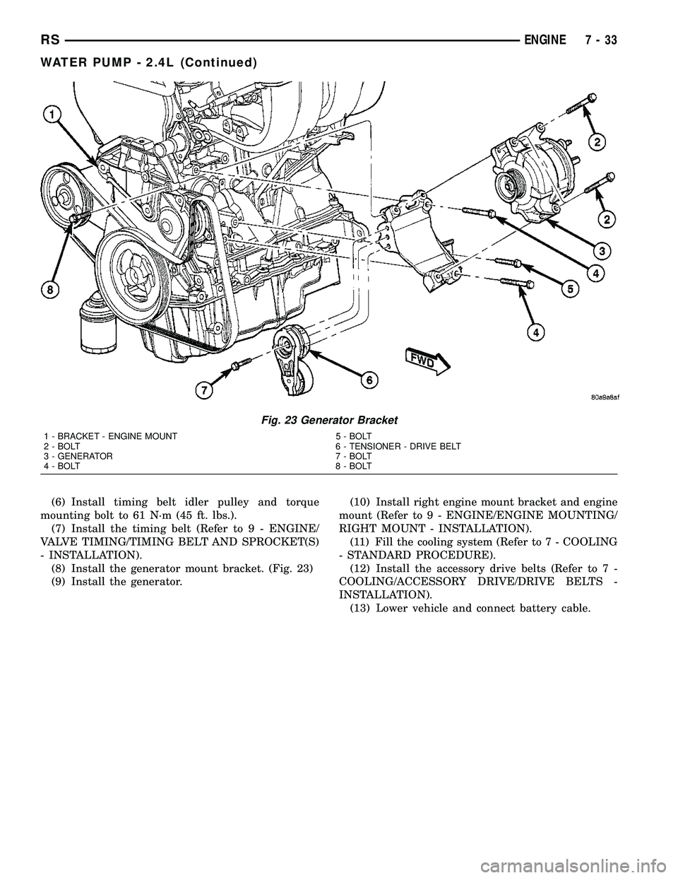
(6) Install timing belt idler pulley and torque
mounting bolt to 61 N´m (45 ft. lbs.).
(7) Install the timing belt (Refer to 9 - ENGINE/
VALVE TIMING/TIMING BELT AND SPROCKET(S)
- INSTALLATION).
(8) Install the generator mount bracket. (Fig. 23)
(9) Install the generator.(10) Install right engine mount bracket and engine
mount (Refer to 9 - ENGINE/ENGINE MOUNTING/
RIGHT MOUNT - INSTALLATION).
(11) Fill the cooling system (Refer to 7 - COOLING
- STANDARD PROCEDURE).
(12) Install the accessory drive belts (Refer to 7 -
COOLING/ACCESSORY DRIVE/DRIVE BELTS -
INSTALLATION).
(13) Lower vehicle and connect battery cable.
Fig. 23 Generator Bracket
1 - BRACKET - ENGINE MOUNT 5 - BOLT
2 - BOLT 6 - TENSIONER - DRIVE BELT
3 - GENERATOR 7 - BOLT
4 - BOLT 8 - BOLT
RSENGINE7-33
WATER PUMP - 2.4L (Continued)
Page 285 of 2339
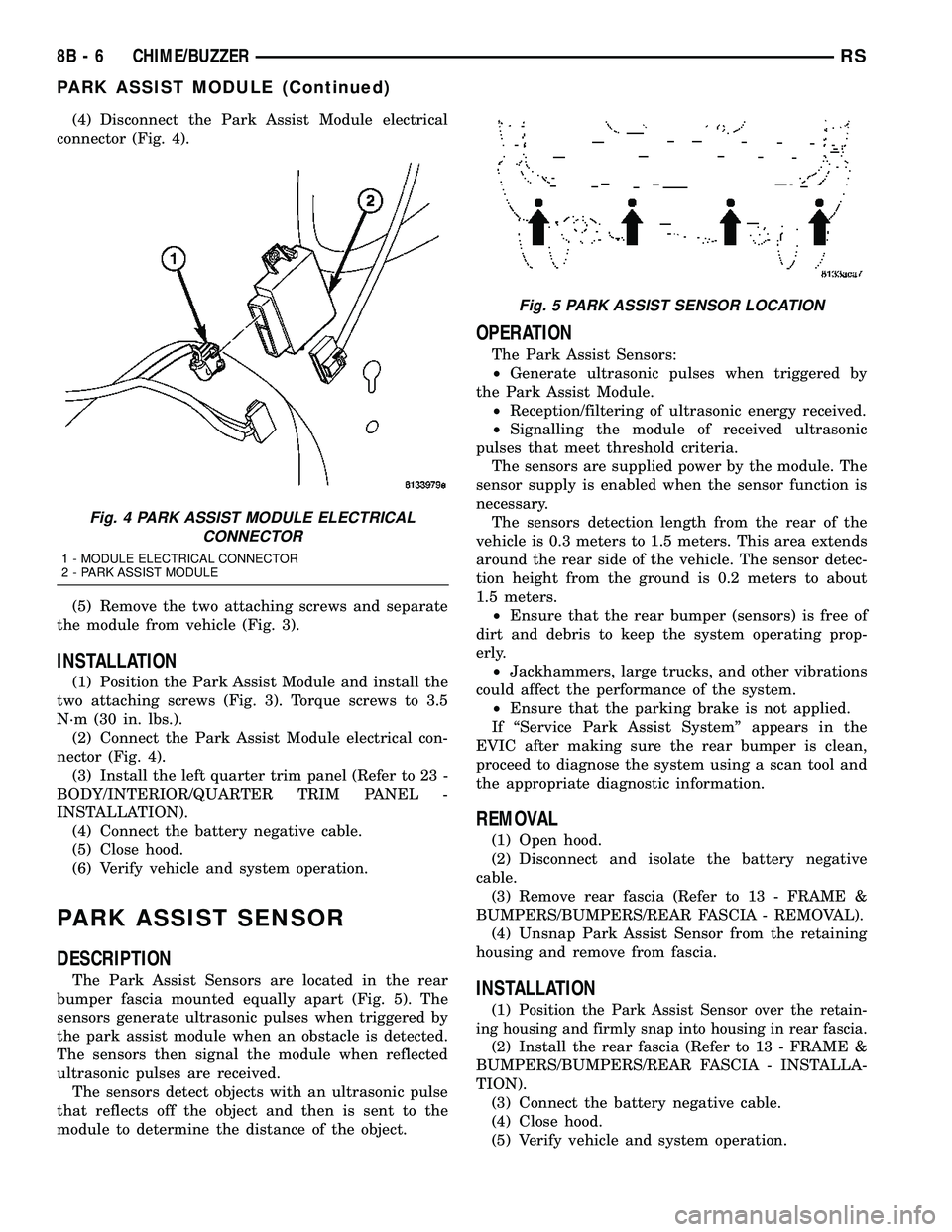
(4) Disconnect the Park Assist Module electrical
connector (Fig. 4).
(5) Remove the two attaching screws and separate
the module from vehicle (Fig. 3).
INSTALLATION
(1) Position the Park Assist Module and install the
two attaching screws (Fig. 3). Torque screws to 3.5
N´m (30 in. lbs.).
(2) Connect the Park Assist Module electrical con-
nector (Fig. 4).
(3) Install the left quarter trim panel (Refer to 23 -
BODY/INTERIOR/QUARTER TRIM PANEL -
INSTALLATION).
(4) Connect the battery negative cable.
(5) Close hood.
(6) Verify vehicle and system operation.
PARK ASSIST SENSOR
DESCRIPTION
The Park Assist Sensors are located in the rear
bumper fascia mounted equally apart (Fig. 5). The
sensors generate ultrasonic pulses when triggered by
the park assist module when an obstacle is detected.
The sensors then signal the module when reflected
ultrasonic pulses are received.
The sensors detect objects with an ultrasonic pulse
that reflects off the object and then is sent to the
module to determine the distance of the object.
OPERATION
The Park Assist Sensors:
²Generate ultrasonic pulses when triggered by
the Park Assist Module.
²Reception/filtering of ultrasonic energy received.
²Signalling the module of received ultrasonic
pulses that meet threshold criteria.
The sensors are supplied power by the module. The
sensor supply is enabled when the sensor function is
necessary.
The sensors detection length from the rear of the
vehicle is 0.3 meters to 1.5 meters. This area extends
around the rear side of the vehicle. The sensor detec-
tion height from the ground is 0.2 meters to about
1.5 meters.
²Ensure that the rear bumper (sensors) is free of
dirt and debris to keep the system operating prop-
erly.
²Jackhammers, large trucks, and other vibrations
could affect the performance of the system.
²Ensure that the parking brake is not applied.
If ªService Park Assist Systemº appears in the
EVIC after making sure the rear bumper is clean,
proceed to diagnose the system using a scan tool and
the appropriate diagnostic information.
REMOVAL
(1) Open hood.
(2) Disconnect and isolate the battery negative
cable.
(3) Remove rear fascia (Refer to 13 - FRAME &
BUMPERS/BUMPERS/REAR FASCIA - REMOVAL).
(4) Unsnap Park Assist Sensor from the retaining
housing and remove from fascia.
INSTALLATION
(1)Position the Park Assist Sensor over the retain-
ing housing and firmly snap into housing in rear fascia.
(2) Install the rear fascia (Refer to 13 - FRAME &
BUMPERS/BUMPERS/REAR FASCIA - INSTALLA-
TION).
(3) Connect the battery negative cable.
(4) Close hood.
(5) Verify vehicle and system operation.
Fig. 4 PARK ASSIST MODULE ELECTRICAL
CONNECTOR
1 - MODULE ELECTRICAL CONNECTOR
2 - PARK ASSIST MODULE
Fig. 5 PARK ASSIST SENSOR LOCATION
8B - 6 CHIME/BUZZERRS
PARK ASSIST MODULE (Continued)