CHRYSLER VOYAGER 2005 Service Manual
Manufacturer: CHRYSLER, Model Year: 2005, Model line: VOYAGER, Model: CHRYSLER VOYAGER 2005Pages: 2339, PDF Size: 59.69 MB
Page 431 of 2339

STANDARD PROCEDURE
LIFTGATE ADJUSTMENT
In order for the power liftgate system to function
properly the liftgate must move freely and smoothly.
The power liftgate system can accommodate for some
minor changes in the effort required to move the lift-
gate. However, in extreme conditions the liftgate may
need to be mechanically adjusted for proper fit and
finish. (Refer to 23 - BODY/DECKLID/HATCH/LIFT-
GATE/TAILGATE/LIFTGATE - INSTALLATION) for
detailed instructions.
If a problem exists with the power liftgate and it is
suspected to be extreme effort, check the liftgate prop
rods and hinges for free movement.
NOTE: Routine application of Mopar MP-50Tor
equivalent on the chrome prop rod shafts and lift-
gate latch and hinges will help keep the liftgate in
good working order.
POWER LIFTGATE LEARN CYCLE
Any time a power liftgate component is removed,
replaced or a liftgate adjustment is performed a learn
cycle must be performed. This learn cycle enables the
power liftgate control module to learn or relearn
information (travel limits, resistance to door travel,
etc.) which allows it to perform properly and safely.
Perform the following to complete a power liftgate
learn cycle:
(1) Obtain a DRBIIIt, or equivalent scan tool.
(2) Connect the scan tool to the vehicle and check
for any power liftgate system stored Diagnostic Trou-
ble Codes (DTCs), correct and erase any stored
DTCs.
(3) Using the scan tool, Go into Test Routine Menu
and select the power open command.
(4) Select the power close command.
(5) The liftgate learn cycle is complete.
If a DRBIIItor equivalent scan tool is not avail-
able, the learn cycle can be performed by actuating
the liftgate using any of the normal command
switches. Be certain to cycle the liftgate through a
complete open and close cycle before returning the
vehicle to service.
NOTE: If the power liftgate will not complete a full
cycle a problem exists with the power liftgate sys-
tem. (Refer to 8 - ELECTRICAL/POWER DOORS -
DIAGNOSIS AND TESTING).
CHIME/THERMISTOR
DESCRIPTION
The chime/thermistor assembly is a small capacitor
shaped electrical component mounted to the rear
license plate lamp housing assembly (Fig. 2) , located
just above the license plate. The chime portion of the
assembly controls the audible chime sound heard at
the rear of the vehicle when the power liftgate is in
motion. The thermistor portion of the assembly is a
temperature sensor, used by the power liftgate con-
trol module. The chime/thermistor assembly is a ser-
viceable component.
OPERATION
The chime/thermistor assembly performs two dif-
ferent functions for the power liftgate system. First,
the chime portion provides an audible chime sound
which is controlled by the power liftgate control mod-
ule. The chime/thermistor assembly is hardwired to
the power liftgate control module. Second the ther-
mistor provides a outside temperature reading by
way of a resistance reading supplied to the power
liftgate control module. As temperature increases the
resistance reading increases, as temperature
decreases the resistance reading decreases.
REMOVAL
(1) Disconnect and isolate the battery negative
cable.
Fig. 2 REAR LIGHT BAR
1 - CHIME / THERMISTOR
2 - ELECTRIC RELEASE HANDLE SWITCH
3 - LICENSE PLATE LAMPS
8N - 8 POWER LIFTGATE SYSTEMRS
POWER LIFTGATE SYSTEM (Continued)
Page 432 of 2339

(2) Remove the rear light bar assembly from the
vehicle. (Refer to 8 - ELECTRICAL/POWER DOORS/
SWITCH - REMOVAL) for the procedure.
(3) Grasp the light bar at its sides next to ther-
mistor/chime assembly and gently pull the two sides
of the light bar apart until the thermistor/chime
assembly can be removed.
INSTALLATION
(1) Gently pull the two sides of the light bar apart
until the thermistor/chime assembly can be installed.
(2) Install the rear light bar assembly on the vehi-
cle. (Refer to 8 - ELECTRICAL/POWER DOORS/
SWITCH - INSTALLATION) for the procedure.
(3) Connect the battery negative cable.
ENGAGE ACTUATOR
DESCRIPTION
The 12 volt engage actuator (Fig. 3) provides the
engagement and disengagement of the liftgate gear
motor to the lift gear by way of an over center link,
activated by a lever.
The engage actuator is a serviceable component
and cannot be repaired, if found to be inoperative it
must be replaced.
OPERATION
The engage actuators normal position is disen-
gaged. When a power liftgate open or close command
is generated from any of the command switches, the
power liftgate control module signals the engage
actuator to move its lever to the engaged position.
This engages the gear motor to the lift gear, so when
the motor turns the lift gate moves upward or down-
wards depending on its current position.
During a manual liftgate open or close cycle the
engage actuator is disengaged, allowing unrestricted
liftgate movement.
REMOVAL
(1) Disconnect and isolate the battery negative
cable.
(2) Remove the left rear D-pillar trim from the
vehicle, (Refer to 23 - BODY/INTERIOR/LEFT
D-PILLAR TRIM PANEL - REMOVAL).
(3) Manually engage the actuator link rod, this
must be done to access one of the engage actuator
retaining screws.
(4) Remove the two engage actuator retaining
screws (Fig. 4).
(5) Disconnect the engage actuator electrical con-
nector and remove the engage actuator from the
vehicle.
Fig. 3 LIFTGATE GEAR MOTOR ASSEMBLY
1 - TRANSVERSE BRACKET
2 - ENGAGE ACTUATOR
3 - LIFT GEAR AND ROD ASSEMBLY
4 - LIFTGATE MOTOR
Fig. 4 LIFTGATE GEAR MOTOR ASSEMBLY
1 - ENGAGE ACTUATOR RETAINING SCREWS
2 - LIFT GEAR RETAINING BOLTS
RSPOWER LIFTGATE SYSTEM8N-9
CHIME/THERMISTOR (Continued)
Page 433 of 2339
INSTALLATION
(1) Position the engage actuator in the vehicle and
connect the engage actuator electrical connector.
(2) Install the two engage actuator retaining
screws.
(3) Manually disengage the actuator.
(4) Install the left rear D-pillar trim on the vehi-
cle, (Refer to 23 - BODY/INTERIOR/LEFT D-PILLAR
TRIM PANEL - INSTALLATION).
(5) Connect the battery negative cable.
(6) Using an appropriate scan tool, check and
erase any power liftgate control module diagnostic
trouble codes.
(7) Verify power liftgate system and engage actua-
tor operation. Cycle the power liftgate through one
complete open and close cycle.
EXTERIOR HANDLE SWITCH
DESCRIPTION
The exterior handle switch is an electronic release
switch mounted to the rear license plate lamp hous-
ing assembly, located just above the license plate.
This switch controls the power liftgate release func-
tion and is also capable of reversing the power lift-
gate when it is in motion. A full power open cycle
cannot be performed using this switch, only one of
the power open command switches (key fob and over-
head console mounted) can be used to perform a full
power open cycle. The exterior handle switch is a ser-
viceable component.
OPERATION
When the exterior handle switch is depressed, with
the liftgate in the closed position, a message is sent
to the Body Control Module (BCM). The BCM then
sends a signal to the power liftgate control module
via the Programmable Communication Interface
(PCI) data bus circuit. The power liftgate control
module then sends a signal to the power latch
mounted actuator, which moves the liftgate from the
primary closed and latched position to the open and
movable position. If the liftgate is not pulled open
once the latch releases within a few seconds, the
latch will cinch closed again.
REMOVAL
(1) Disconnect and isolate the battery negative
cable.
(2) Open the liftgate and remove the liftgate trim
panel, (Refer to 23 - BODY/DECKLID/HATCH/LIFT-
GATE/TAILGATE/TRIM PANEL - REMOVAL).
(3) Remove the rear lamp bar assembly from the
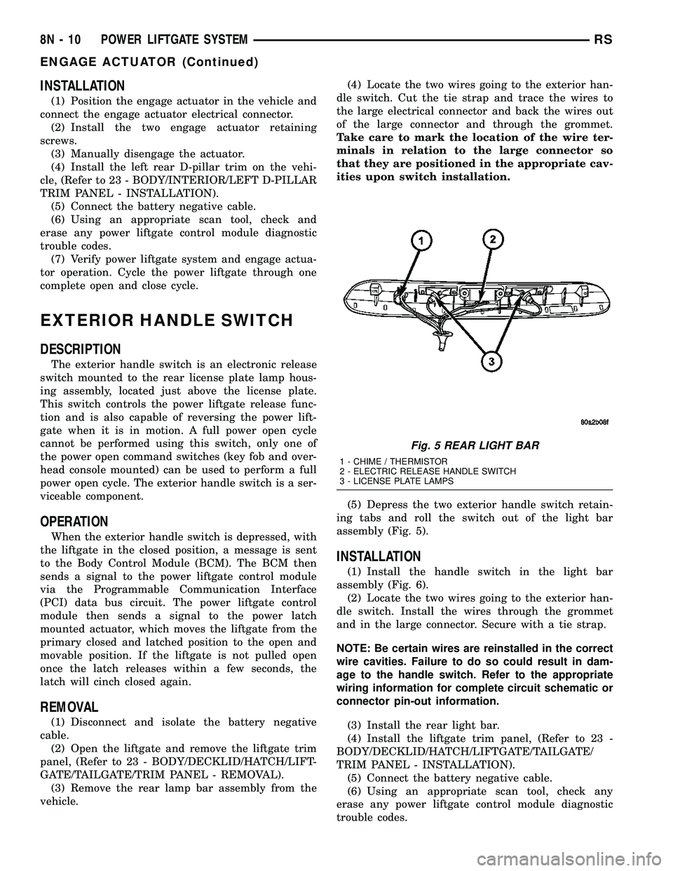
vehicle.(4) Locate the two wires going to the exterior han-
dle switch. Cut the tie strap and trace the wires to
the large electrical connector and back the wires out
of the large connector and through the grommet.
Take care to mark the location of the wire ter-
minals in relation to the large connector so
that they are positioned in the appropriate cav-
ities upon switch installation.
(5) Depress the two exterior handle switch retain-
ing tabs and roll the switch out of the light bar
assembly (Fig. 5).
INSTALLATION
(1) Install the handle switch in the light bar
assembly (Fig. 6).
(2) Locate the two wires going to the exterior han-
dle switch. Install the wires through the grommet
and in the large connector. Secure with a tie strap.
NOTE: Be certain wires are reinstalled in the correct
wire cavities. Failure to do so could result in dam-
age to the handle switch. Refer to the appropriate
wiring information for complete circuit schematic or
connector pin-out information.
(3) Install the rear light bar.
(4) Install the liftgate trim panel, (Refer to 23 -
BODY/DECKLID/HATCH/LIFTGATE/TAILGATE/
TRIM PANEL - INSTALLATION).
(5) Connect the battery negative cable.
(6) Using an appropriate scan tool, check any
erase any power liftgate control module diagnostic
trouble codes.
Fig. 5 REAR LIGHT BAR
1 - CHIME / THERMISTOR
2 - ELECTRIC RELEASE HANDLE SWITCH
3 - LICENSE PLATE LAMPS
8N - 10 POWER LIFTGATE SYSTEMRS
ENGAGE ACTUATOR (Continued)
Page 434 of 2339

(7) Verify power liftgate system and handle switch
operation. Cycle the power liftgate through one com-
plete open and close cycle, this will allow the power
liftgate control module to relearn its cycle with the
new components.
FULL OPEN SWITCH
DESCRIPTION
The full open switch is located on the gear motor
housing (Fig. 7) and is used to signal the power lift-
gate control module when the power liftgate is in the
full open position. Two wires are used from the full
open switch contacts to the gear motor assemblies
main electrical connector. The full open switch is a
serviceable component.
OPERATION
When the power liftgate reaches the full open posi-
tion, the gear motor housing mounted full open
switch electrical contacts close. This sends a ground
signal to the power liftgate control module, telling
the module that the liftgate has reached the full open
position.
REMOVAL
(1) Disconnect and isolate the battery negative
cable.
(2) Remove the lift gear and link rod assembly
from the vehicle(Refer to 8 - ELECTRICAL/POWER
DOORS/CONTROL ROD - REMOVAL).(3) Cut the two wires leading to the full open
switch or back the wires out of the electrical connec-
tor.
(4) Remove the full open switch retaining screw
and remove the full open switch from the gear motor
housing assembly.
INSTALLATION
(1) Perform a wiring repair on the full open switch
wires following the approved procedure in the Wiring
section of the service manual. Or install new termi-
nals on the wire ends and reinstall in the main lift-
gate motor electrical connector.
(2) Position and install the full open switch retain-
ing screw.
(3) Install the power liftgate lift gear and link rod
assembly. (Refer to 8 - ELECTRICAL/POWER
DOORS/CONTROL ROD - INSTALLATION)
(4) Connect the battery negative cable.
(5) Using an appropriate scan tool, check any
erase any power liftgate control module diagnostic
trouble codes.
(6) Verify power liftgate system and full open
switch operation. Cycle the power liftgate through
one complete open and close cycle, this will allow the
power liftgate control module to relearn its cycle with
the new components.
Fig. 6 REAR LIGHT BAR
1 - CHIME / THERMISTOR
2 - ELECTRIC RELEASE HANDLE SWITCH
3 - LICENSE PLATE LAMPS
Fig. 7 FULL OPEN SWITCH LOCATION
1 - FULL OPEN SWITCH
2 - GEAR MOTOR ASSEMBLY RETAINING BOLT (1 OF 3)
RSPOWER LIFTGATE SYSTEM8N-11
EXTERIOR HANDLE SWITCH (Continued)
Page 435 of 2339
LATCH
DESCRIPTION
The power cinch/release latch performs the same
features as a manual liftgate latch as well as the
power cinch and / or release capability. A second type
of power latch can also be found on some vehicles,
this latch is designed to perform a power release
only. The power cinch and release capability is
accomplished by an actuator mounted to the leading
edge of the latch assembly. The latch is located in the
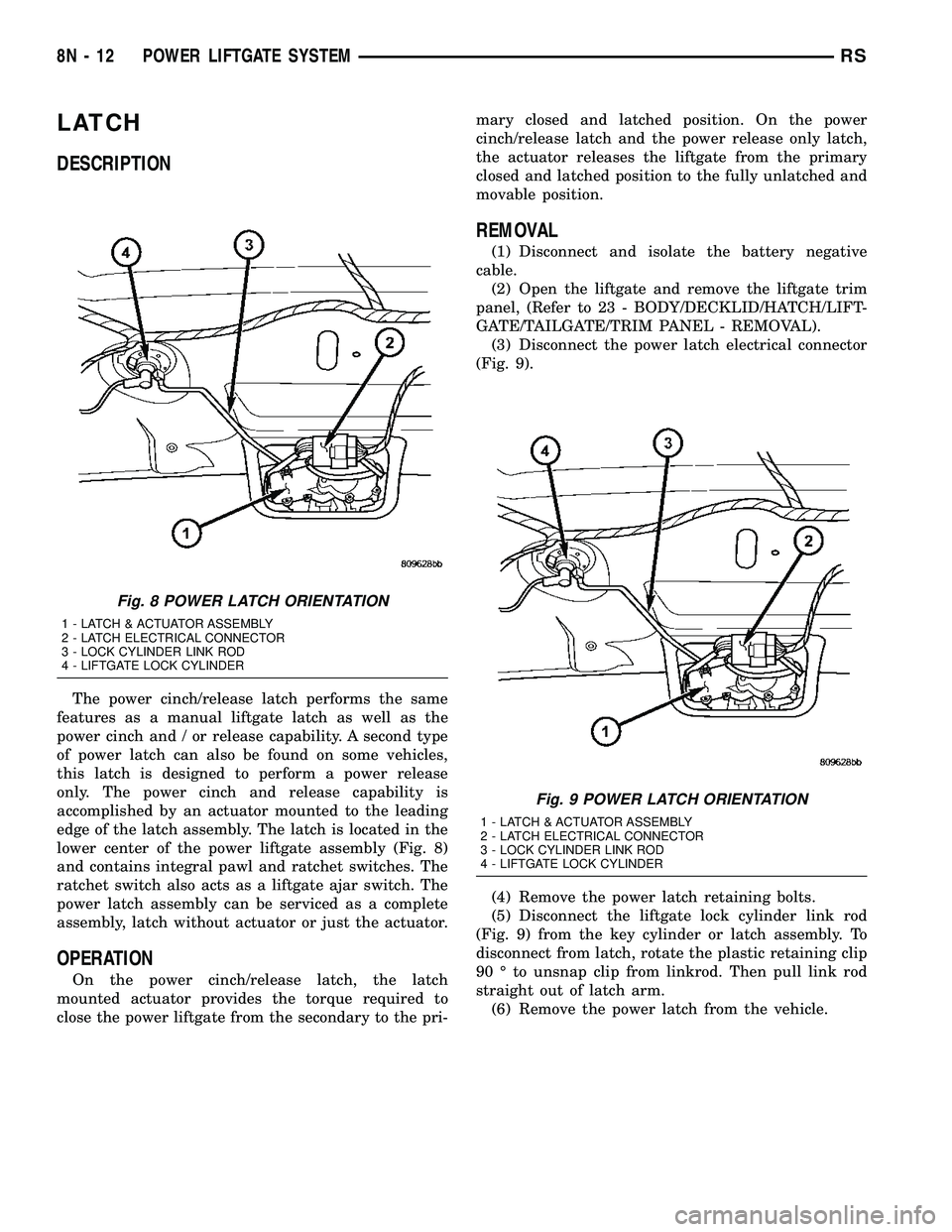
lower center of the power liftgate assembly (Fig. 8)
and contains integral pawl and ratchet switches. The
ratchet switch also acts as a liftgate ajar switch. The
power latch assembly can be serviced as a complete
assembly, latch without actuator or just the actuator.
OPERATION
On the power cinch/release latch, the latch
mounted actuator provides the torque required to
close the power liftgate from the secondary to the pri-mary closed and latched position. On the power
cinch/release latch and the power release only latch,
the actuator releases the liftgate from the primary
closed and latched position to the fully unlatched and
movable position.
REMOVAL
(1) Disconnect and isolate the battery negative
cable.
(2) Open the liftgate and remove the liftgate trim
panel, (Refer to 23 - BODY/DECKLID/HATCH/LIFT-
GATE/TAILGATE/TRIM PANEL - REMOVAL).
(3) Disconnect the power latch electrical connector
(Fig. 9).
(4) Remove the power latch retaining bolts.
(5) Disconnect the liftgate lock cylinder link rod
(Fig. 9) from the key cylinder or latch assembly. To
disconnect from latch, rotate the plastic retaining clip
90 É to unsnap clip from linkrod. Then pull link rod
straight out of latch arm.
(6) Remove the power latch from the vehicle.
Fig. 8 POWER LATCH ORIENTATION
1 - LATCH & ACTUATOR ASSEMBLY
2 - LATCH ELECTRICAL CONNECTOR
3 - LOCK CYLINDER LINK ROD
4 - LIFTGATE LOCK CYLINDER
Fig. 9 POWER LATCH ORIENTATION
1 - LATCH & ACTUATOR ASSEMBLY
2 - LATCH ELECTRICAL CONNECTOR
3 - LOCK CYLINDER LINK ROD
4 - LIFTGATE LOCK CYLINDER
8N - 12 POWER LIFTGATE SYSTEMRS
Page 436 of 2339
INSTALLATION
(1) Position the power latch in the vehicle.
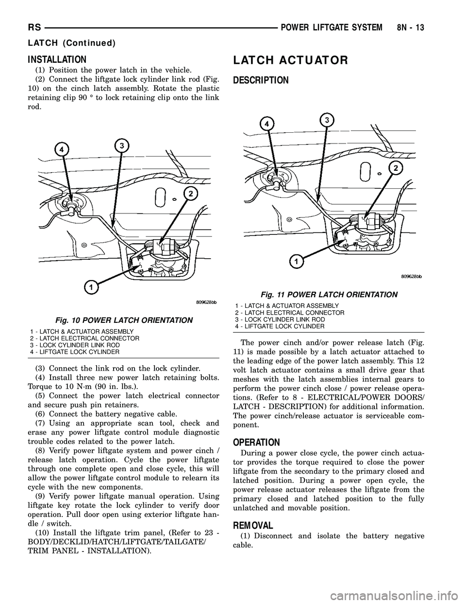
(2) Connect the liftgate lock cylinder link rod (Fig.
10) on the cinch latch assembly. Rotate the plastic
retaining clip 90 É to lock retaining clip onto the link
rod.
(3) Connect the link rod on the lock cylinder.
(4) Install three new power latch retaining bolts.
Torque to 10 N´m (90 in. lbs.).
(5) Connect the power latch electrical connector
and secure push pin retainers.
(6) Connect the battery negative cable.
(7) Using an appropriate scan tool, check and
erase any power liftgate control module diagnostic
trouble codes related to the power latch.
(8) Verify power liftgate system and power cinch /
release latch operation. Cycle the power liftgate
through one complete open and close cycle, this will
allow the power liftgate control module to relearn its
cycle with the new components.
(9) Verify power liftgate manual operation. Using
liftgate key rotate the lock cylinder to verify door
operation. Pull door open using exterior liftgate han-
dle / switch.
(10) Install the liftgate trim panel, (Refer to 23 -
BODY/DECKLID/HATCH/LIFTGATE/TAILGATE/
TRIM PANEL - INSTALLATION).
LATCH ACTUATOR
DESCRIPTION
The power cinch and/or power release latch (Fig.
11) is made possible by a latch actuator attached to
the leading edge of the power latch assembly. This 12
volt latch actuator contains a small drive gear that
meshes with the latch assemblies internal gears to
perform the power cinch close / power release opera-
tions. (Refer to 8 - ELECTRICAL/POWER DOORS/
LATCH - DESCRIPTION) for additional information.
The power cinch/release actuator is serviceable com-
ponent.
OPERATION
During a power close cycle, the power cinch actua-
tor provides the torque required to close the power
liftgate from the secondary to the primary closed and
latched position. During a power open cycle, the
power release actuator releases the liftgate from the
primary closed and latched position to the fully
unlatched and movable position.
REMOVAL
(1) Disconnect and isolate the battery negative
cable.
Fig. 10 POWER LATCH ORIENTATION
1 - LATCH & ACTUATOR ASSEMBLY
2 - LATCH ELECTRICAL CONNECTOR
3 - LOCK CYLINDER LINK ROD
4 - LIFTGATE LOCK CYLINDER
Fig. 11 POWER LATCH ORIENTATION
1 - LATCH & ACTUATOR ASSEMBLY
2 - LATCH ELECTRICAL CONNECTOR
3 - LOCK CYLINDER LINK ROD
4 - LIFTGATE LOCK CYLINDER
RSPOWER LIFTGATE SYSTEM8N-13
LATCH (Continued)
Page 437 of 2339
(2) Open the liftgate and remove the lower liftgate
trim panel. (Refer to 23 - BODY/DECKLID/HATCH/
LIFTGATE/TAILGATE/TRIM PANEL - REMOVAL).
(3) Disconnect the power latch electrical connector
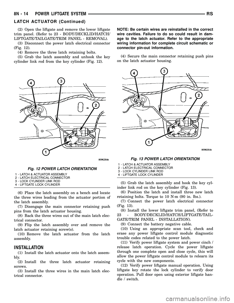
(Fig. 12).
(4) Remove the three latch retaining bolts.
(5) Grab the latch assembly and unhook the key
cylinder link rod from the key cylinder (Fig. 12).
(6) Place the latch assembly on a bench and locate
the three wires leading from the actuator portion of
the latch assembly.
(7) Disengage the main connector retaining push
pins from the latch actuator housing.
(8) Back the three wires out of the main latch elec-
trical connector.
(9) Flip the latch assembly over and remove the
latch actuator retaining screw(s).
(10) Remove the latch actuator from the latch
assembly.
INSTALLATION
(1) Install the latch actuator onto the latch assem-
bly.
(2) Install the three latch actuator retaining
screws.
(3) Install the three wires in the main latch elec-
trical connector.NOTE: Be certain wires are reinstalled in the correct
wire cavities. Failure to do so could result in dam-
age to the latch actuator. Refer to the appropriate
wiring information for complete circuit schematic or
connector pin-out information.
(4) Secure the main connector retaining push pins
on the latch actuator housing.
(5) Grab the latch assembly and hook the key cyl-
inder link rod on the key cylinder (Fig. 13).
(6) Position the latch and install three new latch
retaining bolts. Torque to 10 N´m (90 in. lbs.).
(7) Connect the power latch electrical connector
(Fig. 13).
(8) Install the lower liftgate trim panel, (Refer to
23 - BODY/DECKLID/HATCH/LIFTGATE/TAIL-
GATE/TRIM PANEL - INSTALLATION).
(9) Connect the battery negative cable.
(10) Using an appropriate scan tool, check and
erase any power liftgate control module diagnostic
trouble codes related to the power latch.
(11) Verify power liftgate system and power cinch /
release latch operation. Cycle the power liftgate
through one complete open and close cycle, this will
allow the power liftgate control module to relearn its
cycle with the new components.
(12) Verify power liftgate manual operation. Using
liftgate key rotate the lock cylinder to verify door
operation. Pull door open using exterior liftgate han-
dle / switch.
Fig. 12 POWER LATCH ORIENTATION
1 - LATCH & ACTUATOR ASSEMBLY
2 - LATCH ELECTRICAL CONNECTOR
3 - LOCK CYLINDER LINK ROD
4 - LIFTGATE LOCK CYLINDER
Fig. 13 POWER LATCH ORIENTATION
1 - LATCH & ACTUATOR ASSEMBLY
2 - LATCH ELECTRICAL CONNECTOR
3 - LOCK CYLINDER LINK ROD
4 - LIFTGATE LOCK CYLINDER
8N - 14 POWER LIFTGATE SYSTEMRS
LATCH ACTUATOR (Continued)
Page 438 of 2339
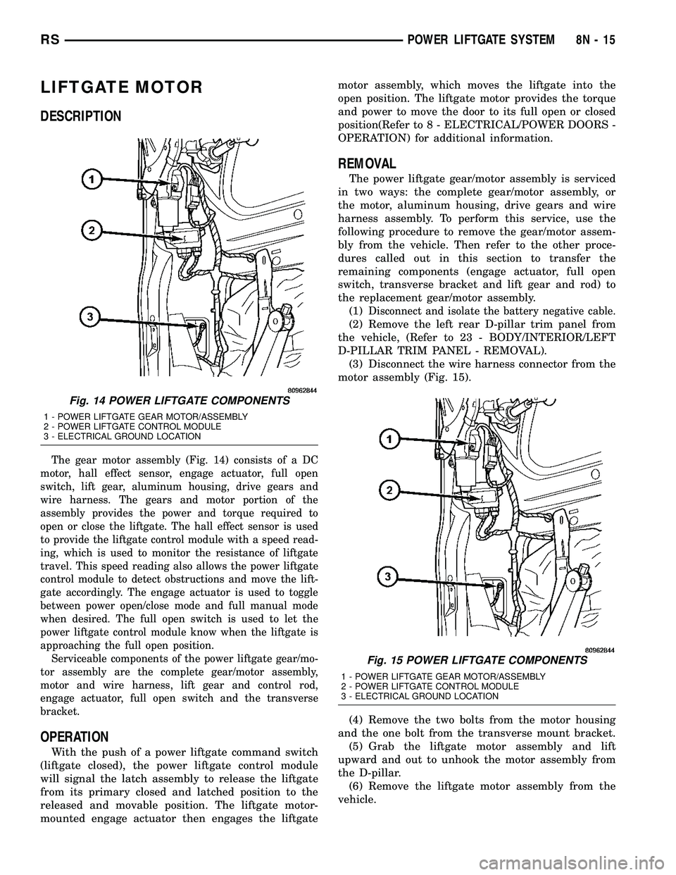
LIFTGATE MOTOR
DESCRIPTION
The gear motor assembly (Fig. 14) consists of a DC
motor, hall effect sensor, engage actuator, full open
switch, lift gear, aluminum housing, drive gears and
wire harness. The gears and motor portion of the
assembly provides the power and torque required to
open or close the liftgate. The hall effect sensor is used
to provide the liftgate control module with a speed read-
ing, which is used to monitor the resistance of liftgate
travel. This speed reading also allows the power liftgate
control module to detect obstructions and move the lift-
gate accordingly. The engage actuator is used to toggle
between power open/close mode and full manual mode
when desired. The full open switch is used to let the
power liftgate control module know when the liftgate is
approaching the full open position.
Serviceable components of the power liftgate gear/mo-
tor assembly are the complete gear/motor assembly,
motor and wire harness, lift gear and control rod,
engage actuator, full open switch and the transverse
bracket.
OPERATION
With the push of a power liftgate command switch
(liftgate closed), the power liftgate control module
will signal the latch assembly to release the liftgate
from its primary closed and latched position to the
released and movable position. The liftgate motor-
mounted engage actuator then engages the liftgatemotor assembly, which moves the liftgate into the
open position. The liftgate motor provides the torque
and power to move the door to its full open or closed
position(Refer to 8 - ELECTRICAL/POWER DOORS -
OPERATION) for additional information.
REMOVAL
The power liftgate gear/motor assembly is serviced
in two ways: the complete gear/motor assembly, or
the motor, aluminum housing, drive gears and wire
harness assembly. To perform this service, use the
following procedure to remove the gear/motor assem-
bly from the vehicle. Then refer to the other proce-
dures called out in this section to transfer the
remaining components (engage actuator, full open
switch, transverse bracket and lift gear and rod) to
the replacement gear/motor assembly.
(1)
Disconnect and isolate the battery negative cable.
(2) Remove the left rear D-pillar trim panel from
the vehicle, (Refer to 23 - BODY/INTERIOR/LEFT
D-PILLAR TRIM PANEL - REMOVAL).
(3) Disconnect the wire harness connector from the
motor assembly (Fig. 15).
(4) Remove the two bolts from the motor housing
and the one bolt from the transverse mount bracket.
(5) Grab the liftgate motor assembly and lift
upward and out to unhook the motor assembly from
the D-pillar.
(6) Remove the liftgate motor assembly from the
vehicle.
Fig. 14 POWER LIFTGATE COMPONENTS
1 - POWER LIFTGATE GEAR MOTOR/ASSEMBLY
2 - POWER LIFTGATE CONTROL MODULE
3 - ELECTRICAL GROUND LOCATION
Fig. 15 POWER LIFTGATE COMPONENTS
1 - POWER LIFTGATE GEAR MOTOR/ASSEMBLY
2 - POWER LIFTGATE CONTROL MODULE
3 - ELECTRICAL GROUND LOCATION
RSPOWER LIFTGATE SYSTEM8N-15
Page 439 of 2339

INSTALLATION
(1) Using the motor housing tab, hook the liftgate
motor assembly on the D-pillar.
(2) Install the three motor assembly retaining
bolts. Torque the two rear most bolts first to 9.5 N´m
(85 in. lbs.). Torque the remaining bolt next to the
window actuator to 9.5 N´m (85 in. lbs.).
(3) Connect the liftgate motor assembly electrical
connector.
(4) Install the D-pillar trim panel on the vehicle,
(Refer to 23 - BODY/INTERIOR/LEFT D-PILLAR
TRIM PANEL - INSTALLATION).
(5) Connect the battery negative cable.
(6) Using an appropriate scan tool, check any
erase any power liftgate control module diagnostic
trouble codes related to the door motor assembly.
(7) Verify power liftgate system operation. Cycle
the power liftgate through one complete open and
close cycle, this will allow the power liftgate control
module to relearn its cycle with the new components.
LIFT GEAR & LINK ROD
DESCRIPTION
The lift gear and rod assembly are located in the
left rear of the vehicle and are visible without remov-ing the D-pillar trim (Fig. 16). The lift gear provides
the leverage to move the liftgate from the closed to
the open position. The lift gear attaches to a bearing
on the gear motor assembly with four bolts. On the
outboard side of the lift gear are riveted on teeth,
which mesh with the gear motor assembly drive
gears during a open or close operation. The rod
assembly is a steel shaft, equipped with two spheri-
cal rod ends which attaches the lift gear to the lift-
gate. The lift gear and rod assembly are serviceable
components.
OPERATION
One end of the rod assembly is attached to the lift-
gate, the other attached to the lift gear. When the lift
gear is driven by the gear motor assembly the lift-
gate is moved to the open or closed position.
REMOVAL
(1) Disconnect and isolate the battery negative
cable.
(2) Remove the left rear D-pillar trim panel from
the vehicle, (Refer to 23 - BODY/INTERIOR/LEFT
D-PILLAR TRIM PANEL - REMOVAL).
(3) Remove the lift gear retaining bolts (Fig. 17).
(4) Remove the lift gear and rod from the vehicle.
Fig. 16 LIFTGATE GEAR/MOTOR ASSEMBLY
1 - TRANSVERSE BRACKET
2 - ENGAGE ACTUATOR
3 - LIFT GEAR AND ROD ASSEMBLY
4 - LIFTGATE MOTOR
Fig. 17 LIFTGATE GEAR MOTOR ASSEMBLY
1 - ENGAGE ACTUATOR RETAINING SCREWS
2 - LIFT GEAR RETAINING BOLTS
8N - 16 POWER LIFTGATE SYSTEMRS
LIFTGATE MOTOR (Continued)
Page 440 of 2339

INSTALLATION
(1) Position the lift gear and rod assembly and
install the retaining bolts (Fig. 18). Torque the bolts
to 8 N´m (71 in. lbs.).
(2) Install the D-pillar trim panel on the vehicle,
(Refer to 23 - BODY/INTERIOR/LEFT D-PILLAR
TRIM PANEL - INSTALLATION).
(3) Connect the battery negative cable.
(4) Using an appropriate scan tool, check any
erase any power liftgate control module diagnostic
trouble codes related to the door motor assembly.
(5) Verify power liftgate system operation. Cycle
the power liftgate through one complete open and
close cycle, this will allow the power liftgate control
module to relearn its cycle with the new components.
CAUTION: Torque link rod to liftgate attachment
bolt to 250 in. lbs. Care must be taken not to over-
torque link rod bolt.
PINCH SENSOR
DESCRIPTION
Pinch sensors are located on each side of the lift-
gate (Fig. 19). These sensors look like weather-strips,
however they consist of pieces of electrically conduc-
tive rubber (tapeswitch), wires, resistor, double sided
tape, and a plastic carrier. They are used to indicate
an obstruction during a power liftgate close cycle.
OPERATION
During a power liftgate close cycle, if either of the
two conductive rubber strips (tapeswitch) of the
pinch sensor come in contact with an obstacle, the
pinch sensor circuit is completed. This tells the
power liftgate control module that a obstruction is
felt. The control module will stop the liftgate imme-
diately and return it to the full open position.
Fig. 18 LIFTGATE GEAR MOTOR ASSEMBLY
1 - ENGAGE ACTUATOR RETAINING SCREWS
2 - LIFT GEAR RETAINING BOLTS
Fig. 19 PINCH SENSOR LOCATION
1 - LIFTGATE
2 - PINCH SENSOR ASSEMBLY
3 - LIFTGATE PROP ROD
4 - PINCH SENSOR WIRE HARNESS CONNECTOR
5 - PINCH SENSOR WIRE HARNESS
RSPOWER LIFTGATE SYSTEM8N-17
LIFT GEAR & LINK ROD (Continued)