door lock CHRYSLER VOYAGER 2005 Service Manual
[x] Cancel search | Manufacturer: CHRYSLER, Model Year: 2005, Model line: VOYAGER, Model: CHRYSLER VOYAGER 2005Pages: 2339, PDF Size: 59.69 MB
Page 16 of 2339
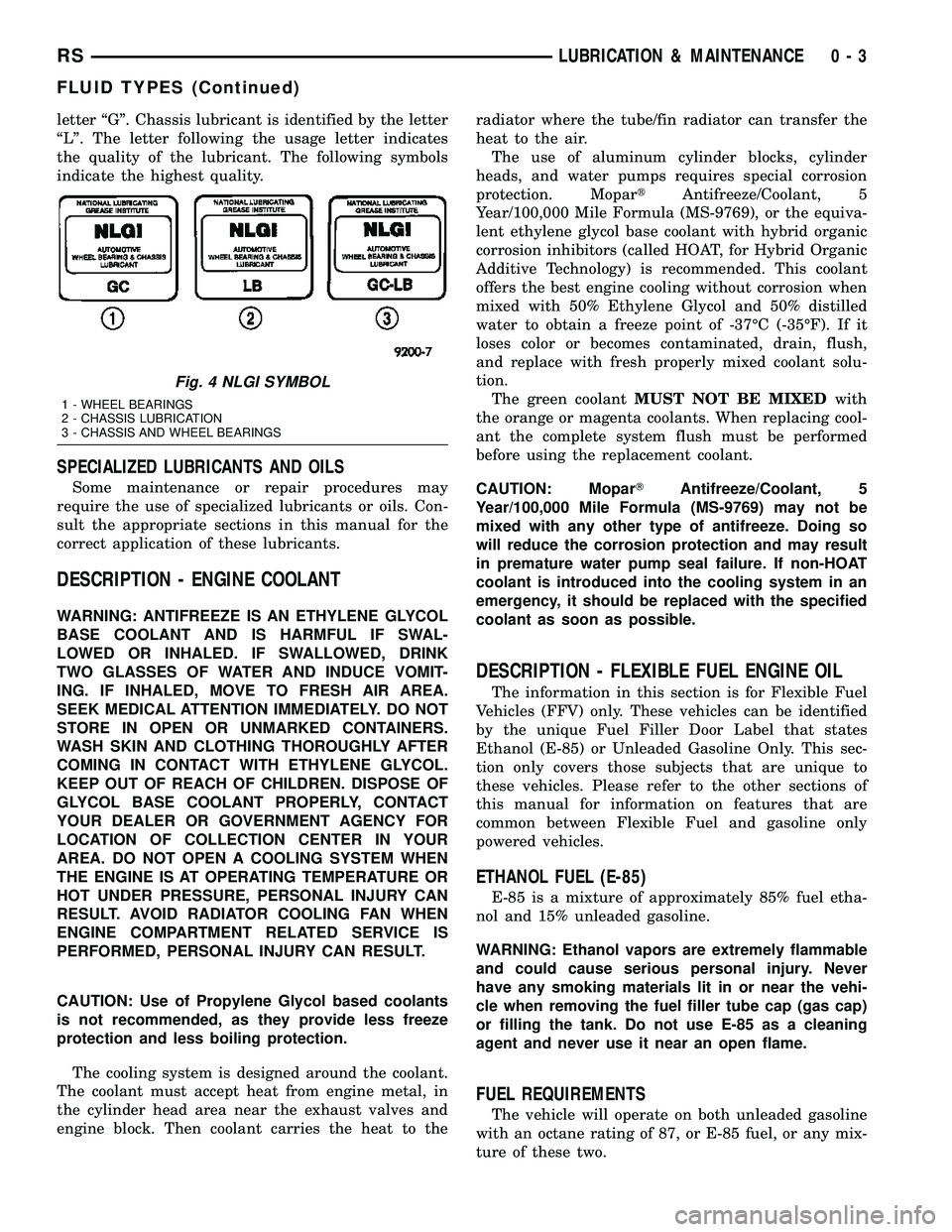
letter ªGº. Chassis lubricant is identified by the letter
ªLº. The letter following the usage letter indicates
the quality of the lubricant. The following symbols
indicate the highest quality.
SPECIALIZED LUBRICANTS AND OILS
Some maintenance or repair procedures may
require the use of specialized lubricants or oils. Con-
sult the appropriate sections in this manual for the
correct application of these lubricants.
DESCRIPTION - ENGINE COOLANT
WARNING: ANTIFREEZE IS AN ETHYLENE GLYCOL
BASE COOLANT AND IS HARMFUL IF SWAL-
LOWED OR INHALED. IF SWALLOWED, DRINK
TWO GLASSES OF WATER AND INDUCE VOMIT-
ING. IF INHALED, MOVE TO FRESH AIR AREA.
SEEK MEDICAL ATTENTION IMMEDIATELY. DO NOT
STORE IN OPEN OR UNMARKED CONTAINERS.
WASH SKIN AND CLOTHING THOROUGHLY AFTER
COMING IN CONTACT WITH ETHYLENE GLYCOL.
KEEP OUT OF REACH OF CHILDREN. DISPOSE OF
GLYCOL BASE COOLANT PROPERLY, CONTACT
YOUR DEALER OR GOVERNMENT AGENCY FOR
LOCATION OF COLLECTION CENTER IN YOUR
AREA. DO NOT OPEN A COOLING SYSTEM WHEN
THE ENGINE IS AT OPERATING TEMPERATURE OR
HOT UNDER PRESSURE, PERSONAL INJURY CAN
RESULT. AVOID RADIATOR COOLING FAN WHEN
ENGINE COMPARTMENT RELATED SERVICE IS
PERFORMED, PERSONAL INJURY CAN RESULT.
CAUTION: Use of Propylene Glycol based coolants
is not recommended, as they provide less freeze
protection and less boiling protection.
The cooling system is designed around the coolant.
The coolant must accept heat from engine metal, in
the cylinder head area near the exhaust valves and
engine block. Then coolant carries the heat to theradiator where the tube/fin radiator can transfer the
heat to the air.
The use of aluminum cylinder blocks, cylinder
heads, and water pumps requires special corrosion
protection. MopartAntifreeze/Coolant, 5
Year/100,000 Mile Formula (MS-9769), or the equiva-
lent ethylene glycol base coolant with hybrid organic
corrosion inhibitors (called HOAT, for Hybrid Organic
Additive Technology) is recommended. This coolant
offers the best engine cooling without corrosion when
mixed with 50% Ethylene Glycol and 50% distilled
water to obtain a freeze point of -37ÉC (-35ÉF). If it
loses color or becomes contaminated, drain, flush,
and replace with fresh properly mixed coolant solu-
tion.
The green coolantMUST NOT BE MIXEDwith
the orange or magenta coolants. When replacing cool-
ant the complete system flush must be performed
before using the replacement coolant.
CAUTION: MoparTAntifreeze/Coolant, 5
Year/100,000 Mile Formula (MS-9769) may not be
mixed with any other type of antifreeze. Doing so
will reduce the corrosion protection and may result
in premature water pump seal failure. If non-HOAT
coolant is introduced into the cooling system in an
emergency, it should be replaced with the specified
coolant as soon as possible.
DESCRIPTION - FLEXIBLE FUEL ENGINE OIL
The information in this section is for Flexible Fuel
Vehicles (FFV) only. These vehicles can be identified
by the unique Fuel Filler Door Label that states
Ethanol (E-85) or Unleaded Gasoline Only. This sec-
tion only covers those subjects that are unique to
these vehicles. Please refer to the other sections of
this manual for information on features that are
common between Flexible Fuel and gasoline only
powered vehicles.
ETHANOL FUEL (E-85)
E-85 is a mixture of approximately 85% fuel etha-
nol and 15% unleaded gasoline.
WARNING: Ethanol vapors are extremely flammable
and could cause serious personal injury. Never
have any smoking materials lit in or near the vehi-
cle when removing the fuel filler tube cap (gas cap)
or filling the tank. Do not use E-85 as a cleaning
agent and never use it near an open flame.
FUEL REQUIREMENTS
The vehicle will operate on both unleaded gasoline
with an octane rating of 87, or E-85 fuel, or any mix-
ture of these two.
Fig. 4 NLGI SYMBOL
1 - WHEEL BEARINGS
2 - CHASSIS LUBRICATION
3 - CHASSIS AND WHEEL BEARINGS
RSLUBRICATION & MAINTENANCE0-3
FLUID TYPES (Continued)
Page 177 of 2339
CABLE - PARKING BRAKE
FRONT
REMOVAL
REMOVAL
(1) Raise and support the vehicle. (Refer to
LUBRICATION & MAINTENANCE/HOISTING -
STANDARD PROCEDURE).
(2) Manually release the automatic self-adjusting
mechanism tension of the parking brake lever (pedal)
assembly. (Refer to 5 - BRAKES - STANDARD PRO-
CEDURE).
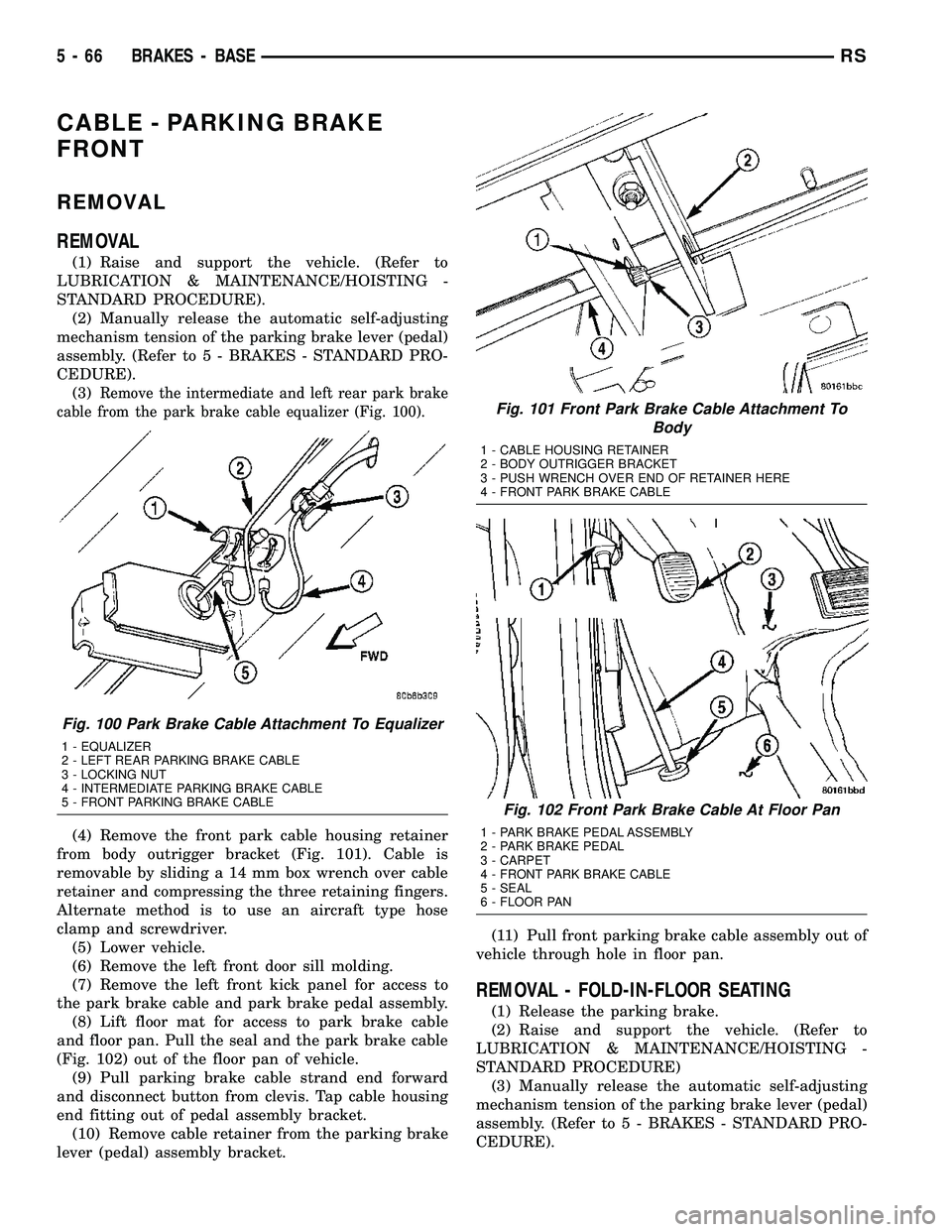
(3)
Remove the intermediate and left rear park brake
cable from the park brake cable equalizer (Fig. 100).
(4) Remove the front park cable housing retainer
from body outrigger bracket (Fig. 101). Cable is
removable by sliding a 14 mm box wrench over cable
retainer and compressing the three retaining fingers.
Alternate method is to use an aircraft type hose
clamp and screwdriver.
(5) Lower vehicle.
(6) Remove the left front door sill molding.
(7) Remove the left front kick panel for access to
the park brake cable and park brake pedal assembly.
(8) Lift floor mat for access to park brake cable
and floor pan. Pull the seal and the park brake cable
(Fig. 102) out of the floor pan of vehicle.
(9) Pull parking brake cable strand end forward
and disconnect button from clevis. Tap cable housing
end fitting out of pedal assembly bracket.
(10) Remove cable retainer from the parking brake
lever (pedal) assembly bracket.(11) Pull front parking brake cable assembly out of
vehicle through hole in floor pan.
REMOVAL - FOLD-IN-FLOOR SEATING
(1) Release the parking brake.
(2) Raise and support the vehicle. (Refer to
LUBRICATION & MAINTENANCE/HOISTING -
STANDARD PROCEDURE)
(3) Manually release the automatic self-adjusting
mechanism tension of the parking brake lever (pedal)
assembly. (Refer to 5 - BRAKES - STANDARD PRO-
CEDURE).
Fig. 100 Park Brake Cable Attachment To Equalizer
1 - EQUALIZER
2 - LEFT REAR PARKING BRAKE CABLE
3 - LOCKING NUT
4 - INTERMEDIATE PARKING BRAKE CABLE
5 - FRONT PARKING BRAKE CABLE
Fig. 101 Front Park Brake Cable Attachment To
Body
1 - CABLE HOUSING RETAINER
2 - BODY OUTRIGGER BRACKET
3 - PUSH WRENCH OVER END OF RETAINER HERE
4 - FRONT PARK BRAKE CABLE
Fig. 102 Front Park Brake Cable At Floor Pan
1 - PARK BRAKE PEDAL ASSEMBLY
2 - PARK BRAKE PEDAL
3 - CARPET
4 - FRONT PARK BRAKE CABLE
5 - SEAL
6 - FLOOR PAN
5 - 66 BRAKES - BASERS
Page 178 of 2339
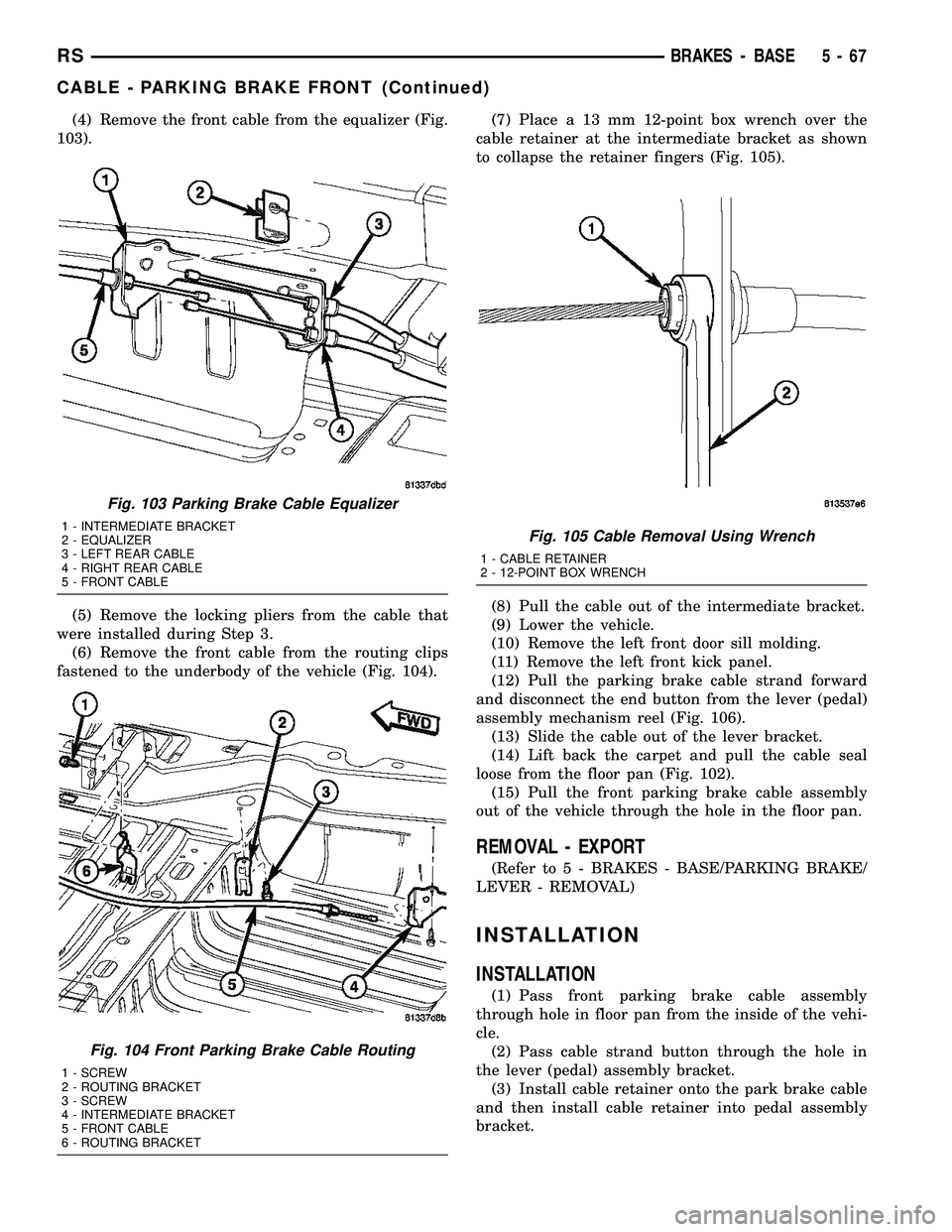
(4) Remove the front cable from the equalizer (Fig.
103).
(5) Remove the locking pliers from the cable that
were installed during Step 3.
(6) Remove the front cable from the routing clips
fastened to the underbody of the vehicle (Fig. 104).(7) Place a 13 mm 12-point box wrench over the
cable retainer at the intermediate bracket as shown
to collapse the retainer fingers (Fig. 105).
(8) Pull the cable out of the intermediate bracket.
(9) Lower the vehicle.
(10) Remove the left front door sill molding.
(11) Remove the left front kick panel.
(12) Pull the parking brake cable strand forward
and disconnect the end button from the lever (pedal)
assembly mechanism reel (Fig. 106).
(13) Slide the cable out of the lever bracket.
(14) Lift back the carpet and pull the cable seal
loose from the floor pan (Fig. 102).
(15) Pull the front parking brake cable assembly
out of the vehicle through the hole in the floor pan.
REMOVAL - EXPORT
(Refer to 5 - BRAKES - BASE/PARKING BRAKE/
LEVER - REMOVAL)
INSTALLATION
INSTALLATION
(1) Pass front parking brake cable assembly
through hole in floor pan from the inside of the vehi-
cle.
(2) Pass cable strand button through the hole in
the lever (pedal) assembly bracket.
(3) Install cable retainer onto the park brake cable
and then install cable retainer into pedal assembly
bracket.
Fig. 103 Parking Brake Cable Equalizer
1 - INTERMEDIATE BRACKET
2 - EQUALIZER
3 - LEFT REAR CABLE
4 - RIGHT REAR CABLE
5 - FRONT CABLE
Fig. 104 Front Parking Brake Cable Routing
1 - SCREW
2 - ROUTING BRACKET
3 - SCREW
4 - INTERMEDIATE BRACKET
5 - FRONT CABLE
6 - ROUTING BRACKET
Fig. 105 Cable Removal Using Wrench
1 - CABLE RETAINER
2 - 12-POINT BOX WRENCH
RSBRAKES - BASE5-67
CABLE - PARKING BRAKE FRONT (Continued)
Page 179 of 2339
(4) Install the end of the park brake cable into the
retainer previously installed into the park brake
pedal bracket.
(5) Install cable strand button into the clevis on
the park brake pedal mechanism.
(6) Install the front park brake cable floor pan seal
into hole in floor pan. Seal is to be installed so the
flange on the seal is flush with the floor pan (Fig.
102). Fold carpeting back down on floor.
(7) Raise vehicle.
(8) Insert brake cable and housing into body out-
rigger bracket making certain that housing retainer
fingers lock the housing firmly into place (Fig. 101).
(9) Manually reset the automatic self-adjusting
mechanism tension of the parking brake lever (pedal)
assembly. (Refer to 5 - BRAKES - STANDARD PRO-
CEDURE).
(10) Assemble the park brake cables onto the park
brake cable equalizer (Fig. 100).
(11) Lower vehicle and apply the park brake pedal
1 time. This will seat the parking brake cables.
INSTALLATION - FOLD-IN-FLOOR SEATING
(1) Pass most of the front parking brake cable
assembly down through hole in the floor pan from
inside the vehicle.
(2) Pass the lever-end cable strand button through
the hole in the lever (pedal) assembly bracket.
(3) Install the end of the cable housing into the
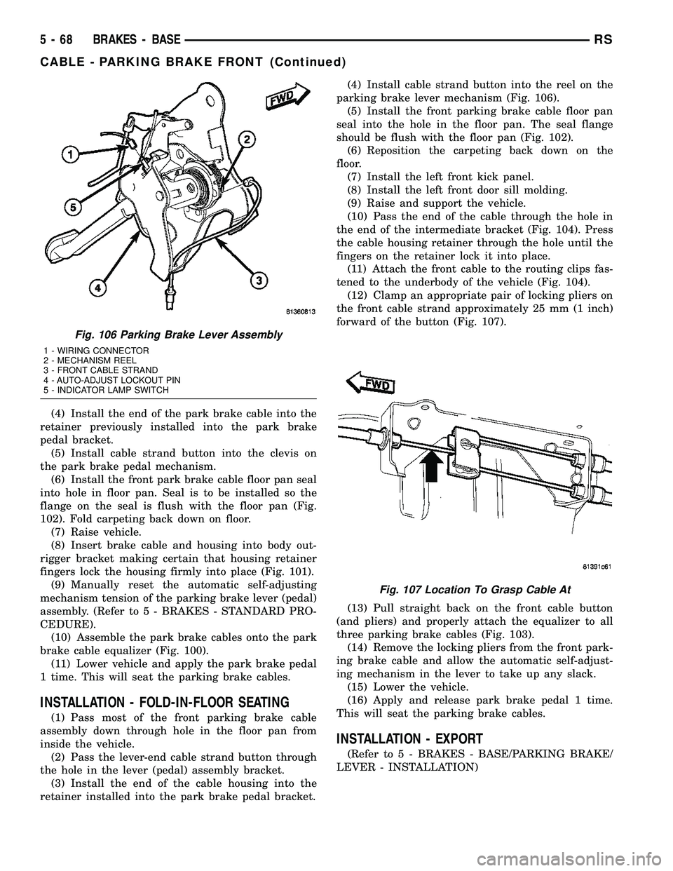
retainer installed into the park brake pedal bracket.(4) Install cable strand button into the reel on the
parking brake lever mechanism (Fig. 106).
(5) Install the front parking brake cable floor pan
seal into the hole in the floor pan. The seal flange
should be flush with the floor pan (Fig. 102).
(6) Reposition the carpeting back down on the
floor.
(7) Install the left front kick panel.
(8) Install the left front door sill molding.
(9) Raise and support the vehicle.
(10) Pass the end of the cable through the hole in
the end of the intermediate bracket (Fig. 104). Press
the cable housing retainer through the hole until the
fingers on the retainer lock it into place.
(11) Attach the front cable to the routing clips fas-
tened to the underbody of the vehicle (Fig. 104).
(12) Clamp an appropriate pair of locking pliers on
the front cable strand approximately 25 mm (1 inch)
forward of the button (Fig. 107).
(13) Pull straight back on the front cable button
(and pliers) and properly attach the equalizer to all
three parking brake cables (Fig. 103).
(14) Remove the locking pliers from the front park-
ing brake cable and allow the automatic self-adjust-
ing mechanism in the lever to take up any slack.
(15) Lower the vehicle.
(16) Apply and release park brake pedal 1 time.
This will seat the parking brake cables.
INSTALLATION - EXPORT
(Refer to 5 - BRAKES - BASE/PARKING BRAKE/
LEVER - INSTALLATION)
Fig. 106 Parking Brake Lever Assembly
1 - WIRING CONNECTOR
2 - MECHANISM REEL
3 - FRONT CABLE STRAND
4 - AUTO-ADJUST LOCKOUT PIN
5 - INDICATOR LAMP SWITCH
Fig. 107 Location To Grasp Cable At
5 - 68 BRAKES - BASERS
CABLE - PARKING BRAKE FRONT (Continued)
Page 186 of 2339
INSTALLATION - LEFT REAR
(1) Install the rear parking brake cable in the
brake support plate. Insert cable housing retainer
into brake support plate making certain that cable
housing retainer fingers lock the housing and
retainer firmly into place.
(2) Attach the parking brake cable onto the park
brake actuator lever.
(3) Install the brake shoes on the rear brake sup-
port plate. (Refer to 5 - BRAKES/HYDRAULIC/ME-
CHANICAL/BRAKE PADS/SHOES -
INSTALLATION).
(4) Insert cable housing retainer into body outrig-
ger bracket making certain that cable housing
retainer fingers lock the housing firmly into place.
(5) Connect rear parking brake cable to the equal-
izer bracket (Fig. 115).
(6) Install brake drum, and wheel and tire assem-
bly.
(7) Remove the locking pliers from the front park
brake cable. This will automatically adjust the park
brake cables.
(8) Apply and release park brake pedal 1 time.
This will seat the park brake cables.
INSTALLATION - FOLD-IN-FLOOR SEATING
(1) Pass the leading end of the rear parking brake
cable through the hole in the end of the intermediate
bracket (Fig. 123). Press the cable housing retainer
through the hole until the fingers on the retainer
lock it into place.
(2) Route the cable back toward the brake assem-
bly placing it in the routing clip fastened to the
underbody of the vehicle (Fig. 119). Make sure to
stay to the inside of the left stabilizer bar link while
routing either cable.
(3) If the right rear cable is being serviced, install
screws, attaching the cable routing clamps to the
rear axle (Fig. 120).
(4) Pass the cable through the hole in the brake
adapter and hook the cable eyelet to the shoe lever
(Fig. 121).
(5) Install the screw fastening the cable to the rear
brake adapter (Fig. 121).
(6) Pull straight back on the front cable button
(and pliers) and properly attach the equalizer to all
three parking brake cables (Fig. 118).
(7) Remove the locking pliers from the front park-
ing brake cable and allow the automatic self-adjust-
ing mechanism in the lever to take up any slack.
(8) Lower the vehicle.
(9) Apply and release park brake pedal 1 time.
This will seat the parking brake cables.
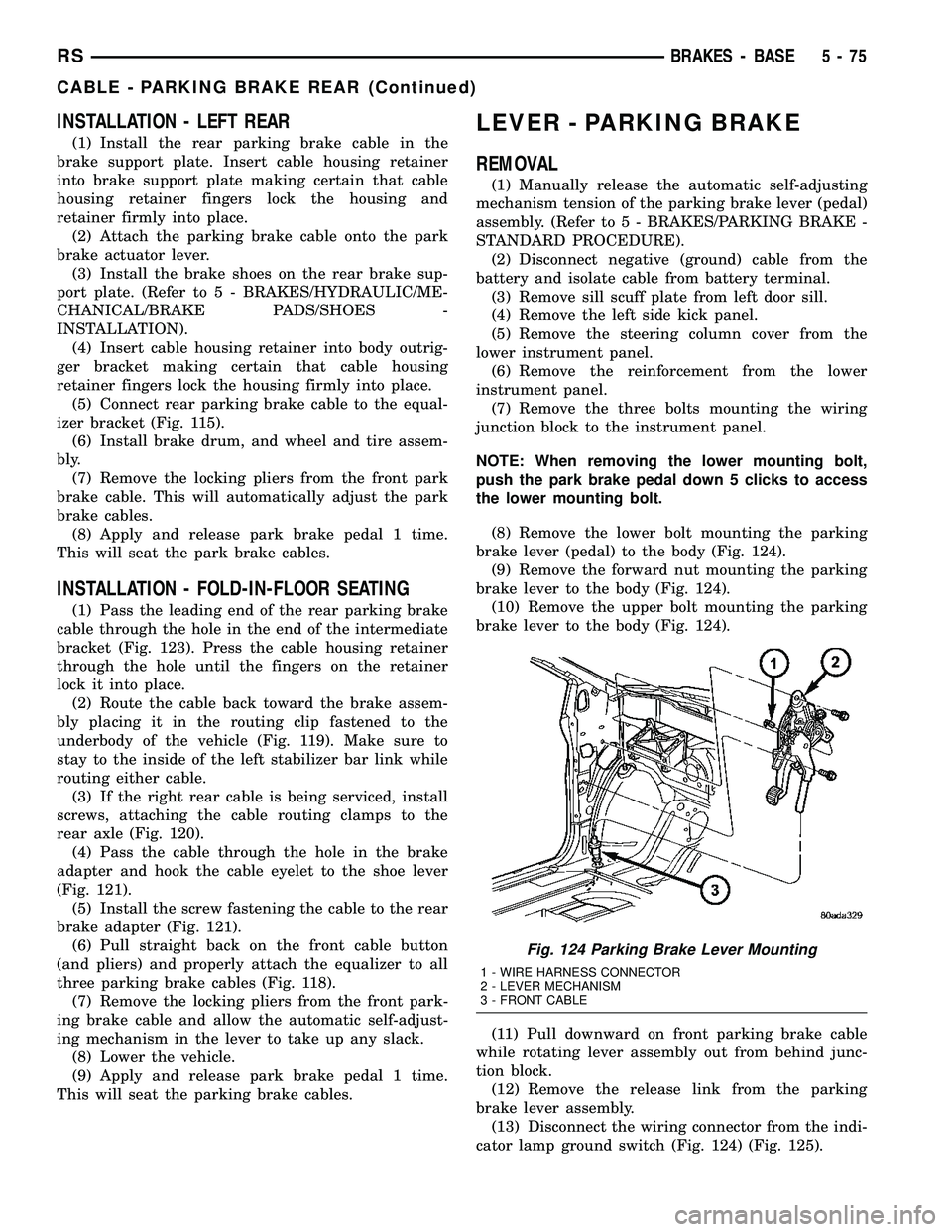
LEVER - PARKING BRAKE
REMOVAL
(1) Manually release the automatic self-adjusting
mechanism tension of the parking brake lever (pedal)
assembly. (Refer to 5 - BRAKES/PARKING BRAKE -
STANDARD PROCEDURE).
(2) Disconnect negative (ground) cable from the
battery and isolate cable from battery terminal.
(3) Remove sill scuff plate from left door sill.
(4) Remove the left side kick panel.
(5) Remove the steering column cover from the
lower instrument panel.
(6) Remove the reinforcement from the lower
instrument panel.
(7) Remove the three bolts mounting the wiring
junction block to the instrument panel.
NOTE: When removing the lower mounting bolt,
push the park brake pedal down 5 clicks to access
the lower mounting bolt.
(8) Remove the lower bolt mounting the parking
brake lever (pedal) to the body (Fig. 124).
(9) Remove the forward nut mounting the parking
brake lever to the body (Fig. 124).
(10) Remove the upper bolt mounting the parking
brake lever to the body (Fig. 124).
(11) Pull downward on front parking brake cable
while rotating lever assembly out from behind junc-
tion block.
(12) Remove the release link from the parking
brake lever assembly.
(13) Disconnect the wiring connector from the indi-
cator lamp ground switch (Fig. 124) (Fig. 125).
Fig. 124 Parking Brake Lever Mounting
1 - WIRE HARNESS CONNECTOR
2 - LEVER MECHANISM
3 - FRONT CABLE
RSBRAKES - BASE5-75
CABLE - PARKING BRAKE REAR (Continued)
Page 187 of 2339
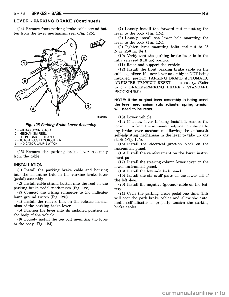
(14) Remove front parking brake cable strand but-
ton from the lever mechanism reel (Fig. 125).
(15) Remove the parking brake lever assembly
from the cable.
INSTALLATION
(1) Install the parking brake cable end housing
into the mounting hole in the parking brake lever
(pedal) assembly.
(2) Install cable strand button into the reel on the
parking brake pedal mechanism (Fig. 125).
(3) Connect the wiring connector to the indicator
lamp ground switch (Fig. 125).
(4) Install the release link on the release mecha-
nism of the parking brake lever.
(5) Position the lever into its installed position on
the body of the vehicle.
(6) Loosely install the top bolt mounting the lever
to the body (Fig. 124).(7) Loosely install the forward nut mounting the
lever to the body (Fig. 124).
(8) Loosely install the lower bolt mounting the
lever to the body (Fig. 124).
(9) Tighten lever mounting bolts and nut to 28
N´m (250 in. lbs.).
(10) Verify that the parking brake lever is in the
fully released (full up) position.
(11) Raise and support the vehicle.
(12) Install the front parking brake cable on the
cable equalizer. If a new lever assembly is NOT being
installed, perform PARKING BRAKE AUTOMATIC
ADJUSTER TENSION RESET as necessary. (Refer
to 5 - BRAKES/PARKING BRAKE - STANDARD
PROCEDURE)
NOTE: If the original lever assembly is being used,
the lever mechanism auto adjuster spring tension
will need to be reset.
(13) Lower vehicle.
(14) If a new lever is being installed, remove the
lockout pin from the automatic adjuster on the park-
ing brake lever mechanism allowing the automatic
self-adjusting mechanism in the lever to take up any
slack (Fig. 125).
(15) Install the electrical junction block on the
instrument panel.
(16) Install the reinforcement on the lower instru-
ment panel.
(17) Install the steering column lower cover on the
lower instrument panel.
(18) Install the left side kick panel.
(19) Install the sill scuff plate on the lower sill of
the left door.
(20) Install the negative (ground) cable on the bat-
tery.
(21) Cycle the parking brake pedal one time. This
will seat the park brake cables and allow the auto-
matic self-adjuster to properly tension the parking
brake cables.
Fig. 125 Parking Brake Lever Assembly
1 - WIRING CONNECTOR
2 - MECHANISM REEL
3 - FRONT CABLE STRAND
4 - AUTO-ADJUST LOCKOUT PIN
5 - INDICATOR LAMP SWITCH
5 - 76 BRAKES - BASERS
LEVER - PARKING BRAKE (Continued)
Page 282 of 2339
NO FASTEN SEAT BELT LAMP WHEN IGNITION
SWITCH IS TURNED ON.
(1) Check for burned out lamp.
(2) Using a voltmeter check for voltage at the clus-
ter connector:
(a) Pin 2 of the mechanical instrument cluster
for battery feed.
(b) Pin 11 of the mechanical instrument cluster
for ignition voltage.
(3) Repair as necessary.
FASTEN SEAT BELT LAMP OR TONE CONTINUES
FOR MORE THAN 10 SECONDS AFTER SEAT
BELTS ARE FASTENED AND DRIVER'S DOOR IS
CLOSED.
Refer to the proper Body Diagnostic Procedures
manual.
NO TONE WHEN PARK OR HEADLAMPS ARE ON
AND DRIVER'S DOOR IS OPEN.
Make sure ignition is in lock position with the key
removed.
(1) Check the BCM DTC's and BCM sensors to
verify the door is open. Repair as necessary.
(2) Actuate Chime (BCM actuates).
(3) Inspect BCM connectors and wires for proper
connection.
(4) Measure with a voltmeter the voltage (12v) on
BCM connector (PX2) pin 34 with harness connected.
(5) Check BCM sensors to verify headlamp switch
position.
PARK ASSIST DISPLAY
DESCRIPTION
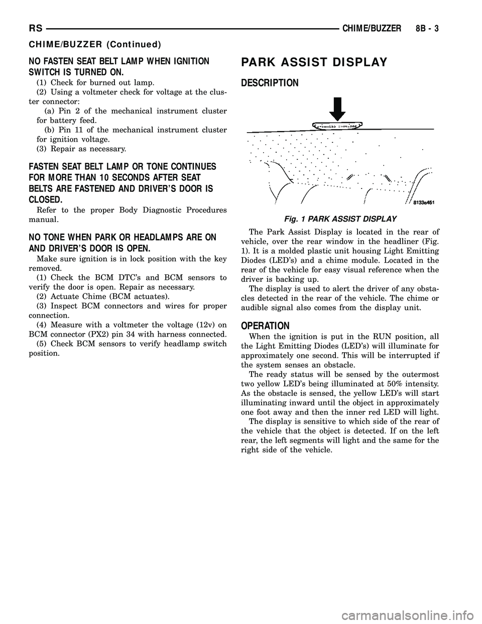
The Park Assist Display is located in the rear of
vehicle, over the rear window in the headliner (Fig.
1). It is a molded plastic unit housing Light Emitting
Diodes (LED's) and a chime module. Located in the
rear of the vehicle for easy visual reference when the
driver is backing up.
The display is used to alert the driver of any obsta-
cles detected in the rear of the vehicle. The chime or
audible signal also comes from the display unit.
OPERATION
When the ignition is put in the RUN position, all
the Light Emitting Diodes (LED's) will illuminate for
approximately one second. This will be interrupted if
the system senses an obstacle.
The ready status will be sensed by the outermost
two yellow LED's being illuminated at 50% intensity.
As the obstacle is sensed, the yellow LED's will start
illuminating inward until the object in approximately
one foot away and then the inner red LED will light.
The display is sensitive to which side of the rear of
the vehicle that the object is detected. If on the left
rear, the left segments will light and the same for the
right side of the vehicle.
Fig. 1 PARK ASSIST DISPLAY
RSCHIME/BUZZER8B-3
CHIME/BUZZER (Continued)
Page 286 of 2339
ELECTRONIC CONTROL MODULES
TABLE OF CONTENTS
page page
ELECTRONIC CONTROL MODULES
STANDARD PROCEDURE - PCM/SKIM
PROGRAMMING.......................1
BODY CONTROL MODULE
DESCRIPTION..........................2
OPERATION............................3
REMOVAL.............................4
INSTALLATION..........................4
CONTROLLER ANTILOCK BRAKE
DESCRIPTION..........................4
OPERATION............................5
REMOVAL.............................5
INSTALLATION..........................6
DATA LINK CONNECTOR
DESCRIPTION..........................6
OPERATION............................6
FRONT CONTROL MODULE
DESCRIPTION..........................7
OPERATION............................7
DIAGNOSIS AND TESTING
FRONT CONTROL MODULE..............7
REMOVAL.............................7
INSTALLATION..........................7
HEATED SEAT MODULE
DESCRIPTION..........................8
OPERATION............................8
DIAGNOSIS AND TESTING
HEATED SEAT MODULE.................9
REMOVAL.............................9
INSTALLATION..........................9
MEMORY SEAT/MIRROR MODULE
DESCRIPTION..........................9
OPERATION............................9
DIAGNOSIS AND TESTING
MEMORY SEAT/MIRROR MODULE.........9
REMOVAL.............................10
INSTALLATION.........................10
POWER LIFTGATE CONTROL MODULE
DESCRIPTION.........................10OPERATION...........................10
DIAGNOSIS AND TESTING
POWER LIFTGATE CONTROL MODULE....10
REMOVAL.............................10
INSTALLATION.........................11
POWERTRAIN CONTROL MODULE
DESCRIPTION
DESCRIPTION........................11
OPERATION - SENSOR RETURN - PCM
INPUT..............................14
OPERATION - DATA BUS COMMUNICATION
RECEIVE - PCM INPUT.................14
OPERATION - IGNITION SENSE - PCM
INPUT..............................14
OPERATION - PCM GROUND............14
OPERATION - 5 VOLT SUPPLY - PCM
OUTPUT............................15
STANDARD PROCEDURE
STANDARD PROCEDURE - OBTAINING
DIAGNOSTIC TROUBLE CODES..........15
STANDARD PROCEDURE - PINION
FACTOR SETTING.....................15
STANDARD PROCEDURE - QUICK LEARN
PROCEDURE........................15
REMOVAL
REMOVAL - SBEC CONTROLLER.........16
REMOVAL - NGC CONTROLLER..........16
INSTALLATION
INSTALLATION - SBEC CONTROLLER.....17
INSTALLATION.......................17
SLIDING DOOR CONTROL MODULE
DESCRIPTION.........................18
OPERATION...........................18
DIAGNOSIS AND TESTING
SLIDING DOOR CONTROL MODULE......18
REMOVAL.............................18
INSTALLATION.........................19
ELECTRONIC CONTROL
MODULES
STANDARD PROCEDURE - PCM/SKIM
PROGRAMMING
NOTE: Before replacing the PCM for a failed driver,
control circuit or ground circuit, be sure to checkthe related component/circuit integrity for failures
not detected due to a double fault in the circuit.
Most PCM driver/control circuit failures are caused
by internal component failures (i.e. relay and sole-
noids) and shorted circuits (i.e. pull-ups, drivers
and switched circuits). These failures are difficult to
detect when a double fault has occurred and only
one DTC has set.
RSELECTRONIC CONTROL MODULES8E-1
Page 288 of 2339
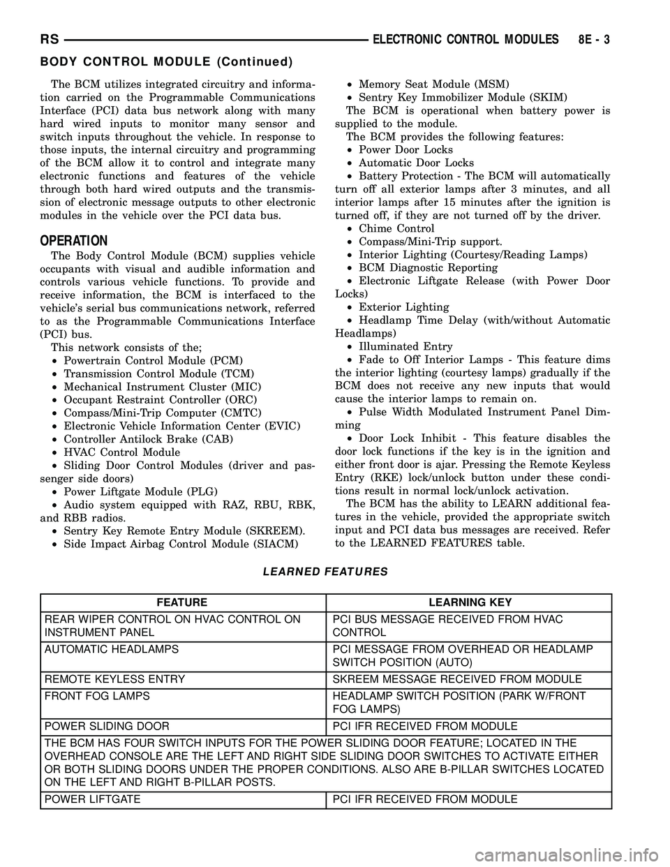
The BCM utilizes integrated circuitry and informa-
tion carried on the Programmable Communications
Interface (PCI) data bus network along with many
hard wired inputs to monitor many sensor and
switch inputs throughout the vehicle. In response to
those inputs, the internal circuitry and programming
of the BCM allow it to control and integrate many
electronic functions and features of the vehicle
through both hard wired outputs and the transmis-
sion of electronic message outputs to other electronic
modules in the vehicle over the PCI data bus.
OPERATION
The Body Control Module (BCM) supplies vehicle
occupants with visual and audible information and
controls various vehicle functions. To provide and
receive information, the BCM is interfaced to the
vehicle's serial bus communications network, referred
to as the Programmable Communications Interface
(PCI) bus.
This network consists of the;
²Powertrain Control Module (PCM)
²Transmission Control Module (TCM)
²Mechanical Instrument Cluster (MIC)
²Occupant Restraint Controller (ORC)
²Compass/Mini-Trip Computer (CMTC)
²Electronic Vehicle Information Center (EVIC)
²Controller Antilock Brake (CAB)
²HVAC Control Module
²Sliding Door Control Modules (driver and pas-
senger side doors)
²Power Liftgate Module (PLG)
²Audio system equipped with RAZ, RBU, RBK,
and RBB radios.
²Sentry Key Remote Entry Module (SKREEM).
²Side Impact Airbag Control Module (SIACM)²Memory Seat Module (MSM)
²Sentry Key Immobilizer Module (SKIM)
The BCM is operational when battery power is
supplied to the module.
The BCM provides the following features:
²Power Door Locks
²Automatic Door Locks
²Battery Protection - The BCM will automatically
turn off all exterior lamps after 3 minutes, and all
interior lamps after 15 minutes after the ignition is
turned off, if they are not turned off by the driver.
²Chime Control
²Compass/Mini-Trip support.
²Interior Lighting (Courtesy/Reading Lamps)
²BCM Diagnostic Reporting
²Electronic Liftgate Release (with Power Door
Locks)
²Exterior Lighting
²Headlamp Time Delay (with/without Automatic
Headlamps)
²Illuminated Entry
²Fade to Off Interior Lamps - This feature dims
the interior lighting (courtesy lamps) gradually if the
BCM does not receive any new inputs that would
cause the interior lamps to remain on.
²Pulse Width Modulated Instrument Panel Dim-
ming
²Door Lock Inhibit - This feature disables the
door lock functions if the key is in the ignition and
either front door is ajar. Pressing the Remote Keyless
Entry (RKE) lock/unlock button under these condi-
tions result in normal lock/unlock activation.
The BCM has the ability to LEARN additional fea-
tures in the vehicle, provided the appropriate switch
input and PCI data bus messages are received. Refer
to the LEARNED FEATURES table.
LEARNED FEATURES
FEATURE LEARNING KEY
REAR WIPER CONTROL ON HVAC CONTROL ON
INSTRUMENT PANELPCI BUS MESSAGE RECEIVED FROM HVAC
CONTROL
AUTOMATIC HEADLAMPS PCI MESSAGE FROM OVERHEAD OR HEADLAMP
SWITCH POSITION (AUTO)
REMOTE KEYLESS ENTRY SKREEM MESSAGE RECEIVED FROM MODULE
FRONT FOG LAMPS HEADLAMP SWITCH POSITION (PARK W/FRONT
FOG LAMPS)
POWER SLIDING DOOR PCI IFR RECEIVED FROM MODULE
THE BCM HAS FOUR SWITCH INPUTS FOR THE POWER SLIDING DOOR FEATURE; LOCATED IN THE
OVERHEAD CONSOLE ARE THE LEFT AND RIGHT SIDE SLIDING DOOR SWITCHES TO ACTIVATE EITHER
OR BOTH SLIDING DOORS UNDER THE PROPER CONDITIONS. ALSO ARE B-PILLAR SWITCHES LOCATED
ON THE LEFT AND RIGHT B-PILLAR POSTS.
POWER LIFTGATE PCI IFR RECEIVED FROM MODULE
RSELECTRONIC CONTROL MODULES8E-3
BODY CONTROL MODULE (Continued)
Page 289 of 2339
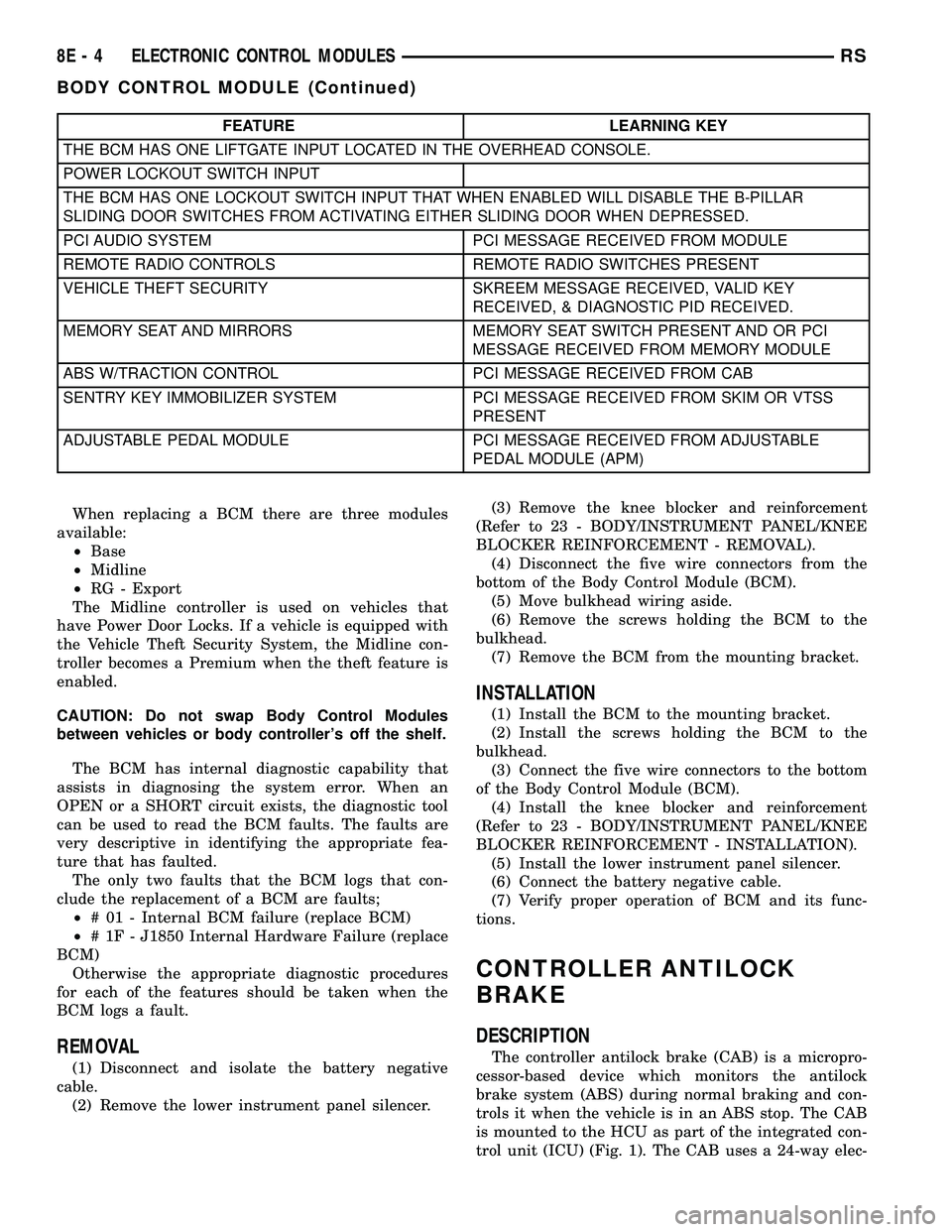
FEATURE LEARNING KEY
THE BCM HAS ONE LIFTGATE INPUT LOCATED IN THE OVERHEAD CONSOLE.
POWER LOCKOUT SWITCH INPUT
THE BCM HAS ONE LOCKOUT SWITCH INPUT THAT WHEN ENABLED WILL DISABLE THE B-PILLAR
SLIDING DOOR SWITCHES FROM ACTIVATING EITHER SLIDING DOOR WHEN DEPRESSED.
PCI AUDIO SYSTEM PCI MESSAGE RECEIVED FROM MODULE
REMOTE RADIO CONTROLS REMOTE RADIO SWITCHES PRESENT
VEHICLE THEFT SECURITY SKREEM MESSAGE RECEIVED, VALID KEY
RECEIVED, & DIAGNOSTIC PID RECEIVED.
MEMORY SEAT AND MIRRORS MEMORY SEAT SWITCH PRESENT AND OR PCI
MESSAGE RECEIVED FROM MEMORY MODULE
ABS W/TRACTION CONTROL PCI MESSAGE RECEIVED FROM CAB
SENTRY KEY IMMOBILIZER SYSTEM PCI MESSAGE RECEIVED FROM SKIM OR VTSS
PRESENT
ADJUSTABLE PEDAL MODULE PCI MESSAGE RECEIVED FROM ADJUSTABLE
PEDAL MODULE (APM)
When replacing a BCM there are three modules
available:
²Base
²Midline
²RG - Export
The Midline controller is used on vehicles that
have Power Door Locks. If a vehicle is equipped with
the Vehicle Theft Security System, the Midline con-
troller becomes a Premium when the theft feature is
enabled.
CAUTION: Do not swap Body Control Modules
between vehicles or body controller's off the shelf.
The BCM has internal diagnostic capability that
assists in diagnosing the system error. When an
OPEN or a SHORT circuit exists, the diagnostic tool
can be used to read the BCM faults. The faults are
very descriptive in identifying the appropriate fea-
ture that has faulted.
The only two faults that the BCM logs that con-
clude the replacement of a BCM are faults;
²# 01 - Internal BCM failure (replace BCM)
²# 1F - J1850 Internal Hardware Failure (replace
BCM)
Otherwise the appropriate diagnostic procedures
for each of the features should be taken when the
BCM logs a fault.
REMOVAL
(1) Disconnect and isolate the battery negative
cable.
(2) Remove the lower instrument panel silencer.(3) Remove the knee blocker and reinforcement
(Refer to 23 - BODY/INSTRUMENT PANEL/KNEE
BLOCKER REINFORCEMENT - REMOVAL).
(4) Disconnect the five wire connectors from the
bottom of the Body Control Module (BCM).
(5) Move bulkhead wiring aside.
(6) Remove the screws holding the BCM to the
bulkhead.
(7) Remove the BCM from the mounting bracket.
INSTALLATION
(1) Install the BCM to the mounting bracket.
(2) Install the screws holding the BCM to the
bulkhead.
(3) Connect the five wire connectors to the bottom
of the Body Control Module (BCM).
(4) Install the knee blocker and reinforcement
(Refer to 23 - BODY/INSTRUMENT PANEL/KNEE
BLOCKER REINFORCEMENT - INSTALLATION).
(5) Install the lower instrument panel silencer.
(6) Connect the battery negative cable.
(7) Verify proper operation of BCM and its func-
tions.
CONTROLLER ANTILOCK
BRAKE
DESCRIPTION
The controller antilock brake (CAB) is a micropro-
cessor-based device which monitors the antilock
brake system (ABS) during normal braking and con-
trols it when the vehicle is in an ABS stop. The CAB
is mounted to the HCU as part of the integrated con-
trol unit (ICU) (Fig. 1). The CAB uses a 24-way elec-
8E - 4 ELECTRONIC CONTROL MODULESRS
BODY CONTROL MODULE (Continued)