Frame CHRYSLER VOYAGER 2005 Workshop Manual
[x] Cancel search | Manufacturer: CHRYSLER, Model Year: 2005, Model line: VOYAGER, Model: CHRYSLER VOYAGER 2005Pages: 2339, PDF Size: 59.69 MB
Page 1230 of 2339

LUBRICATION
DESCRIPTION
The lubrication system is a full-flow filtration,
pressure feed type. The oil pump is mounted in the
front engine cover and driven by the crankshaft.
OPERATION
Engine oil drawn up through the pickup tube and
is pressurized by the oil pump and routed through
the full-flow filter to the main oil gallery running the
length of the cylinder block. A diagonal hole in each
bulkhead feeds oil to each main bearing. Drilled pas-
sages within the crankshaft route oil from main bear-
ing journals to connecting rod journals. Balance shaft
lubrication is provided through an oil passage from
the number one main bearing cap through the bal-
ance shaft carrier support leg. This passage directly
supplies oil to the front bearings and internal
machined passages in the shafts that routes oil from
front to the rear shaft bearing journals. A vertical
hole at the number five bulkhead routes pressurized
oil through a restrictor (integral to the cylinder head
gasket) up past a cylinder head bolt to an oil gallery
running the length of the cylinder head. The cam-shaft journals are partially slotted to allow a prede-
termined amount of pressurized oil to pass into the
bearing cap cavities. Lubrication of the camshaft
lobes are provided by small holes in the camshaft
bearing caps that are directed towards each lobe. Oil
returning to the pan from pressurized components
supplies lubrication to the valve stems. Cylinder
bores and wrist pins are splash lubricated from
directed slots on the connecting rod thrust collars
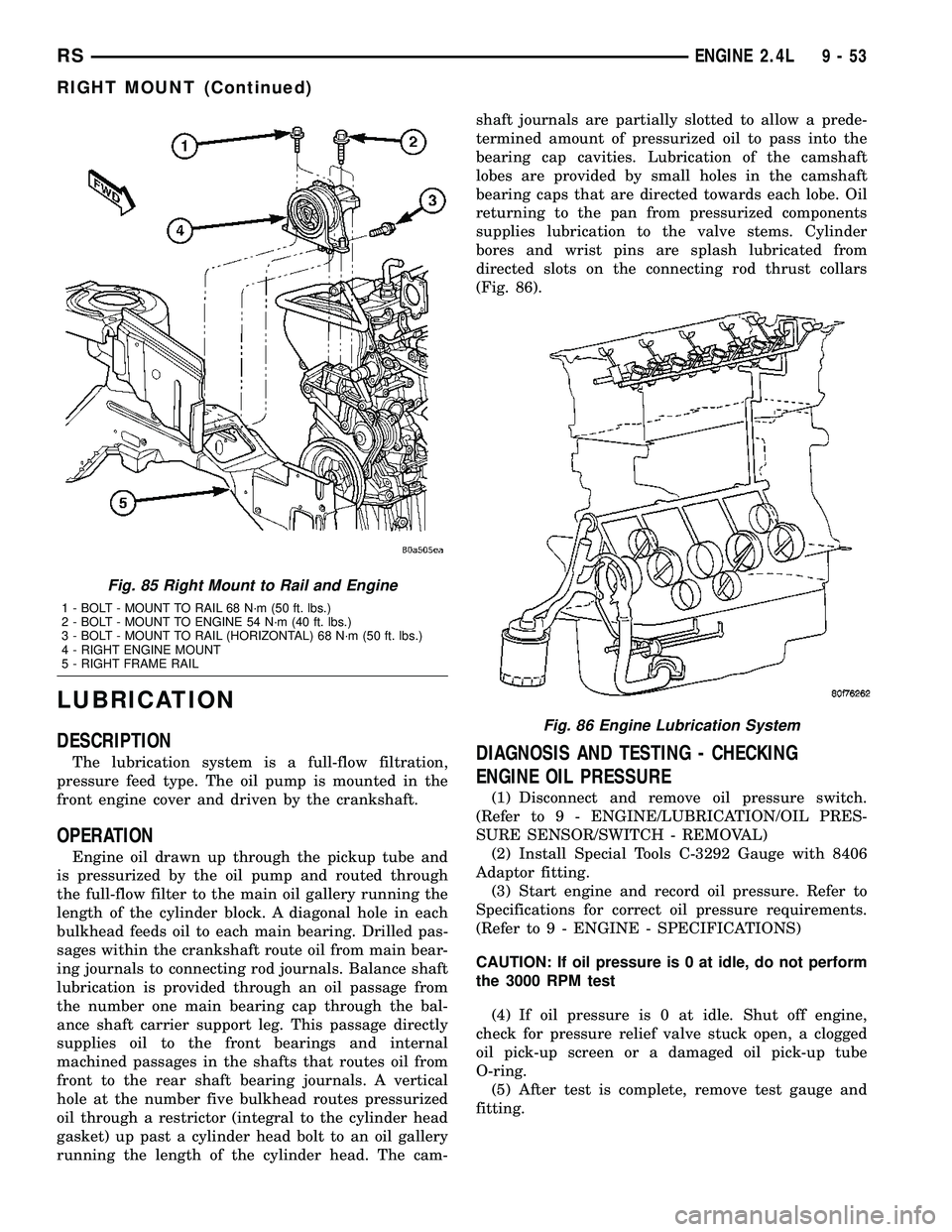
(Fig. 86).
DIAGNOSIS AND TESTING - CHECKING
ENGINE OIL PRESSURE
(1) Disconnect and remove oil pressure switch.
(Refer to 9 - ENGINE/LUBRICATION/OIL PRES-
SURE SENSOR/SWITCH - REMOVAL)
(2) Install Special Tools C-3292 Gauge with 8406
Adaptor fitting.
(3) Start engine and record oil pressure. Refer to
Specifications for correct oil pressure requirements.
(Refer to 9 - ENGINE - SPECIFICATIONS)
CAUTION: If oil pressure is 0 at idle, do not perform
the 3000 RPM test
(4) If oil pressure is 0 at idle. Shut off engine,
check for pressure relief valve stuck open, a clogged
oil pick-up screen or a damaged oil pick-up tube
O-ring.
(5) After test is complete, remove test gauge and
fitting.
Fig. 85 Right Mount to Rail and Engine
1 - BOLT - MOUNT TO RAIL 68 N´m (50 ft. lbs.)
2 - BOLT - MOUNT TO ENGINE 54 N´m (40 ft. lbs.)
3 - BOLT - MOUNT TO RAIL (HORIZONTAL) 68 N´m (50 ft. lbs.)
4 - RIGHT ENGINE MOUNT
5 - RIGHT FRAME RAIL
Fig. 86 Engine Lubrication System
RSENGINE 2.4L9-53
RIGHT MOUNT (Continued)
Page 1267 of 2339

(41) Disconnect the knock sensor electrical connec-
tor (3.8L only).
(42) Disconnect the engine block heater electrical
connector (if equipped).
(43) Remove the accessory belt splash shield.
(44) Remove accessory drive belt (Refer to 7 -
COOLING/ACCESSORY DRIVE/DRIVE BELTS -
REMOVAL).
(45) Disconnect the radiator lower hose.
(46) Remove air conditioning compressor from
engine.
(47) Remove the generator (Refer to 8 - ELECTRI-
CAL/CHARGING/GENERATOR - REMOVAL).
(48) Remove the water pump pulley attaching
bolts and position pulley between pump hub and
housing.
(49) Disconnect the oil pressure switch electrical
connector.
(50) Disconnect wiring harness support clip from
engine oil dipstick tube.
(51) Install Special Tools 6912 and 8444 Adapters
on the right side (rear) of engine block (Fig. 9).
(52) Lower the vehicle.
(53) Remove the power steering pump and set
aside.(54) Raise vehicle enough to allow engine dolly
Special Tool 6135 and cradle Special Tool 6710 with
post Special Tool 6848 and adaptor Special Tool 6909
to be installed under vehicle (Fig. 12).
(55) Loosen cradle/post mounts to allow movement
for positioning posts into locating holes on the engine
(Fig. 10) and (Fig. 11). Slowly lower vehicle and posi-
tion cradle/post mounts until the engine is resting on
posts. Tighten all cradle/post mounts to cradle frame.
This will keep mounts from moving when removing
or installing engine and transmission.
(56) Lower vehicle so the weight ofONLY THE
ENGINE AND TRANSMISSIONis on the cradle.
(57) Install and secure the safety straps to the cra-
dle fixture and around the engine (Fig. 12).
(58) Remove the engine right side mount to engine
attaching bolts (Fig. 13).
(59) Remove the left mount through bolt (Fig. 14).
Fig. 8 POWERTRAIN SUPPORTS AND DUST COVER
1 - BRACKET - ENGINE REAR MOUNT
2 - BOLT - TRANSAXLE CASE COVER
3 - STRUT - TRANSAXLE TO ENGINE HORIZONTAL
4 - BOLT - HORIZONTAL STRUT
5 - BOLT - STRUT TO TRANSAXLE
6 - COVER - TRANSAXLE CASE LOWER
7 - STRUT - TRANSAXLE TO ENGINE
8 - BOLT - STRUT TO ENGINE
9 - BOLT - ENGINE REAR MOUNT BRACKET
Fig. 9 ADAPTER TOOLS MOUNTED ON BLOCK
1 - SPECIAL TOOL 6912
2 - SPECIAL TOOL 8444
Fig. 10 Positioning Special Tool 6848 for use with
Adapters 8444 & 6912
1 - SLOTS
2 - SPECIAL TOOLS 6848
9 - 90 ENGINE 3.3/3.8LRS
ENGINE 3.3/3.8L (Continued)
Page 1269 of 2339

(9) Raise vehicle.
(10) Attach wiring harness support clip to the
engine oil dipstick tube.
(11) Connect oil pressure switch electrical connec-
tor.
(12) Install the A/C compressor.
(13) Install the water pump pulley.
(14) Connect the radiator lower hose.
(15) Install the accessory drive belt and splash
shield (Refer to 7 - COOLING/ACCESSORY DRIVE/
DRIVE BELTS - INSTALLATION).(16) Connect the engine block heater electrical con-
nector (if equipped).
(17) Connect the knock sensor electrical connector
(3.8L only).
(18) Install the torque converter to flex plate bolts.
(19) Install the transaxle case cover (Fig. 8).
(20) Install the powertrain struts (Fig. 8).
(21) Install the engine rear mount bracket.
(22) Install the engine front mount and bracket
assembly.
(23)AWD equipped;Install the power transfer
unit (PTU) (Refer to 21 - TRANSMISSION/TRANS-
AXLE/POWER TRANSFER UNIT - INSTALLA-
TION).
(24) Install the axle shafts (Refer to 3 - DIFFER-
ENTIAL & DRIVELINE/HALF SHAFT - INSTALLA-
TION).
(25) Connect exhaust pipe to manifold (Fig. 7).
(26) Install crossmember cradle plate (Fig. 6).
(27) Lower vehicle.
(28) Connect transaxle shift linkage.
(29) Connect transaxle electrical connectors.
(30) Remove plugs from transmission cooler hoses
and install transaxle oil cooler line service splice kit.
Refer to instructions included with kit.
(31) Install transaxle dipstick tube and attach
electrical harness clip.
(32) Connect the A/C lines to compressor.
(33) Connect the A/C compressor electrical connec-
tor.
(34) Evacuate and recharge A/C system.
(35) Connect crankshaft and camshaft position
sensors.
(36) Connect the fuel injector electrical harness
connector and engage clip to support bracket.
(37) Connect engine coolant temperature (ECT)
sensor and ignition coil electrical connectors.
(38) Connect the ground strap to rear of cylinder
head.
(39) Install power steering reservoir.
(40) Engage wire harness clip to engine right side
mount.
(41) Connect the brake booster and speed control
vacuum hoses.
(42) Connect the vacuum hoses to the throttle
body.
(43) Connect the EGR transducer electrical connec-
tor (if equipped).
(44) Connect the TPS, IAC, and MAP sensor elec-
trical connectors.
(45) Connect throttle cables to throttle body.
(46) Install the radiator fans (Refer to 7 - COOL-
ING/ENGINE/RADIATOR FAN - INSTALLATION).
(47) Connect the radiator upper hose.
(48) Connect the heater hoses. Remove pinch-off
pliers from the rear heater hoses (if equipped).
Fig. 13 Right Mount to Engine
1 - BOLT
2 - MOUNT BRACKET
3 - ENGINE RIGHT MOUNT ASSEMBLY
Fig. 14 LEFT MOUNT TO FRAME BRACKET
1 - FRAME BRACKET
2 - FRAME RAIL - LEFT
3 - BOLT
4 - TRANSAXLE MOUNT
9 - 92 ENGINE 3.3/3.8LRS
ENGINE 3.3/3.8L (Continued)
Page 1311 of 2339

ENGINE MOUNTING
DESCRIPTION
The engine mounting system consist of four
mounts; right and a left side support the powertrain,
and a front and a rear mount control powertrain
torque. The right side mount is a hydro-type (Fig.
87), all others are of molded rubber material.
FRONT MOUNT
REMOVAL
(1) Support the engine and transmission assembly
with a floor jack so it will not rotate.
(2) Remove the front engine mount through bolt
from the insulator and front crossmember mounting
bracket (Fig. 88).
(3) Remove six screws from air dam to allow
access to the front mount screws.
(4) Remove the front engine mount screws and
remove the insulator assembly (Fig. 88).
(5) Remove the front mounting bracket, if neces-
sary (Fig. 88).
INSTALLATION
(1) Install the front mounting bracket, if removed
(Fig. 88).
(2) Install the front engine mount through bolt
from the insulator and front crossmember mounting
bracket (Fig. 88).
(3) Install the insulator assembly and mounting
screws (Fig. 88).
Fig. 87 Engine Hydro-type Mount - Right Side
1 - BOLT
2 - BOLT
3 - FRAME RAIL
4 - RIGHT MOUNT - 2.4L ENGINE
5 - RIGHT MOUNT - 3.3/3.8L ENGINE
9 - 134 ENGINE 3.3/3.8LRS
Page 1313 of 2339

LEFT MOUNT
REMOVAL
(1) Raise the vehicle on hoist.
(2) Remove the left front wheel.
(3) Remove the left mount through bolt access
cover.
(4) Support the transaxle with a suitable jack.
(5) Remove the engine front mount through bolt to
allow left mount removal clearance (Fig. 88).
(6) Remove the left mount through frame rail bolt
(Fig. 89).
(7) Lower transaxle for access to horizontal bolts.
(8) Remove the horizontal bolts from the mount to
the transaxle (Fig. 90).
NOTE: To remove mount, additional lowering of
transaxle may be required.
(9) Remove left mount.
INSTALLATION
(1) Install left mount on transaxle (Fig. 90).
(2) Raise transaxle with jack until left mount is in
position.
(3) Install left mount through bolt (Fig. 89).
(4) Install left mount through bolt access cover.
(5) Install front mount through bolt (Fig. 88).
(6) Install left front wheel.
(7) Lower vehicle.
REAR MOUNT
REMOVAL
(1) Raise vehicle on hoist.
(2) Remove the rear mount heat shield (Fig. 91).
(3) Remove the through bolt from the mount and
rear mount bracket (Fig. 92).
(4) Remove the mount bolts (Fig. 92).
(5) Remove the rear mount (Fig. 92).
(6) For rear mount bracket removal, remove the
bolts attaching bracket to transaxle (Fig. 93).
(7) Remove rear mount bracket.
Fig. 89 LEFT MOUNT TO BRACKET
1 - BOLT - BRACKET TO FRAME RAIL 68 N´m (50 ft. lbs.)
2 - BOLT - MOUNT TO RAIL THRU 75 N´m (55 ft. lbs.)
3 - BOLT - LEFT MOUNT TO TRANSAXLE 54 N´m (40 ft. lbs.)
4 - TRANSAXLE
5 - MOUNT - LEFT
6 - BRACKET - LEFT MOUNT
Fig. 90 LEFT MOUNT - 41TE TRANSAXLE
1 - LEFT MOUNT ASSEMBLY
2 - BOLT - 54 N´m (40 ft. lbs.)
3 - TRANSAXLE - 41TE
Fig. 91 Rear Mount Heat Shield
1 - BOLT - HEAT SHIELD 11 N´m (100 in. lbs.)
2 - HEAT SHIELD
3 - CLIP
4 - REAR MOUNT
9 - 136 ENGINE 3.3/3.8LRS
Page 1315 of 2339

RIGHT MOUNT
REMOVAL
(1) Remove air cleaner housing lid and clean air
hose from throttle body.
(2) Remove air cleaner element and housing.
(3) Disconnect make-up air hose from cylinder
head cover.
(4) Remove the load on the right engine mount by
carefully supporting the engine assembly with a floor
jack.
(5) Disconnect electrical harness support clips from
engine mount bracket.
(6) Remove the bolts attaching the engine mount
to the frame rail (Fig. 94).
(7) Remove the three bolts attaching the engine
mount to the engine bracket (Fig. 94).
(8) Remove the right engine mount (Fig. 94).
INSTALLATION
(1) Install engine bracket (if removed). Tighten
bolts to 33 N´m (24 ft. lbs.).
(2) Position right engine mount and install frame
rail to mount bolts (Fig. 94). Tighten bolts to 68 N´m
(50 ft. lbs.).
(3) Install the mount to engine bracket bolts and
tighten to 54 N´m (40 ft. lbs.). (Fig. 94)
(4) Connect electrical harness support clips to
engine mount bracket.
(5) Remove jack from under engine.
(6) Connect make-up air hose to cylinder head
cover.
(7) Install air cleaner housing and element.
(8) Install air cleaner housing lid and clean air
tube to throttle body.
LUBRICATION
DESCRIPTION
The lubrication system is a full flow filtration pres-
sure feed type. The oil pump is mounted in the tim-
ing chain cover and is driven by the crankshaft
OPERATION
Oil from the oil pan is pumped by a internal gear
type oil pump directly coupled to the crankshaft. The
pressure is regulated by a relief valve located in the
timing chain cover. The oil is pumped through an oil
filter and feeds a main oil gallery. This oil gallery
feeds oil under pressure to the main and rod bear-
ings, camshaft bearings. Passages in the cylinder
block feed oil to the hydraulic lifters and rocker shaft
brackets which feeds the rocker arm pivots (Fig. 95).
DIAGNOSIS AND TESTING - ENGINE OIL
PRESSURE
(1) Disconnect and remove oil pressure switch
(Refer to 9 - ENGINE/LUBRICATION/OIL PRES-
SURE SENSOR/SWITCH - REMOVAL).
(2) Install Special Tools C-3292 Gauge with 8406
Adaptor. For Special Tool identification, (Refer to 9 -
ENGINE - SPECIAL TOOLS).
(3) Start engine and record oil pressure. Refer to
Oil Pressure in Engine Specifications for the correct
pressure (Refer to 9 - ENGINE - SPECIFICATIONS).
Fig. 94 Right Engine Mount
1 - RIGHT ENGINE MOUNT
2 - BOLT - MOUNT TO FRAME RAIL
3 - BOLT - MOUNT TO ENGINE
4 - ENGINE MOUNT BRACKET
5 - RIGHT FRAME RAIL
9 - 138 ENGINE 3.3/3.8LRS
Page 1348 of 2339

FRAME & BUMPERS
TABLE OF CONTENTS
page page
BUMPERS
SPECIFICATIONS - TORQUE...............1
FRONT FASCIA
REMOVAL.............................1
INSTALLATION..........................1
FRONT BUMPER REINFORCEMENT
REMOVAL.............................3
INSTALLATION..........................3
REAR FASCIA
REMOVAL.............................4
INSTALLATION..........................4
REAR BUMPER REINFORCEMENT
REMOVAL.............................5
INSTALLATION..........................5
REAR FASCIA - SCUFF PAD
REMOVAL.............................5
INSTALLATION..........................5FRAME
SPECIFICATIONS
SPECIFICATIONS - FRAME DIMENSIONS . . . 6
SPECIFICATIONS - FRAME DIMENSIONS -
FOLD-IN-FLOOR SEATS ONLY...........11
SPECIFICATIONS - TORQUE............14
FRONT CRADLE CROSSMEMBER
DESCRIPTION
DESCRIPTION - FRONT CRADLE
CROSSMEMBER......................14
DESCRIPTION - FRONT CRADLE
CROSSMEMBER THREAD REPAIR........14
REMOVAL.............................15
INSTALLATION.........................16
FRONT CROSSMEMBER MOUNT BUSHINGS
REMOVAL.............................17
INSTALLATION.........................17
BUMPERS
SPECIFICATIONS - TORQUE
DESCRIPTION N´m Ft. Lbs. In. Lbs.
Front bumper reinforcement attaching nut 54 40 Ð
Rear bumper reinforcement attaching nut 27 20 Ð
FRONT FASCIA
REMOVAL
(1) Release hood latch and open hood.
(2) Remove the headlamp assemblies (Refer to 8 -
ELECTRICAL/LAMPS/LIGHTING - EXTERIOR/
HEADLAMP - REMOVAL).
(3) Hoist vehicle and support with safety stands.
(4) Remove the five push pin fasteners attaching
bottom of fascia/air dam to radiator closure panel.
(5) Remove front wheels.
(6) Remove front wheelhouse splash shields fasten-
ers as necessary to gain access to bolts attaching
front fascia to fender. (Refer to 23 - BODY/EXTERI-
OR/ WHEELHOUSE SPLASH SHIELD -
REMOVAL).(7) Remove the two bolts and two nuts attaching
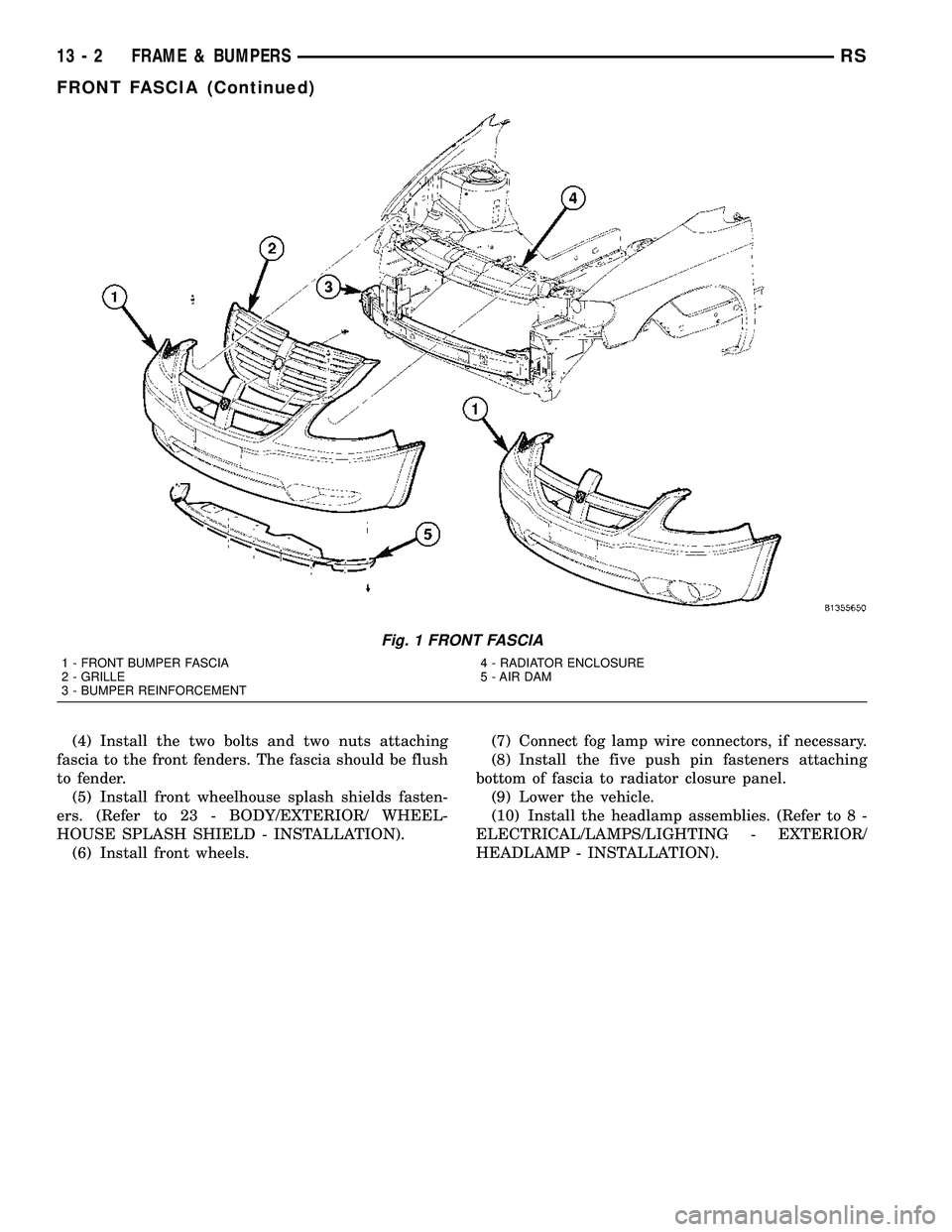
fascia to the front fenders (Fig. 1) and (Fig. 2).
(8) Disconnect fog lamp wire connectors, if neces-
sary.
(9) Lower vehicle.
(10) Remove two bolts attaching the upper grille
support to the headlamp mounting panel at each side
of the grille.
(11) Remove bumper fascia from vehicle.
INSTALLATION
(1) Position front bumper fascia on vehicle (Fig. 1)
and (Fig. 2).
(2) Install the two bolts attaching fascia to head-
lamp mounting panel at each side of grille.
(3) Hoist vehicle and support with safety stands.
RSFRAME & BUMPERS13-1
Page 1349 of 2339

(4) Install the two bolts and two nuts attaching
fascia to the front fenders. The fascia should be flush
to fender.
(5) Install front wheelhouse splash shields fasten-
ers. (Refer to 23 - BODY/EXTERIOR/ WHEEL-
HOUSE SPLASH SHIELD - INSTALLATION).
(6) Install front wheels.(7) Connect fog lamp wire connectors, if necessary.
(8) Install the five push pin fasteners attaching
bottom of fascia to radiator closure panel.
(9) Lower the vehicle.
(10) Install the headlamp assemblies. (Refer to 8 -
ELECTRICAL/LAMPS/LIGHTING - EXTERIOR/
HEADLAMP - INSTALLATION).
Fig. 1 FRONT FASCIA
1 - FRONT BUMPER FASCIA
2 - GRILLE
3 - BUMPER REINFORCEMENT4 - RADIATOR ENCLOSURE
5 - AIR DAM
13 - 2 FRAME & BUMPERSRS
FRONT FASCIA (Continued)
Page 1350 of 2339

FRONT BUMPER
REINFORCEMENT
REMOVAL
(1) Remove front bumper fascia. (Refer to 13 -
FRAMES & BUMPERS/BUMPERS/FRONT FASCIA
- REMOVAL)
(2) Disconnect the solid state relay (SSR) for the
cooling module wiring connector. If bumper reinforce-
ment is being replaced, remove the solid state relay.
(3) Support front bumper reinforcement on a suit-
able lifting device.
(4) Remove the four nuts attaching front bumper
reinforcement to frame rail (Fig. 3).
(5) Remove front bumper reinforcement from vehi-
cle.
INSTALLATION
NOTE: Check position of the arrows molded into
the foam for correct orientation.
Fig. 2 FRONT FASCIA
1 - GRILLE
2 - FRONT BUMPER FIASCO
3 - BUMPER REINFORCEMENT4 - RADIATOR ENCLOSURE
5 - AIR DAM
Fig. 3 FRONT BUMPER REINFORCEMENT
1 - FRONT BUMPER REINFORCEMENT
2 - FRAME RAILS
RSFRAME & BUMPERS13-3
FRONT FASCIA (Continued)
Page 1351 of 2339

(1) Support front bumper reinforcement using a
suitable lifting device and lift into position.
(2) Install the four nuts attaching reinforcement to
frame rails. Tighten nuts to 54 N´m (40 ft. lbs.)
torque.
(3) Connect the solid state relay (SSR) wiring con-
nector. If bumper reinforcement was replaced, install
the solid state relay onto the bumper reinforcement.
(4) Install front fascia. (Refer to 13 - FRAMES &
BUMPERS/BUMPERS/FRONT FASCIA - INSTAL-
LATION).
REAR FASCIA
REMOVAL
(1) Open liftgate.
(2) Remove attaching screw from upper fascia to
the liftgate tower, right side and left side.
(3) Hoist and support vehicle with safety stands.
(4) Disconnect rear park assist wire connector, if
equipped.
(5) Remove the three screws attaching rear fascia
to rear fascia brackets on right side and left side
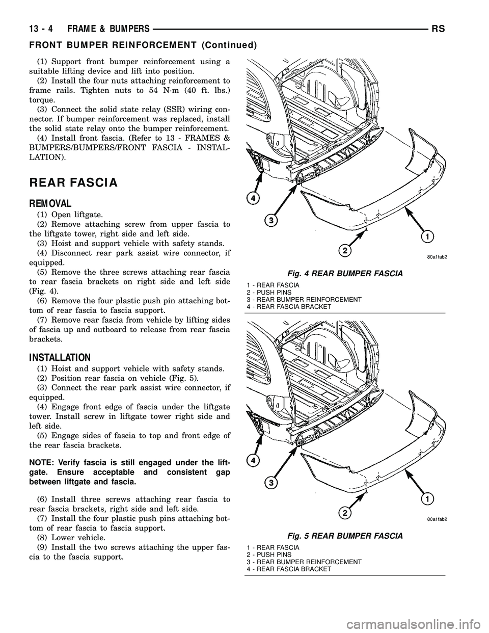
(Fig. 4).
(6) Remove the four plastic push pin attaching bot-
tom of rear fascia to fascia support.
(7) Remove rear fascia from vehicle by lifting sides
of fascia up and outboard to release from rear fascia
brackets.
INSTALLATION
(1) Hoist and support vehicle with safety stands.
(2) Position rear fascia on vehicle (Fig. 5).
(3) Connect the rear park assist wire connector, if
equipped.
(4) Engage front edge of fascia under the liftgate
tower. Install screw in liftgate tower right side and
left side.
(5) Engage sides of fascia to top and front edge of
the rear fascia brackets.
NOTE: Verify fascia is still engaged under the lift-
gate. Ensure acceptable and consistent gap
between liftgate and fascia.
(6) Install three screws attaching rear fascia to
rear fascia brackets, right side and left side.
(7) Install the four plastic push pins attaching bot-
tom of rear fascia to fascia support.
(8) Lower vehicle.
(9) Install the two screws attaching the upper fas-
cia to the fascia support.
Fig. 4 REAR BUMPER FASCIA
1 - REAR FASCIA
2 - PUSH PINS
3 - REAR BUMPER REINFORCEMENT
4 - REAR FASCIA BRACKET
Fig. 5 REAR BUMPER FASCIA
1 - REAR FASCIA
2 - PUSH PINS
3 - REAR BUMPER REINFORCEMENT
4 - REAR FASCIA BRACKET
13 - 4 FRAME & BUMPERSRS
FRONT BUMPER REINFORCEMENT (Continued)