Frame CHRYSLER VOYAGER 2005 Owner's Guide
[x] Cancel search | Manufacturer: CHRYSLER, Model Year: 2005, Model line: VOYAGER, Model: CHRYSLER VOYAGER 2005Pages: 2339, PDF Size: 59.69 MB
Page 527 of 2339

accessible from the rear after the D-pillar trim is
removed.
(10) Remove quarter trim bolster.
(11) Remove quarter trim panel screws.
(12) Remove quarter trim panel.
(13) Remove first row seat belt and retractor
retaining bolt.
(14) Remove first row seat belt and retractor from
vehicle.
INSTALLATION
(1) Install first row seat belt and retractor. Torque
bolt to 39 N´m (29 ft. lbs.).
(2) Install quarter trim panel.
(3) Install quarter trim panel screws.
(4) Install quarter trim bolster.
(5) Connect speaker connector. The left side has
the speaker mounted in the D-pillar trim cover and
the right side will have the speaker mounted in the
rear of the quarter trim panel, but the connector is
accessible from the rear after the D-pillar trim is
removed.
(6) Install D-pillar trim cover.
(7) Install second seat belt lower anchor bolt.
Torque bolt to 39 N´m (29 ft. lbs.).
(8) Install second seat belt upper turning loop
anchor bolt. Torque bolt to 39 N´m (29 ft. lbs.).
(9) Install upper liftgate trim.
(10) Install liftgate sill plate.
(11) Install first row seat belt upper turning loop
anchor bolt. Torque bolt to 39 N´m (29 ft. lbs.).
(12) Install first row seat belt lower anchor bolt.
Torque bolt to 39 N´m (29 ft. lbs.).
(13) Install first and second row seats.
SEAT BELT BUCKLE - SECOND
ROW - THREE PASSENGER
BENCH
REMOVAL
(1) Remove bolt attaching seat belt buckle to seat
rear frame rail (Fig. 50).
(2) Remove seat belt buckle from seat.
INSTALLATION
(1) Place seat belt buckle in position on seat.
(2) Install bolt to attach seat belt buckle to seat
rear frame rail. Tighten all seat belt bolts to 39 N´m
(29 ft. lbs.) torque.
SEAT BELT & RETRACTOR -
SECOND ROW - RIGHT
OUTBOARD
REMOVAL
(1) Remove first and second row seats.
(2) Remove first row seat belt lower anchor bolt.
(3) Remove first row seat belt upper anchor bolt.
(4) Remove liftgate sill plate.
(5) Remove upper liftgate trim.
(6) Remove second seat belt lower anchor bolt.
(7) Remove second seat belt upper anchor bolt.
(8) Remove D-pillar trim cover.
(9) Disconnect speaker connector. The left side has
the speaker mounted in the D-pillar trim cover and
the right side will have the speaker mounted in the
rear of the quarter trim panel, but the connector is
accessible from the rear after the D-pillar trim is
removed.
(10) Remove quarter trim bolster.
(11) Remove quarter trim panel screws.
(12) Remove quarter trim panel.
(13) Remove retractor retaining bolt.
(14) Remove second row seat belt and retractor.
INSTALLATION
(1) Install second row seat belt and retractor.
Torque bolt to 39 N´m (29 ft. lbs.).
(2) Install quarter trim panel.
(3) Install quarter trim panel screws.
(4) Install quarter trim bolster.
(5) Connect speaker connector. The left side has
the speaker mounted in the D-pillar trim cover and
Fig. 50 SEAT BELT BUCKLE - SECOND ROW -
THREE PASSENGER BENCH
1 - ANCHOR BOLT
2 - SEAT BELTS
3 - ANCHOR
4 - RISER
8O - 40 RESTRAINTSRS
SEAT BELT & RETRACTOR - FIRST ROW - OUTBOARD (Continued)
Page 530 of 2339
SEAT BELT TENSIONER
DESCRIPTION
The seat belt system incorporates Seat Belt Ten-
sioners. The tensioner is designed to hold the occu-
pant in their respective seat by retracting the seat
belt up to four inches. They are integral to the front
seat belt buckles and cannot be serviced. If found
defective they must be replaced. After an airbag
deployment, the tensioner must be replaced.
Seat Belt Tensioners supplement the dual front air-
bag system. The seat belt tensioners are integral to
the front seat belt buckles, which are secured to the
seat cushion frame on the inboard side. The seat belt
tensioners are controlled by the Occupant Restraint
Controller (ORC) and are connected to the vehicle
electrical system through the body wire harness.
The seat belt tensioners cannot be repaired and, if
faulty or damaged, the entire front seat belt buckle
must be replaced. The seat belt tensioners are not
intended for reuse and must be replaced following
any front airbag deployment.
OPERATION
WARNING: When the front airbag is deployed, the
tensioner will have deployed also and should be
replaced. Failure to do so could result in occupant
personal injury or death.
The seat belt tensioners are deployed by a signal
generated by the Occupant Restraint Controller
(ORC) through the driver or passenger seat belt ten-
sioner line 1 and line 2 (or squib) circuits. When the
ORC sends the proper electrical signal to the tension-
ers, the electrical energy generates enough heat to
initiate a small pyrotechnic gas generator.
Removing excess slack from the front seat belts not
only keeps the occupants properly positioned for an
airbag deployment following a frontal impact of the
vehicle, but also helps to reduce injuries that the
occupants of the front seat might experience in these
situations as a result of a harmful contact with the
steering wheel, steering column, instrument panel
and/or windshield.
The ORC monitors the condition of the seat belt
tensioners through circuit resistance, and will illumi-
nate the airbag indicator in the ElectroMechanical
Instrument Cluster (EMIC) and store a Diagnostic
Trouble Code (DTC) for any fault that is detected.
For proper diagnosis of the seat belt tensioners, use a
scan tool and the appropriate diagnostic information.
SEAT WEIGHT BLADDER &
PRESSURE SENSOR
DESCRIPTION
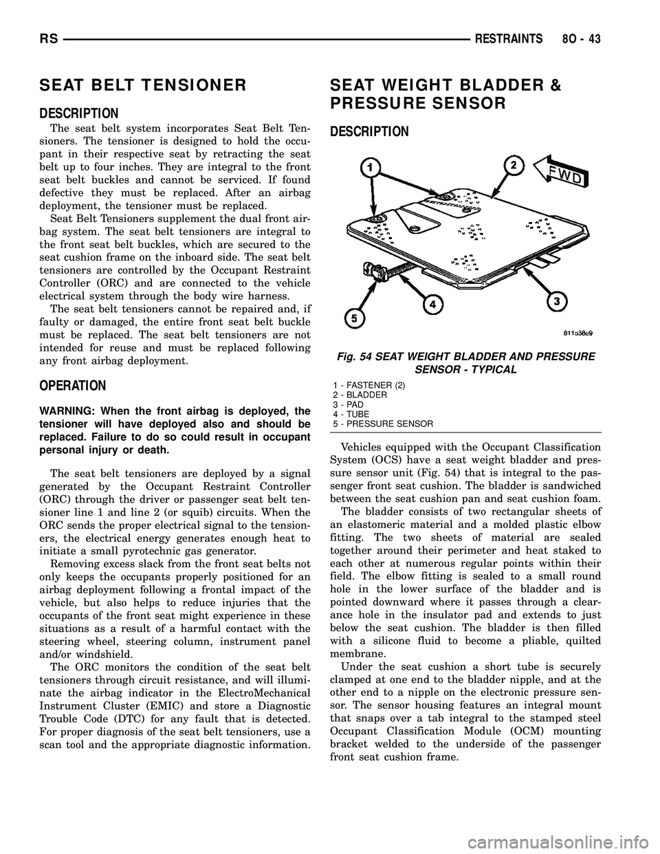
Vehicles equipped with the Occupant Classification
System (OCS) have a seat weight bladder and pres-
sure sensor unit (Fig. 54) that is integral to the pas-
senger front seat cushion. The bladder is sandwiched
between the seat cushion pan and seat cushion foam.
The bladder consists of two rectangular sheets of
an elastomeric material and a molded plastic elbow
fitting. The two sheets of material are sealed
together around their perimeter and heat staked to
each other at numerous regular points within their
field. The elbow fitting is sealed to a small round
hole in the lower surface of the bladder and is
pointed downward where it passes through a clear-
ance hole in the insulator pad and extends to just
below the seat cushion. The bladder is then filled
with a silicone fluid to become a pliable, quilted
membrane.
Under the seat cushion a short tube is securely
clamped at one end to the bladder nipple, and at the
other end to a nipple on the electronic pressure sen-
sor. The sensor housing features an integral mount
that snaps over a tab integral to the stamped steel
Occupant Classification Module (OCM) mounting
bracket welded to the underside of the passenger
front seat cushion frame.
Fig. 54 SEAT WEIGHT BLADDER AND PRESSURE
SENSOR - TYPICAL
1 - FASTENER (2)
2 - BLADDER
3-PAD
4 - TUBE
5 - PRESSURE SENSOR
RSRESTRAINTS8O-43
Page 531 of 2339

The seat weight bladder and pressure sensor can-
not be adjusted or repaired. The components of the
passenger front seat cushion of a vehicle equipped
with the OCS including the cushion frame, seat
weight bladder and pressure sensor, seat cushion
foam, wire harness and the OCM are serviced only as
a factory-calibrated, assembled and tamper-evident
unit. Only the OCM and the seat cushion trim are
available for separate service replacement. Once a
service replacement package has been installed in a
vehicle, the OCM can thereafter be serviced only by
replacing the entire passenger front seat cushion unit
with another complete service replacement package.
OPERATION
The seat weight bladder and pressure sensor unit
is designed to sense the relative weight of a load
applied to the passenger front seat cushion, which
provides a logic input to the microprocessor of theOccupant Classification Module (OCM). When a load
is applied to the seat cushion, fluid within the blad-
der becomes pressurized. These changes in bladder
fluid pressure are measured by the pressure sensor
under the seat cushion through the bladder tube. As
the pressure within the bladder changes, the cir-
cuitry of the pressure sensor changes the output volt-
age of the sensor.
The pressure sensor receives a nominal five volts
and a ground through hard wired circuits from the
OCM. The OCM then monitors the pressure sensor
output voltage on the Programmable Communication
Interface (PCI) data bus circuit.
To properly diagnose the seat weight bladder and
pressure sensor, its communication with/between the
OCM, and all other components within the OCS, use
a scan tool and the appropriate diagnostic
information.
8O - 44 RESTRAINTSRS
SEAT WEIGHT BLADDER & PRESSURE SENSOR (Continued)
Page 1119 of 2339

CONNECTOR NAME/NUMBER COLOR LOCATION FIG.
Hands Free Module C2 BK Instrument Panel N/S
Hands Free Module C3 Instrument Panel N/S
Headlamp Switch BK Rear of Switch 20, 21, 30
Headlamp Washer Pump Motor
(Export)BK At Motor 3
High Note Horn BK Left Frame Rail 5
Hood Ajar Switch (Export) BK Left Fender 6
Idle Air Control Motor (Gas) BK On Throttle Body 10, 11 17
Ignition Coil (2.4L) BK Top of Valve Cover 10, 11
Ignition Coil (3.3L/ 3.8L) DKGY Top of Engine 17, 18
Ignition Switch BK Rear of Switch at Steering Column 20, 21, 22, 23, 31
Inlet Air Temperature Sensor BK Top Left of Engine 9, 10, 11, 17
Input Speed Sensor GY Front of Transmission 14, 19
Instrument Cluster BK Rear of Cluster 20, 21, 28
Instrument Panel Switch Bank
(Heated Seats)BK Right Center of Instrument Panel 20, 23, 25
Instrument Panel Switch Bank
(Except Heated Seats)Right Center of Instrument Panel 20, 23, 25
Integrated Power Module C1 Left Fender Shield 7
Integrated Power Module C2 GN/BL Left Fender Shield 7
Integrated Power Module C3 Left Fender Shield 7, 11
Integrated Power Module C4 BL Left Fender Shield 7, 11
Integrated Power Module C5 BK Left Fender Shield 7
Integrated Power Module C6 NAT Left Fender Shield 7
Integrated Power Module C7 Left Fender Shield 7
Integrated Power Module C8 OR Left Fender Shield 7
Integrated Power Module C9 BK Left Fender Shield 7
Knock Sensor (Except Export) BK At Engine Block 11
Left B Pillar Switch (Power
Sliding Door)GY Left B Pillar 40
Left Cinch/Release Motor (Power
Sliding Door)GY Left Sliding Door N/S
Left Curtain Airbag Squib Rear of Left Roof Rail 47
Left Cylinder Lock Switch BK At Switch 43
Left Door Speaker BK At Speaker 43
Left Fog Lamp BK At Lamp 5
Left Front Door Ajar Switch
(Base)BK At Switch N/S
Left Front Door Lock Motor/Ajar
Switch (Except Base)BK Left Door 43
Left Front Impact Sensor BK Near T/O for C101 5
Left Front Park/Turn Signal Lamp
(Except Export)DKGY At Lamp 1
Left Front Wheel Speed Sensor GY Left Fender Side Shield 5, 11
8W - 91 - 6 8W-91 CONNECTOR/GROUND/SPLICE LOCATIONRS
CONNECTOR/GROUND/SPLICE LOCATION (Continued)
Page 1122 of 2339

CONNECTOR NAME/NUMBER COLOR LOCATION FIG.
Passenger Door Courtesy Lamp GY At Lamp 44
Passenger Door Lock Switch BK At Switch 44
Passenger Folding Mirror Relay
(Export)BL Left Kick Panel 7
Passenger Heated Seat Back GN At Seat N/S
Passenger Heated Seat Cushion BK At Seat N/S
Passenger Heated Seat Module GY At Heated Seat N/S
Passenger Power Seat Front
Riser MotorRD Under Seat N/S
Passenger Power Seat Horizontal
MotorBK Under Seat N/S
Passenger Power Seat Rear
Riser MotorRD Under Seat N/S
Passenger Power Seat Recliner
MotorGN Under Seat N/S
Passenger Power Seat Switch GN At Switch N/S
Passenger Power Window Motor RD At Motor 44
Passenger Power Window Switch BK At Switch 44
Passenger Seat Belt Switch
(Occupant Sensing)YL On Seat Harness N/S
Passenger Seat Belt Tensioner On Seat Harness N/S
Passenger Seat Weight Sensor BK Passenger Seat N/S
Power Folding Mirror Switch
(Export)BK Near Steering Column 31
Power Liftgate Module C1 BK Left Quarter 46, 47
Power Liftgate Module C2 Left Quarter 46, 47
Power Liftgate Motor BK Left Quarter 47
Power Mirror Switch BK Rear of Switch 30
Power Outlet (Except Lowline) BK Instrument Panel 20, 23, 25
Power Seat Circuit Breaker GY Under Seat N/S
Powertrain Control Module C1 BK Left Front Engine Compartment 11
Powertrain Control Module C2 OR Left Front Engine Compartment 11
Powertrain Control Module C3 NAT Left Front Engine Compartment 11
Powertrain Control Module C4 GN Left Front Engine Compartment 11
Power Window Circuit Breaker GY Left Side Kick Panel 41 42
Radiator Fan No.1 (Gas) BK Left Side At Motor 1
Radiator Fan No.1 (Diesel) GY Left Side At Motor 1
Radiator Fan No.2 (Gas) BK Right Side At Motor 1, 2
Radiator Fan No.2 (Diesel) GY Right Side At Motor 1, 2
Radiator Fan Relay (Gas) Top of Left Front Frame Rail 1
Radiator Fan Relay No. 1
(Diesel)BL Left Front Engine Compartment 2
Radiator Fan Relay No. 2
(Diesel)BL Left Front Engine Compartment 2
RS8W-91 CONNECTOR/GROUND/SPLICE LOCATION8W-91-9
CONNECTOR/GROUND/SPLICE LOCATION (Continued)
Page 1191 of 2339
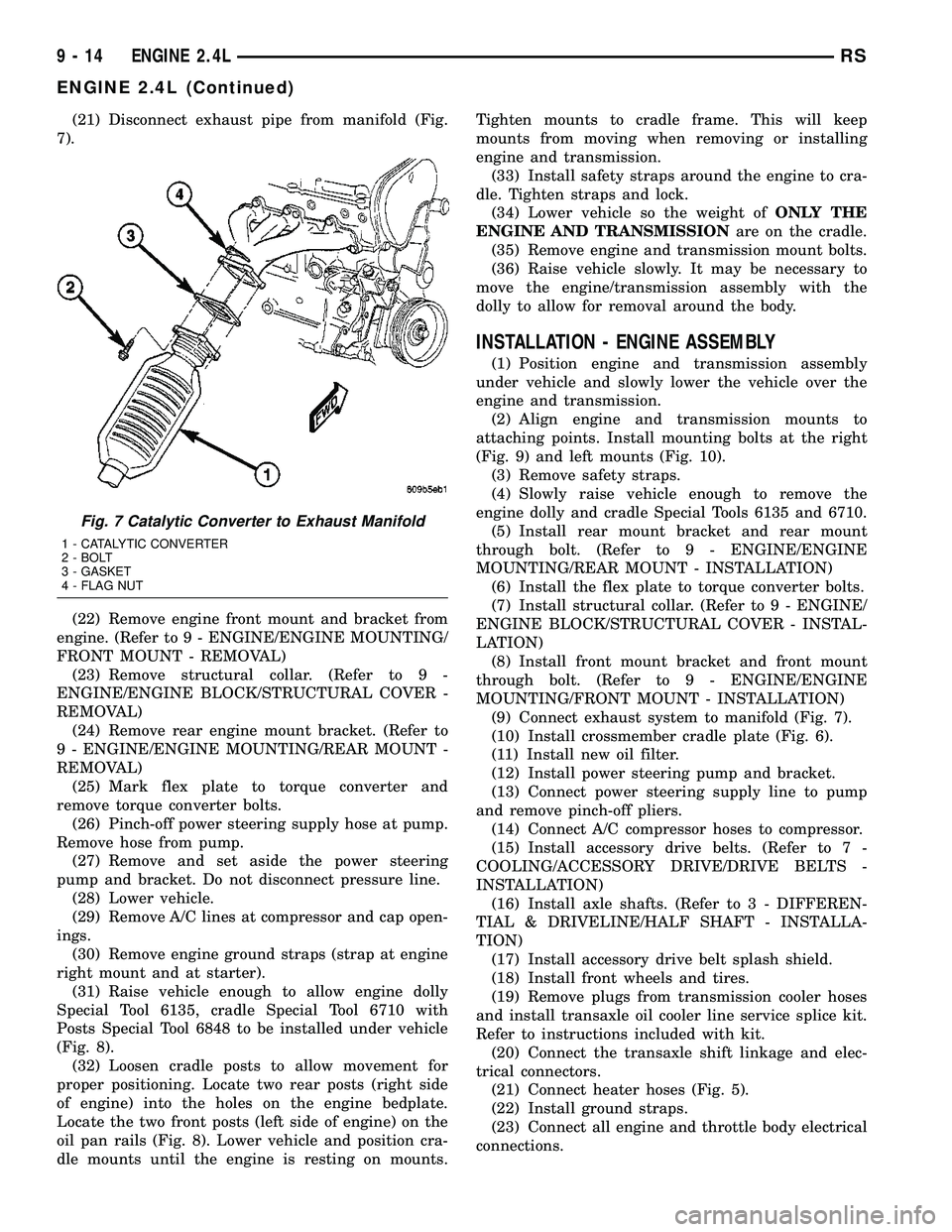
(21) Disconnect exhaust pipe from manifold (Fig.
7).
(22) Remove engine front mount and bracket from
engine. (Refer to 9 - ENGINE/ENGINE MOUNTING/
FRONT MOUNT - REMOVAL)
(23) Remove structural collar. (Refer to 9 -
ENGINE/ENGINE BLOCK/STRUCTURAL COVER -
REMOVAL)
(24) Remove rear engine mount bracket. (Refer to
9 - ENGINE/ENGINE MOUNTING/REAR MOUNT -
REMOVAL)
(25) Mark flex plate to torque converter and
remove torque converter bolts.
(26) Pinch-off power steering supply hose at pump.
Remove hose from pump.
(27) Remove and set aside the power steering
pump and bracket. Do not disconnect pressure line.
(28) Lower vehicle.
(29) Remove A/C lines at compressor and cap open-
ings.
(30) Remove engine ground straps (strap at engine
right mount and at starter).
(31) Raise vehicle enough to allow engine dolly
Special Tool 6135, cradle Special Tool 6710 with
Posts Special Tool 6848 to be installed under vehicle
(Fig. 8).
(32) Loosen cradle posts to allow movement for
proper positioning. Locate two rear posts (right side
of engine) into the holes on the engine bedplate.
Locate the two front posts (left side of engine) on the
oil pan rails (Fig. 8). Lower vehicle and position cra-
dle mounts until the engine is resting on mounts.Tighten mounts to cradle frame. This will keep
mounts from moving when removing or installing
engine and transmission.
(33) Install safety straps around the engine to cra-
dle. Tighten straps and lock.
(34) Lower vehicle so the weight ofONLY THE
ENGINE AND TRANSMISSIONare on the cradle.
(35) Remove engine and transmission mount bolts.
(36) Raise vehicle slowly. It may be necessary to
move the engine/transmission assembly with the
dolly to allow for removal around the body.
INSTALLATION - ENGINE ASSEMBLY
(1) Position engine and transmission assembly
under vehicle and slowly lower the vehicle over the
engine and transmission.
(2) Align engine and transmission mounts to
attaching points. Install mounting bolts at the right
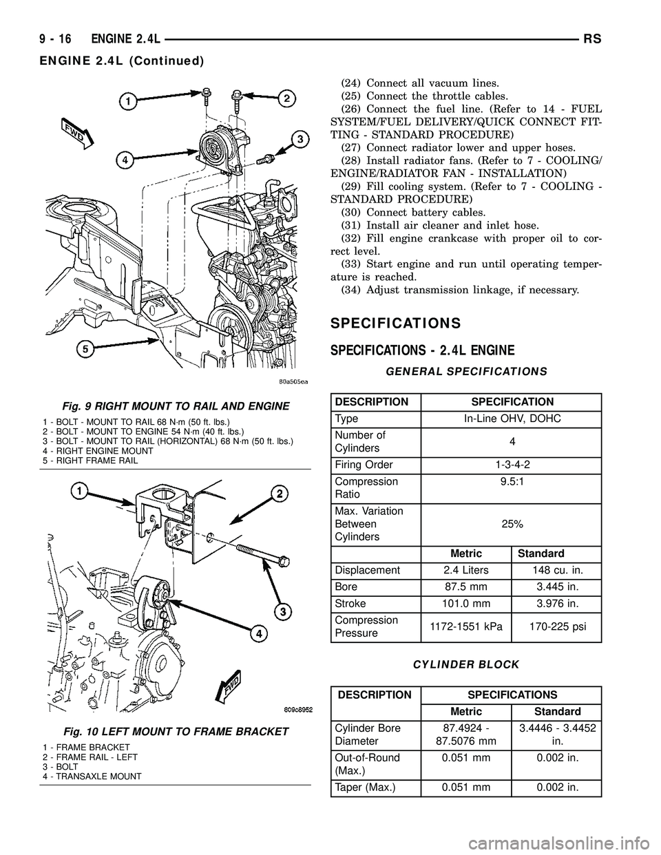
(Fig. 9) and left mounts (Fig. 10).
(3) Remove safety straps.
(4) Slowly raise vehicle enough to remove the
engine dolly and cradle Special Tools 6135 and 6710.
(5) Install rear mount bracket and rear mount
through bolt. (Refer to 9 - ENGINE/ENGINE
MOUNTING/REAR MOUNT - INSTALLATION)
(6) Install the flex plate to torque converter bolts.
(7) Install structural collar. (Refer to 9 - ENGINE/
ENGINE BLOCK/STRUCTURAL COVER - INSTAL-
LATION)
(8) Install front mount bracket and front mount
through bolt. (Refer to 9 - ENGINE/ENGINE
MOUNTING/FRONT MOUNT - INSTALLATION)
(9) Connect exhaust system to manifold (Fig. 7).
(10) Install crossmember cradle plate (Fig. 6).
(11) Install new oil filter.
(12) Install power steering pump and bracket.
(13) Connect power steering supply line to pump
and remove pinch-off pliers.
(14) Connect A/C compressor hoses to compressor.
(15) Install accessory drive belts. (Refer to 7 -
COOLING/ACCESSORY DRIVE/DRIVE BELTS -
INSTALLATION)
(16) Install axle shafts. (Refer to 3 - DIFFEREN-
TIAL & DRIVELINE/HALF SHAFT - INSTALLA-
TION)
(17) Install accessory drive belt splash shield.
(18) Install front wheels and tires.
(19) Remove plugs from transmission cooler hoses
and install transaxle oil cooler line service splice kit.
Refer to instructions included with kit.
(20) Connect the transaxle shift linkage and elec-
trical connectors.
(21) Connect heater hoses (Fig. 5).
(22) Install ground straps.
(23) Connect all engine and throttle body electrical
connections.
Fig. 7 Catalytic Converter to Exhaust Manifold
1 - CATALYTIC CONVERTER
2 - BOLT
3 - GASKET
4 - FLAG NUT
9 - 14 ENGINE 2.4LRS
ENGINE 2.4L (Continued)
Page 1193 of 2339
(24) Connect all vacuum lines.
(25) Connect the throttle cables.
(26) Connect the fuel line. (Refer to 14 - FUEL
SYSTEM/FUEL DELIVERY/QUICK CONNECT FIT-
TING - STANDARD PROCEDURE)
(27) Connect radiator lower and upper hoses.
(28) Install radiator fans. (Refer to 7 - COOLING/
ENGINE/RADIATOR FAN - INSTALLATION)
(29) Fill cooling system. (Refer to 7 - COOLING -
STANDARD PROCEDURE)
(30) Connect battery cables.
(31) Install air cleaner and inlet hose.
(32) Fill engine crankcase with proper oil to cor-
rect level.
(33) Start engine and run until operating temper-
ature is reached.
(34) Adjust transmission linkage, if necessary.
SPECIFICATIONS
SPECIFICATIONS - 2.4L ENGINE
GENERAL SPECIFICATIONS
DESCRIPTION SPECIFICATION
Type In-Line OHV, DOHC
Number of
Cylinders4
Firing Order 1-3-4-2
Compression
Ratio9.5:1
Max. Variation
Between
Cylinders25%
Metric Standard
Displacement 2.4 Liters 148 cu. in.
Bore 87.5 mm 3.445 in.
Stroke 101.0 mm 3.976 in.
Compression
Pressure1172-1551 kPa 170-225 psi
CYLINDER BLOCK
DESCRIPTION SPECIFICATIONS
Metric Standard
Cylinder Bore
Diameter87.4924 -
87.5076 mm3.4446 - 3.4452
in.
Out-of-Round
(Max.)0.051 mm 0.002 in.
Taper (Max.) 0.051 mm 0.002 in.
Fig. 9 RIGHT MOUNT TO RAIL AND ENGINE
1 - BOLT - MOUNT TO RAIL 68 N´m (50 ft. lbs.)
2 - BOLT - MOUNT TO ENGINE 54 N´m (40 ft. lbs.)
3 - BOLT - MOUNT TO RAIL (HORIZONTAL) 68 N´m (50 ft. lbs.)
4 - RIGHT ENGINE MOUNT
5 - RIGHT FRAME RAIL
Fig. 10 LEFT MOUNT TO FRAME BRACKET
1 - FRAME BRACKET
2 - FRAME RAIL - LEFT
3 - BOLT
4 - TRANSAXLE MOUNT
9 - 16 ENGINE 2.4LRS
ENGINE 2.4L (Continued)
Page 1227 of 2339
ENGINE MOUNTING
DESCRIPTION
The engine mounting system consist of four
mounts; right and a left side support the powertrain,
and a front and a rear mount control powertrain
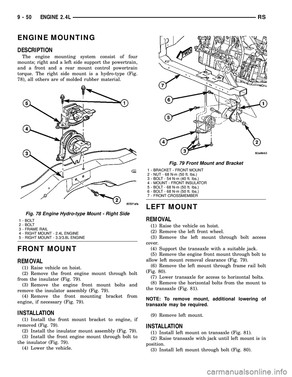
torque. The right side mount is a hydro-type (Fig.
78), all others are of molded rubber material.
FRONT MOUNT
REMOVAL
(1) Raise vehicle on hoist.
(2) Remove the front engine mount through bolt
from the insulator (Fig. 79).
(3) Remove the engine front mount bolts and
remove the insulator assembly (Fig. 79).
(4) Remove the front mounting bracket from
engine, if necessary (Fig. 79).
INSTALLATION
(1) Install the front mount bracket to engine, if
removed (Fig. 79).
(2) Install the insulator mount assembly (Fig. 79).
(3) Install the front engine mount through bolt to
the insulator (Fig. 79).
(4) Lower the vehicle.
LEFT MOUNT
REMOVAL
(1) Raise the vehicle on hoist.
(2) Remove the left front wheel.
(3) Remove the left mount through bolt access
cover.
(4) Support the transaxle with a suitable jack.
(5) Remove the engine front mount through bolt to
allow left mount removal clearance (Fig. 79).
(6) Remove the left mount through frame rail bolt
(Fig. 80).
(7) Lower transaxle for access to horizontal bolts.
(8) Remove the horizontal bolts from the mount to
the transaxle (Fig. 81).
NOTE: To remove mount, additional lowering of
transaxle may be required.
(9) Remove left mount.
INSTALLATION
(1) Install left mount on transaxle (Fig. 81).
(2) Raise transaxle with jack until left mount is in
position.
(3) Install left mount through bolt (Fig. 80).
Fig. 78 Engine Hydro-type Mount - Right Side
1 - BOLT
2 - BOLT
3 - FRAME RAIL
4 - RIGHT MOUNT - 2.4L ENGINE
5 - RIGHT MOUNT - 3.3/3.8L ENGINE
Fig. 79 Front Mount and Bracket
1 - BRACKET - FRONT MOUNT
2 - NUT - 68 N´m (50 ft. lbs.)
3 - BOLT - 54 N´m (40 ft. lbs.)
4 - MOUNT - FRONT INSULATOR
5 - BOLT - 68 N´m (50 ft. lbs.)
6 - BOLT - 68 N´m (50 ft. lbs.)
7 - FRONT CROSSMEMBER
9 - 50 ENGINE 2.4LRS
Page 1228 of 2339
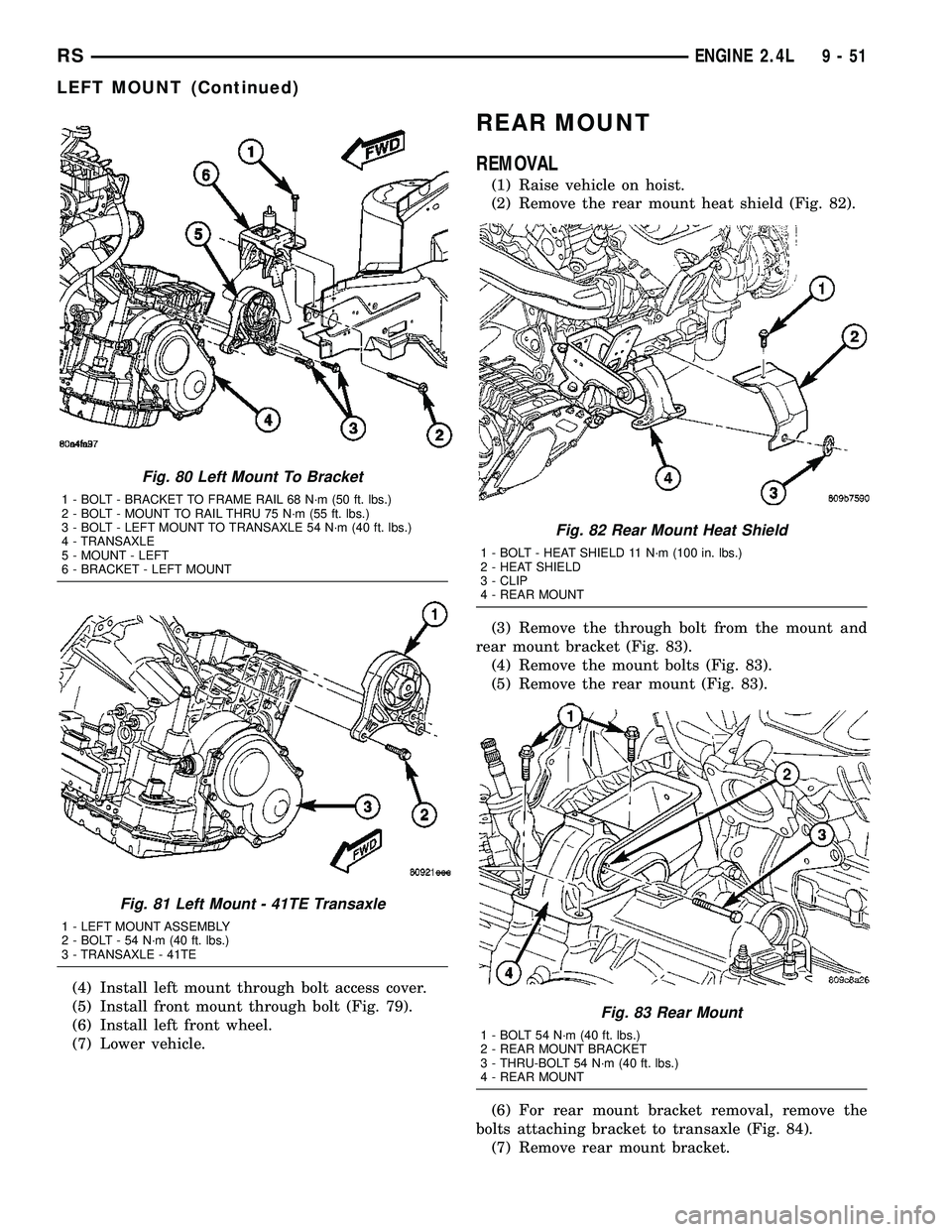
(4) Install left mount through bolt access cover.
(5) Install front mount through bolt (Fig. 79).
(6) Install left front wheel.
(7) Lower vehicle.
REAR MOUNT
REMOVAL
(1) Raise vehicle on hoist.
(2) Remove the rear mount heat shield (Fig. 82).
(3) Remove the through bolt from the mount and
rear mount bracket (Fig. 83).
(4) Remove the mount bolts (Fig. 83).
(5) Remove the rear mount (Fig. 83).
(6) For rear mount bracket removal, remove the
bolts attaching bracket to transaxle (Fig. 84).
(7) Remove rear mount bracket.
Fig. 80 Left Mount To Bracket
1 - BOLT - BRACKET TO FRAME RAIL 68 N´m (50 ft. lbs.)
2 - BOLT - MOUNT TO RAIL THRU 75 N´m (55 ft. lbs.)
3 - BOLT - LEFT MOUNT TO TRANSAXLE 54 N´m (40 ft. lbs.)
4 - TRANSAXLE
5 - MOUNT - LEFT
6 - BRACKET - LEFT MOUNT
Fig. 81 Left Mount - 41TE Transaxle
1 - LEFT MOUNT ASSEMBLY
2 - BOLT - 54 N´m (40 ft. lbs.)
3 - TRANSAXLE - 41TE
Fig. 82 Rear Mount Heat Shield
1 - BOLT - HEAT SHIELD 11 N´m (100 in. lbs.)
2 - HEAT SHIELD
3 - CLIP
4 - REAR MOUNT
Fig. 83 Rear Mount
1 - BOLT 54 N´m (40 ft. lbs.)
2 - REAR MOUNT BRACKET
3 - THRU-BOLT 54 N´m (40 ft. lbs.)
4 - REAR MOUNT
RSENGINE 2.4L9-51
LEFT MOUNT (Continued)
Page 1229 of 2339

INSTALLATION
(1) Install rear mount bracket, if removed (Fig.
84).
(2) Install the rear mount and bolts (Fig. 83).
Tighten bolts to 54 N´m (40 ft. lbs.).
(3) Install the mount through bolt to the mount
and bracket (Fig. 83). Tighten through bolt to 54 N´m
(40 ft. lbs.).
(4) Install the rear mount heat shield (Fig. 82).
(5) Lower vehicle on hoist.
RIGHT MOUNT
REMOVAL
(1) Remove air cleaner housing lid and clean air
hose from throttle body.
(2) Remove air cleaner element and housing.
(3) Disconnect make-up air hose from cylinder
head cover.
(4) Remove the load on the right engine mount by
carefully supporting the engine assembly with a floor
jack.
(5) Disconnect electrical harness support clips from
engine mount bracket.(6) Remove the vertical bolts attaching the engine
mount to the frame rail (Fig. 85).
(7) Loosen the horizontal bolt attaching the engine
mount to the frame rail (Fig. 85).
(8) Remove the bolts attaching the engine mount
to the engine bracket (Fig. 85).
(9) Remove the right engine mount (Fig. 85).
INSTALLATION
(1) Position right engine mount and install frame
rail to mount vertical bolts (Fig. 85).
(2) Tighten engine right mount to rail horizontal
bolt (Fig. 85).
(3) Install mount to engine bracket bolts (Fig. 85).
(4) Connect electrical harness support clips to
engine mount bracket.
(5) Remove jack from under engine.
(6) Connect make-up air hose to cylinder head
cover.
(7) Install air cleaner housing and element.
(8) Install air cleaner housing lid and clean air
tube to throttle body.
Fig. 84 Rear Mount Bracket - (all engines)
1 - BOLT - VERTICAL 102 N´m (75 ft. lbs.)
2 - BRACKET - REAR MOUNT3 - BOLT - HORIZONTAL 102 N´m (75 ft. lbs.)
9 - 52 ENGINE 2.4LRS
REAR MOUNT (Continued)