Frame CHRYSLER VOYAGER 2005 User Guide
[x] Cancel search | Manufacturer: CHRYSLER, Model Year: 2005, Model line: VOYAGER, Model: CHRYSLER VOYAGER 2005Pages: 2339, PDF Size: 59.69 MB
Page 86 of 2339
(2) Remove the bolts securing the stabilizer bar to
links on each end of the bar.
(3) While holding the stabilizer bar in place,
remove the bolts that attach the stabilizer bar bush-
ing retainers to the rear axle.
(4) Remove the stabilizer bar from the vehicle.
(5) If the links need to be serviced, remove the
upper link arm to bracket bolt. Then remove link
arm from frame rail attaching bracket.
REMOVAL - FWD
(1) Raise vehicle. See Hoisting in Lubrication and
Maintenance.
(2) Remove the bolts securing the stabilizer bar to
links on each side of bar.
(3) While holding the stabilizer bar in place,
remove the bolts that attach the stabilizer bar bush-
ing retainers to the rear axle.
(4) Remove the stabilizer bar from the vehicle.
REMOVAL - FWD - FOLD-IN-FLOOR SEATING
(1) Raise and support vehicle. (Refer to LUBRICA-
TION & MAINTENANCE/HOISTING - STANDARD
PROCEDURE)
(2) At each end of the stabilizer bar, remove the
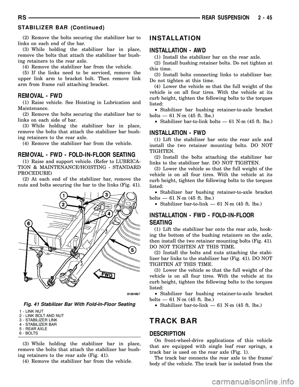
nuts and bolts securing the bar to the links (Fig. 41).
(3) While holding the stabilizer bar in place,
remove the bolts that attach the stabilizer bar bush-
ing retainers to the rear axle (Fig. 41).
(4) Remove the stabilizer bar from the vehicle.
INSTALLATION
INSTALLATION - AWD
(1) Install the stabilizer bar on the rear axle.
(2) Install bushing retainer bolts. Do not tighten at
this time.
(3) Install bolts connecting links to stabilizer bar.
Do not tighten at this time.
(4) Lower the vehicle so that the full weight of the
vehicle is on all four tires. With the vehicle at its
curb height, tighten the following bolts to the torques
listed:
²Stabilizer bar bushing retainer-to-axle bracket
bolts Ð 61 N´m (45 ft. lbs.)
²Stabilizer bar-to-link bolts Ð 61 N´m (45 ft. lbs.)
INSTALLATION - FWD
(1) Lift the stabilizer bar onto the rear axle and
install the two retainer mounting bolts. DO NOT
TIGHTEN.
(2) Install the bolts attaching the stabilizer bar
links to the stabilizer bar. DO NOT TIGHTEN.
(3) Lower the vehicle so that the full weight of the
vehicle is on all four tires. With the vehicle at its
curb height, tighten the following bolts to the torques
listed:
²Stabilizer bar bushing retainer-to-axle bracket
bolts Ð 61 N´m (45 ft. lbs.)
²Stabilizer bar-to-link Ð 61 N´m (45 ft. lbs.)
INSTALLATION - FWD - FOLD-IN-FLOOR
SEATING
(1) Lift the stabilizer bar onto the rear axle, hook-
ing the bottom of the bushing retainers on the axle,
then install the two retainer mounting bolts (Fig. 41).
DO NOT TIGHTEN AT THIS TIME.
(2) Install the bolts and nuts attaching the stabi-
lizer bar links to the stabilizer bar (Fig. 41). DO NOT
TIGHTEN AT THIS TIME.
(3) Lower the vehicle so that the full weight of the
vehicle is on all four tires. With the vehicle at its
curb height, tighten the following bolts to the torques
listed:
²Stabilizer bar bushing retainer-to-axle bracket
bolts Ð 61 N´m (45 ft. lbs.)
²Stabilizer bar-to-link Ð 61 N´m (45 ft. lbs.)
TRACK BAR
DESCRIPTION
On front-wheel-drive applications of this vehicle
that are equipped with single leaf rear springs, a
track bar is used on the rear axle (Fig. 1).
The track bar connects the rear axle to the frame/
body of the vehicle. The track bar is isolated from the
Fig. 41 Stabilizer Bar With Fold-In-Floor Seating
1 - LINK NUT
2 - LINK BOLT AND NUT
3 - STABILIZER LINK
4 - STABILIZER BAR
5 - REAR AXLE
6 - BOLTS
RSREAR SUSPENSION2-45
STABILIZER BAR (Continued)
Page 87 of 2339
body of the vehicle by an isolator bushing located in
each end of the track bar.
OPERATION
The track bar prevents excessive side-to-side move-
ment of the rear axle. The track bar is used to keep
the location of the axle in the correct position for
optimum handling and control of the vehicle.
REMOVAL
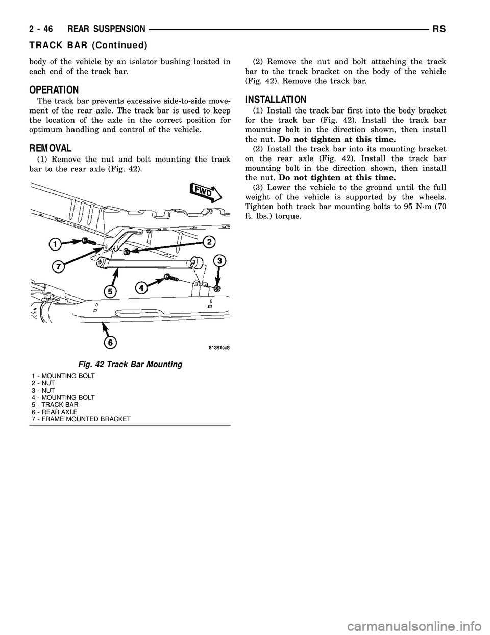
(1) Remove the nut and bolt mounting the track
bar to the rear axle (Fig. 42).(2) Remove the nut and bolt attaching the track
bar to the track bracket on the body of the vehicle
(Fig. 42). Remove the track bar.
INSTALLATION
(1) Install the track bar first into the body bracket
for the track bar (Fig. 42). Install the track bar
mounting bolt in the direction shown, then install
the nut.Do not tighten at this time.
(2) Install the track bar into its mounting bracket
on the rear axle (Fig. 42). Install the track bar
mounting bolt in the direction shown, then install
the nut.Do not tighten at this time.
(3) Lower the vehicle to the ground until the full
weight of the vehicle is supported by the wheels.
Tighten both track bar mounting bolts to 95 N´m (70
ft. lbs.) torque.
Fig. 42 Track Bar Mounting
1 - MOUNTING BOLT
2 - NUT
3 - NUT
4 - MOUNTING BOLT
5 - TRACK BAR
6 - REAR AXLE
7 - FRAME MOUNTED BRACKET
2 - 46 REAR SUSPENSIONRS
TRACK BAR (Continued)
Page 90 of 2339

TOE-OUT ON TURNS
Toe-out on turns is the relative positioning of the
front wheels while steering through a turn (Fig. 4).
This compensates for each front wheel's turning
radius. As the vehicle encounters a turn, the out-
board wheel must travel in a larger radius circle
than the inboard wheel. The steering system is
designed to make each wheel follow its particular
radius circle. To accomplish this, the front wheels
must progressively toe outward as the steering is
turned from center. This eliminates tire scrubbing
and undue tire wear when steering a vehicle through
a turn.
DYNAMIC TOE PATTERN
Dynamic toe pattern is the inward and outward toe
movement of the front and rear tires through the
suspension's jounce and rebound travel. As the vehi-
cle's suspension moves up and down, the toe pattern
varies. Toe pattern is critical in controlling the direc-
tional stability of the vehicle while in motion. Front
and rear dynamic toe pattern is preset by the factory
at the time the vehicle is assembled.
It is not necessary to check or adjust front or rear
dynamic toe pattern when doing a normal wheel
alignment. The only time dynamic toe pattern needs
to be checked or adjusted is if the frame of the vehi-
cle has been damaged.
STEERING AXIS INCLINATION (S. A. I.)
Steering axis inclination is the angle between a
true vertical line starting at the center of the tire at
the road contact point and a line drawn through the
center of the upper ball joint (or strut) and the lower
ball joint (Fig. 5). S.A.I. is built into the vehicle and
is not an adjustable angle. If S.A.I. is not within
specifications, a bent or damaged suspension compo-
nent may be the cause.
INCLUDED ANGLE (I. A.)
Included angle is the sum of the S.A.I. angle plus
or minus the camber angle, depending on whether or
not the wheel has positive or negative camber (Fig.
5). If camber is positive, add the camber angle to the
S.A.I. angle. If camber is negative, subtract the cam-
ber angle from the S.A.I. angle. Included angle is not
adjustable, but can be used to diagnose a frame mis-
alignment or bent suspension component (spindle,
strut).
Fig. 4 Toe-Out On Turns
1 - TOE-OUT ON TURNS
Fig. 5 S.A.I. and I.A.
1 - S.A.I.
2 - CAMBER
3 - I.A.
RSWHEEL ALIGNMENT2-49
WHEEL ALIGNMENT (Continued)
Page 91 of 2339
THRUST ANGLE
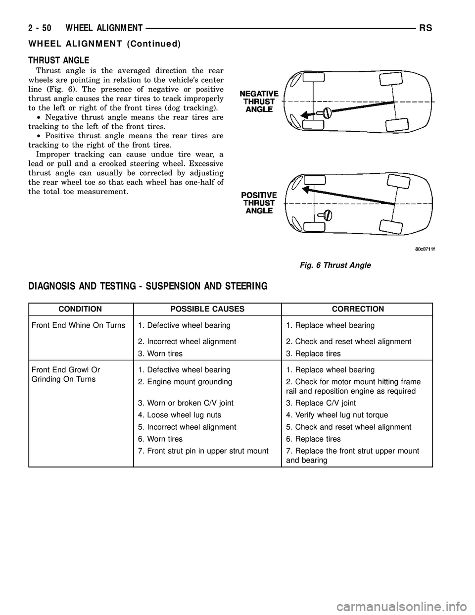
Thrust angle is the averaged direction the rear
wheels are pointing in relation to the vehicle's center
line (Fig. 6). The presence of negative or positive
thrust angle causes the rear tires to track improperly
to the left or right of the front tires (dog tracking).
²Negative thrust angle means the rear tires are
tracking to the left of the front tires.
²Positive thrust angle means the rear tires are
tracking to the right of the front tires.
Improper tracking can cause undue tire wear, a
lead or pull and a crooked steering wheel. Excessive
thrust angle can usually be corrected by adjusting
the rear wheel toe so that each wheel has one-half of
the total toe measurement.
DIAGNOSIS AND TESTING - SUSPENSION AND STEERING
CONDITION POSSIBLE CAUSES CORRECTION
Front End Whine On Turns 1. Defective wheel bearing 1. Replace wheel bearing
2. Incorrect wheel alignment 2. Check and reset wheel alignment
3. Worn tires 3. Replace tires
Front End Growl Or
Grinding On Turns1. Defective wheel bearing 1. Replace wheel bearing
2. Engine mount grounding 2. Check for motor mount hitting frame
rail and reposition engine as required
3. Worn or broken C/V joint 3. Replace C/V joint
4. Loose wheel lug nuts 4. Verify wheel lug nut torque
5. Incorrect wheel alignment 5. Check and reset wheel alignment
6. Worn tires 6. Replace tires
7. Front strut pin in upper strut mount 7. Replace the front strut upper mount
and bearing
Fig. 6 Thrust Angle
2 - 50 WHEEL ALIGNMENTRS
WHEEL ALIGNMENT (Continued)
Page 170 of 2339

Minimum allowable thickness is the minimum
thickness which the brake rotor machined surface
may be cut to.
CAUTION: Do not machine the rotor if it will cause
the rotor to fall below minimum thickness.
Before installation, verify the brake rotor face and
the hub adapters are free of any chips, rust, or con-
tamination.
When mounting and using the brake lathe, strict
attention to the brake lathe manufacturer's operating
instructions is required.
Machine both sides of the brake rotor at the same
time. Cutting both sides at the same time minimizes
the possibility of a tapered or uneven cut.
When refacing a rotor, the required TIR (Total
Indicator Reading) and thickness variation limits
MUST BE MAINTAINED. Extreme care in the oper-
ation of rotor turning equipment is required. Specifi-
cations for brake rotor machining can be found in
this section's specification table. (Refer to 5 -
BRAKES/HYDRAULIC/MECHANICAL/ROTOR -
SPECIFICATIONS)
REMOVAL - FRONT BRAKE ROTOR
(1) Raise vehicle on jackstands or centered on a
frame contact type hoist. See Hoisting in Lubrication
and Maintenance.
(2) Remove the front wheel and tire assembly.
(3) Remove the two mounting bolts securing the
disc brake caliper adapter with brake caliper to the
steering knuckle (Fig. 91).
(4) Remove the disc brake caliper and adapter as
an assembly from the steering knuckle (Fig. 91).
Hang the assembly out of the way using wire or a
bungee cord. Use care not to overextend the brake
hose when doing this.
(5) Remove any retainer clips from the wheel
mounting studs.
(6) Remove brake rotor from hub by pulling it
straight off wheel mounting studs (Fig. 91).
INSTALLATION - FRONT BRAKE ROTOR
(1) Install the brake rotor back on the hub and
bearing (Fig. 91).(2) Install brake caliper and adapter back over
brake rotor aligning adapter with mounting holes on
steering knuckle (Fig. 91).
(3) Install the two adapter mounting bolts securing
the adapter to the steering knuckle. Tighten the
mounting bolts to 169 N´m (125 ft. lbs.) torque.
(4) Install wheel and tire assembly on vehicle.
Tighten the wheel mounting lug nuts in proper
sequence until all nuts are torqued to half specifica-
tion, then repeat the tightening sequence to the full
specified torque of 135 N´m (100 ft. lbs.).
(5) Lower vehicle to the ground.
Fig. 91 Front Brake Mounting
1 - BRAKE ROTOR
2 - HUB AND BEARING
3 - STEERING KNUCKLE
4 - ADAPTER MOUNTING BOLTS
5 - BRAKE CALIPER
6 - ADAPTER
7 - CLIP
RSBRAKES - BASE5-59
ROTOR (Continued)
Page 180 of 2339
CABLE - PARKING BRAKE
INTERMEDIATE
REMOVAL
(1) Raise and support the vehicle. (Refer to
LUBRICATION & MAINTENANCE/HOISTING -
STANDARD PROCEDURE).
(2) Manually lock out the automatic self-adjusting
mechanism tension of the parking brake lever (pedal)
assembly. (Refer to 5 - BRAKES - STANDARD PRO-
CEDURE). Once the cable is released from the equal-
izer, do not remove the locking pliers until
reinstallation of the cable is complete.
(3) Remove the intermediate parking brake cable
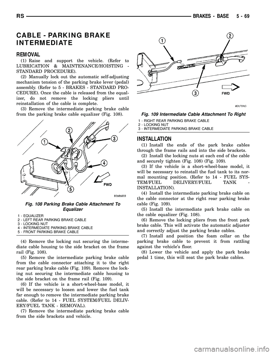
from the parking brake cable equalizer (Fig. 108).
(4) Remove the locking nut securing the interme-
diate cable housing to the side bracket on the frame
rail (Fig. 108).
(5) Remove the intermediate parking brake cable
from the cable connector attaching it to the right
rear parking brake cable (Fig. 109). Remove the lock-
ing nut securing the intermediate cable housing to
the side bracket on the frame rail (Fig. 109).
(6) If the vehicle is a short-wheel-base model, it
will be necessary to loosen and lower the fuel tank
far enough to remove the intermediate parking brake
cable. (Refer to 14 - FUEL SYSTEM/FUEL DELIV-
ERY/FUEL TANK - REMOVAL).
(7) Remove the intermediate parking brake cable
from the side brackets and vehicle.
INSTALLATION
(1) Install the ends of the park brake cables
through the frame rails and into the side brackets.
(2) Install the locking nuts at each end of the cable
and securely tighten (Fig. 108) (Fig. 109).
(3) If the vehicle is a short-wheel-base model, it
will be necessary to reinstall the fuel tank to its nor-
mal mounting position. (Refer to 14 - FUEL SYS-
TEM/FUEL DELIVERY/FUEL TANK -
INSTALLATION).
(4) Install the intermediate parking brake cable on
the cable connector at the right rear parking brake
cable (Fig. 109).
(5) Install the intermediate park brake cable on
the cable equalizer (Fig. 108).
(6) Remove the locking pliers from the front park
brake cable. This will activate the automatic adjuster
and correctly adjust the parking brake cables.
(7) Install and position the foam collar on the
parking brake cable to prevent it from rattling
against the vehicle's floor.
(8) Lower the vehicle and apply the park brake
pedal 1 time, this will seat the park brake cables.
Fig. 108 Parking Brake Cable Attachment To
Equalizer
1 - EQUALIZER
2 - LEFT REAR PARKING BRAKE CABLE
3 - LOCKING NUT
4 - INTERMEDIATE PARKING BRAKE CABLE
5 - FRONT PARKING BRAKE CABLE
Fig. 109 Intermediate Cable Attachment To Right
1 - RIGHT REAR PARKING BRAKE CABLE
2 - LOCKING NUT
3 - INTERMEDIATE PARKING BRAKE CABLE
RSBRAKES - BASE5-69
Page 239 of 2339
COOLANT RECOVERY
CONTAINER
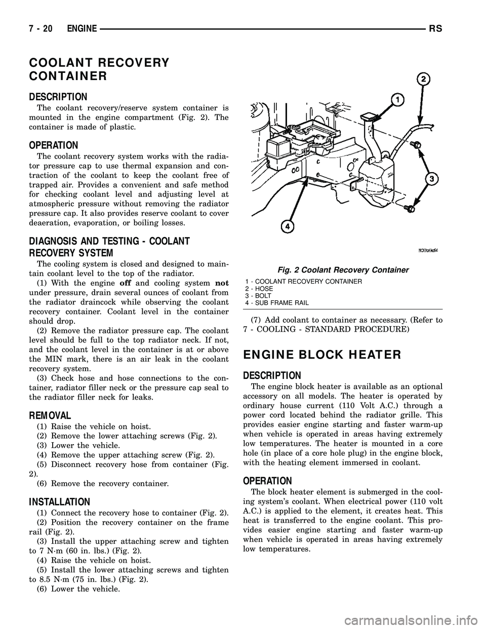
DESCRIPTION
The coolant recovery/reserve system container is
mounted in the engine compartment (Fig. 2). The
container is made of plastic.
OPERATION
The coolant recovery system works with the radia-
tor pressure cap to use thermal expansion and con-
traction of the coolant to keep the coolant free of
trapped air. Provides a convenient and safe method
for checking coolant level and adjusting level at
atmospheric pressure without removing the radiator
pressure cap. It also provides reserve coolant to cover
deaeration, evaporation, or boiling losses.
DIAGNOSIS AND TESTING - COOLANT
RECOVERY SYSTEM
The cooling system is closed and designed to main-
tain coolant level to the top of the radiator.
(1) With the engineoffand cooling systemnot
under pressure, drain several ounces of coolant from
the radiator draincock while observing the coolant
recovery container. Coolant level in the container
should drop.
(2) Remove the radiator pressure cap. The coolant
level should be full to the top radiator neck. If not,
and the coolant level in the container is at or above
the MIN mark, there is an air leak in the coolant
recovery system.
(3) Check hose and hose connections to the con-
tainer, radiator filler neck or the pressure cap seal to
the radiator filler neck for leaks.
REMOVAL
(1) Raise the vehicle on hoist.
(2) Remove the lower attaching screws (Fig. 2).
(3) Lower the vehicle.
(4) Remove the upper attaching screw (Fig. 2).
(5) Disconnect recovery hose from container (Fig.
2).
(6) Remove the recovery container.
INSTALLATION
(1) Connect the recovery hose to container (Fig. 2).
(2) Position the recovery container on the frame
rail (Fig. 2).
(3) Install the upper attaching screw and tighten
to 7 N´m (60 in. lbs.) (Fig. 2).
(4) Raise the vehicle on hoist.
(5) Install the lower attaching screws and tighten
to 8.5 N´m (75 in. lbs.) (Fig. 2).
(6) Lower the vehicle.(7) Add coolant to container as necessary. (Refer to
7 - COOLING - STANDARD PROCEDURE)
ENGINE BLOCK HEATER
DESCRIPTION
The engine block heater is available as an optional
accessory on all models. The heater is operated by
ordinary house current (110 Volt A.C.) through a
power cord located behind the radiator grille. This
provides easier engine starting and faster warm-up
when vehicle is operated in areas having extremely
low temperatures. The heater is mounted in a core
hole (in place of a core hole plug) in the engine block,
with the heating element immersed in coolant.
OPERATION
The block heater element is submerged in the cool-
ing system's coolant. When electrical power (110 volt
A.C.) is applied to the element, it creates heat. This
heat is transferred to the engine coolant. This pro-
vides easier engine starting and faster warm-up
when vehicle is operated in areas having extremely
low temperatures.
Fig. 2 Coolant Recovery Container
1 - COOLANT RECOVERY CONTAINER
2 - HOSE
3 - BOLT
4 - SUB FRAME RAIL
7 - 20 ENGINERS
Page 285 of 2339
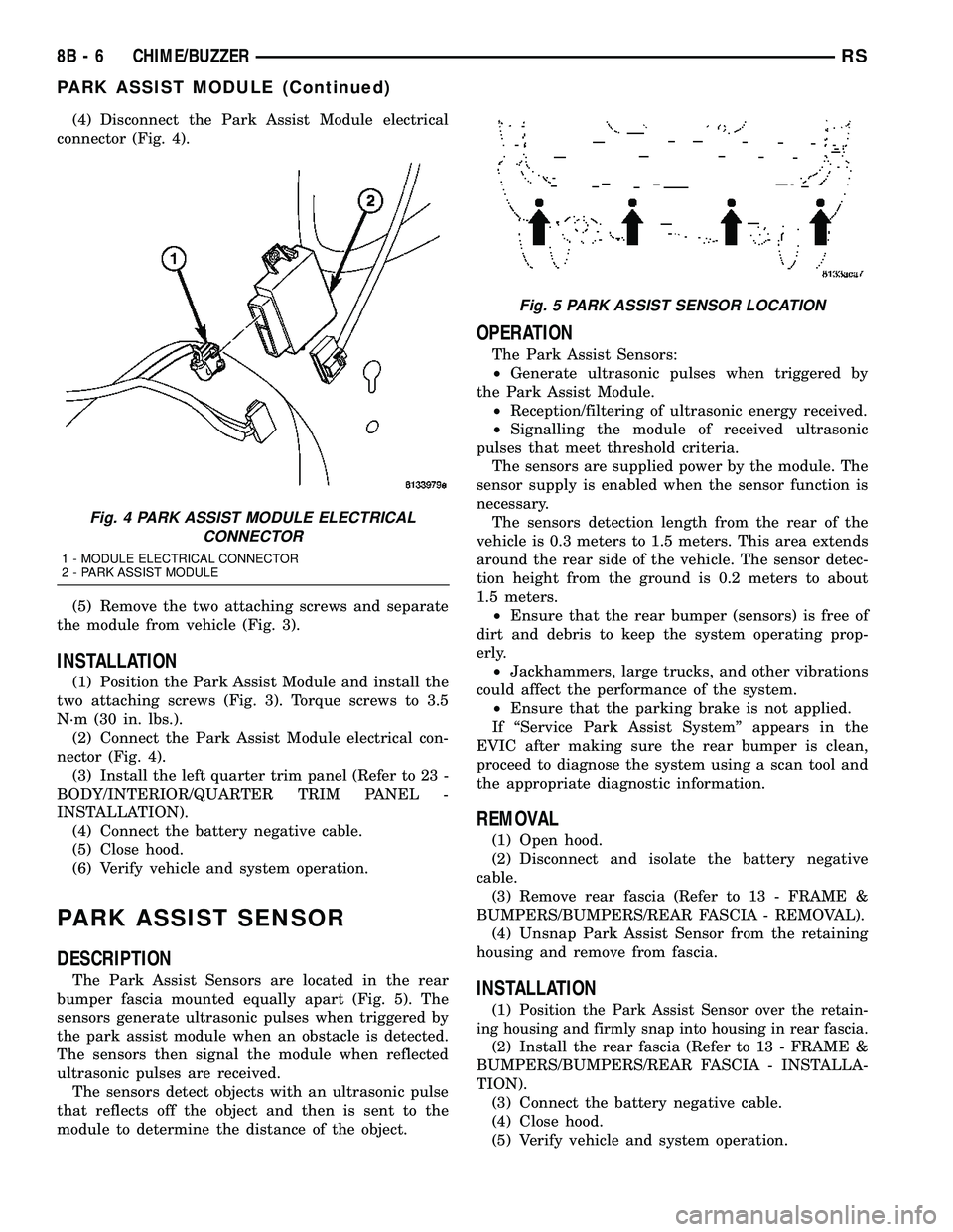
(4) Disconnect the Park Assist Module electrical
connector (Fig. 4).
(5) Remove the two attaching screws and separate
the module from vehicle (Fig. 3).
INSTALLATION
(1) Position the Park Assist Module and install the
two attaching screws (Fig. 3). Torque screws to 3.5
N´m (30 in. lbs.).
(2) Connect the Park Assist Module electrical con-
nector (Fig. 4).
(3) Install the left quarter trim panel (Refer to 23 -
BODY/INTERIOR/QUARTER TRIM PANEL -
INSTALLATION).
(4) Connect the battery negative cable.
(5) Close hood.
(6) Verify vehicle and system operation.
PARK ASSIST SENSOR
DESCRIPTION
The Park Assist Sensors are located in the rear
bumper fascia mounted equally apart (Fig. 5). The
sensors generate ultrasonic pulses when triggered by
the park assist module when an obstacle is detected.
The sensors then signal the module when reflected
ultrasonic pulses are received.
The sensors detect objects with an ultrasonic pulse
that reflects off the object and then is sent to the
module to determine the distance of the object.
OPERATION
The Park Assist Sensors:
²Generate ultrasonic pulses when triggered by
the Park Assist Module.
²Reception/filtering of ultrasonic energy received.
²Signalling the module of received ultrasonic
pulses that meet threshold criteria.
The sensors are supplied power by the module. The
sensor supply is enabled when the sensor function is
necessary.
The sensors detection length from the rear of the
vehicle is 0.3 meters to 1.5 meters. This area extends
around the rear side of the vehicle. The sensor detec-
tion height from the ground is 0.2 meters to about
1.5 meters.
²Ensure that the rear bumper (sensors) is free of
dirt and debris to keep the system operating prop-
erly.
²Jackhammers, large trucks, and other vibrations
could affect the performance of the system.
²Ensure that the parking brake is not applied.
If ªService Park Assist Systemº appears in the
EVIC after making sure the rear bumper is clean,
proceed to diagnose the system using a scan tool and
the appropriate diagnostic information.
REMOVAL
(1) Open hood.
(2) Disconnect and isolate the battery negative
cable.
(3) Remove rear fascia (Refer to 13 - FRAME &
BUMPERS/BUMPERS/REAR FASCIA - REMOVAL).
(4) Unsnap Park Assist Sensor from the retaining
housing and remove from fascia.
INSTALLATION
(1)Position the Park Assist Sensor over the retain-
ing housing and firmly snap into housing in rear fascia.
(2) Install the rear fascia (Refer to 13 - FRAME &
BUMPERS/BUMPERS/REAR FASCIA - INSTALLA-
TION).
(3) Connect the battery negative cable.
(4) Close hood.
(5) Verify vehicle and system operation.
Fig. 4 PARK ASSIST MODULE ELECTRICAL
CONNECTOR
1 - MODULE ELECTRICAL CONNECTOR
2 - PARK ASSIST MODULE
Fig. 5 PARK ASSIST SENSOR LOCATION
8B - 6 CHIME/BUZZERRS
PARK ASSIST MODULE (Continued)
Page 300 of 2339
The power grounds are used to control the ground
side relays, solenoids, ignition coil or injectors. The
signal ground is used for any input that uses sensor
return for ground, and the ground side of any inter-
nal processing component.
The PCM case is shielded to prevent RFI and EMI.
The PCM case is grounded and must be firmly
attached to a good, clean body ground.
Internally all grounds are connected together, how-
ever there is noise suppression on the sensor ground.
For EMI and RFI protection the housing and cover
are also grounded separately from the ground pins.
OPERATION - 5 VOLT SUPPLY - PCM OUTPUT
The PCM supplies 5 volts to the following sensors:
²A/C pressure transducer
²Ambient Temperature sensor
²Battery temperature
²Camshaft Position Sensor (NGC)
²Crankshaft Position Sensor (NGC)
²Engine coolant temperature sensor
²Inlet Air Temperature Sensor
²Knock sensor
²Linear EGR solenoid (if equipped)
²Manifold absolute pressure sensor
²Oil Pressure Switch
²Throttle position sensor
STANDARD PROCEDURE
STANDARD PROCEDURE - OBTAINING
DIAGNOSTIC TROUBLE CODES
BULB CHECK
Key on: Bulb illuminated until vehicle starts, as
long as all once per trip (readiness) monitors com-
pleted. If monitors havenotbeen completed, then:
Key on: bulb check for about 5 to 8 seconds, lamp
then flashes if once per trip (readiness) monitors
havenotbeen completed until vehicle is started,
then MIL is extinguished.
OBTAINING DTC'S USING DRB SCAN TOOL
(1) Connect the DRB scan tool to the data link
(diagnostic) connector. This connector is located in
the passenger compartment; at the lower edge of
instrument panel; near the steering column.
(2) Turn the ignition switch on and access the
ªRead Faultº screen.
(3) Record all the DTC's and ªfreeze frameº infor-
mation shown on the DRB scan tool.
(4) To erase DTC's, use the ªErase Trouble Codeº
data screen on the DRB scan tool.Do not erase any
DTC's until problems have been investigated
and repairs have been performed.
STANDARD PROCEDURE - PINION FACTOR
SETTING
NOTE: This procedure must be performed if the
PCM has been replaced with a NEW or replacement
unit. Failure to perform this procedure will result in
an inoperative or improperly calibrated speedome-
ter.
The vehicle speed readings for the speedometer are
taken from the output speed sensor. The PCM must
be calibrated to the different combinations of equip-
ment (final drive and tires) available. Pinion Factor
allows the technician to set the Powertrain Control
Module initial setting so that the speedometer read-
ings will be correct. To properly read and/or reset the
Pinion Factor, it is necessary to use a DRBIIItscan
tool.
(1) Plug the DRBIIItscan tool into the diagnostic
connector located under the instrument panel.
(2) Select the Transmission menu.
(3) Select the Miscellaneous menu.
(4) Select Pinion Factor. Then follow the instruc-
tions on the DRBIIItscan tool screen.
STANDARD PROCEDURE - QUICK LEARN
PROCEDURE
The quick learn procedure requires the use of the
DRBIIItscan tool. This program allows the PCM to
recalibrate itself. This will provide the best possible
transaxle operation.
NOTE: The quick learn procedure should be per-
formed if any of the following procedures are per-
formed:
²Transaxle Assembly Replacement
²Powertrain Control Module Replacement
²Solenoid/Pressure Switch Assembly Replacement
²Clutch Plate and/or Seal Replacement
²Valve Body Replacement or Recondition
To perform the Quick Learn Procedure, the follow-
ing conditions must be met:
²The brakes must be applied
²The engine speed must be above 500 rpm
²The throttle angle (TPS) must be less than 3
degrees
²The shift lever position must stay until
prompted to shift to overdrive
²The shift lever position must stay in overdrive
after the Shift to Overdrive prompt until the
DRBIIItindicates the procedure is complete
²The calculated oil temperature must be above
60É and below 200É
RSELECTRONIC CONTROL MODULES8E-15
POWERTRAIN CONTROL MODULE (Continued)
Page 313 of 2339

CONVENTIONAL BATTERY - GASOLINE ENGINE
Low-maintenance batteriesare used on export
vehicles equipped with a gasoline engine, these bat-
teries have removable battery cell caps (Fig. 5).
Watercanbe added to this battery. Under normal
service, the composition of this battery reduces gas-
sing and water loss at normal charge rates. However
these batteries may require additional distilled water
after years of service.
Maintenance-free batteriesare standard facto-
ry-installed equipment on all domestic vehicles. Male
post type terminals made of a soft lead material pro-
trude from the top of the molded plastic battery case
(Fig. 6)to provide the means for connecting the bat-
tery to the vehicle electrical system. The battery pos-
itive terminal post is visibly larger in diameter than
the negative terminal post, for easy identification.
The lettersPOSandNEGare also molded into the
top of the battery case adjacent to their respective
positive and negative terminal posts for additional
identification confirmation.
This battery is designed to provide a safe, efficient
and reliable means of storing electrical energy in a
chemical form. This means of energy storage allows
the battery to produce the electrical energy required
to operate the engine starting system, as well as to
operate many of the other vehicle accessory systems
for limited durations while the engine and/or thecharging system are not operating. The battery is
made up of six individual cells that are connected in
series. Each cell contains positively charged plate
groups that are connected with lead straps to the
positive terminal post, and negatively charged plate
groups that are connected with lead straps to the
negative terminal post. Each plate consists of a stiff
mesh framework or grid coated with lead dioxide
(positive plate) or sponge lead (negative plate). Insu-
lators or plate separators made of a non-conductive
material are inserted between the positive and nega-
tive plates to prevent them from contacting or short-
ing against one another. These dissimilar metal
plates are submerged in a sulfuric acid and water
solution called an electrolyte.
Some factory-installed batteries have a built-in test
indicator (hydrometer). The color visible in the sight
glass of the indicator will reveal the battery condi-
tion. For more information on the use of the built-in
test indicator, refer toStandard Procedures. The
chemical composition of the metal coated plates
within the low-maintenance battery used in export
models reduces battery gassing and water loss at
normal charge and discharge rates. Therefore, the
battery should not require additional water in nor-
mal service. If the electrolyte level in this battery
does become low, distilled water must be added. How-
ever, rapid loss of electrolyte can be caused by an
overcharging condition. Be certain to diagnose the
charging system after replenishing the water in the
Fig. 5 BATTERY CELL CAP REMOVAL/
INSTALLATION - LOW-MAINTANANCE GASOLINE
ENGINE BATTERY - EXPORT
1 - BATTERY CELL CAP
2 - BATTERY CASE
Fig. 6 Maintenance-Free Battery - Domestic
1 - POSITIVE POST
2 - VENT
3 - CELL CAP
4 - VENT
5 - CELL CAP
6 - VENT
7 - NEGATIVE POST
8 - INDICATOR EYE (if equipped)
9 - ELECTROLYTE LEVEL
10 - PLATE GROUPS
11 - MAINTENANCE-FREE BATTERY
8F - 8 BATTERY SYSTEMRS
BATTERY (Continued)