rear lamp CHRYSLER VOYAGER 2005 Workshop Manual
[x] Cancel search | Manufacturer: CHRYSLER, Model Year: 2005, Model line: VOYAGER, Model: CHRYSLER VOYAGER 2005Pages: 2339, PDF Size: 59.69 MB
Page 351 of 2339
HEATED MIRRORS
TABLE OF CONTENTS
page page
HEATED MIRRORS
DESCRIPTION..........................6OPERATION............................6
HEATED MIRRORS
DESCRIPTION
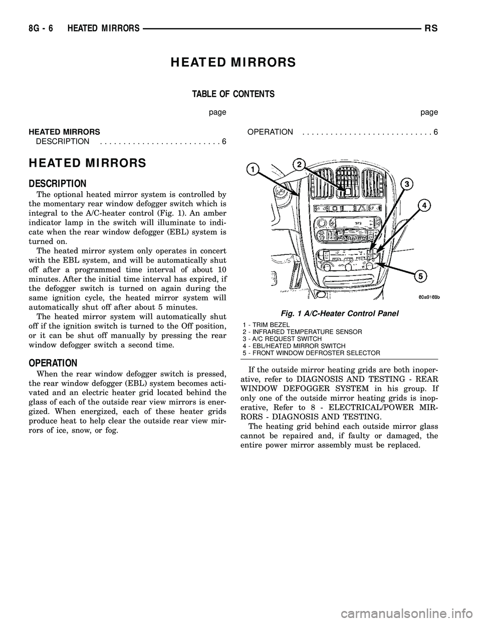
The optional heated mirror system is controlled by
the momentary rear window defogger switch which is
integral to the A/C-heater control (Fig. 1). An amber
indicator lamp in the switch will illuminate to indi-
cate when the rear window defogger (EBL) system is
turned on.
The heated mirror system only operates in concert
with the EBL system, and will be automatically shut
off after a programmed time interval of about 10
minutes. After the initial time interval has expired, if
the defogger switch is turned on again during the
same ignition cycle, the heated mirror system will
automatically shut off after about 5 minutes.
The heated mirror system will automatically shut
off if the ignition switch is turned to the Off position,
or it can be shut off manually by pressing the rear
window defogger switch a second time.
OPERATION
When the rear window defogger switch is pressed,
the rear window defogger (EBL) system becomes acti-
vated and an electric heater grid located behind the
glass of each of the outside rear view mirrors is ener-
gized. When energized, each of these heater grids
produce heat to help clear the outside rear view mir-
rors of ice, snow, or fog.If the outside mirror heating grids are both inoper-
ative, refer to DIAGNOSIS AND TESTING - REAR
WINDOW DEFOGGER SYSTEM in his group. If
only one of the outside mirror heating grids is inop-
erative, Refer to 8 - ELECTRICAL/POWER MIR-
RORS - DIAGNOSIS AND TESTING.
The heating grid behind each outside mirror glass
cannot be repaired and, if faulty or damaged, the
entire power mirror assembly must be replaced.
Fig. 1 A/C-Heater Control Panel
1 - TRIM BEZEL
2 - INFRARED TEMPERATURE SENSOR
3 - A/C REQUEST SWITCH
4 - EBL/HEATED MIRROR SWITCH
5 - FRONT WINDOW DEFROSTER SELECTOR
8G - 6 HEATED MIRRORSRS
Page 374 of 2339
INSTRUMENT CLUSTER
TABLE OF CONTENTS
page page
INSTRUMENT CLUSTER
DESCRIPTION..........................1
OPERATION............................1
DIAGNOSIS AND TESTING
DIAGNOSIS AND TESTING - SELF-
DIAGNOSTICS.........................2
DIAGNOSIS AND TESTING - CLUSTER
DIAGNOSIS...........................3REMOVAL.............................11
INSTALLATION.........................11
CLUSTER LENS
REMOVAL.............................11
INSTALLATION.........................11
INSTRUMENT CLUSTER
DESCRIPTION
The instrumentation gauges are contained in a
subdial assembly within the instrument cluster. The
individual gauges are not serviceable. If one of the
cluster gauges becomes faulty, the entire cluster
would require replacement.
The Mechanical Instrument Cluster (MIC) with a
tachometer is equipped with a electronic vacuum flu-
orescent transmission range indicator (PRND3L),
odometer, and trip odometer display.
The MIC without a tachometer is equipped with a
Light Emitting Diode (LED) transmission range indi-
cator (PRND3L) and a vacuum fluorescent odometer
display.
The MIC is equipped with the following warning
lamps.
²Lift Gate Ajar
²Low Fuel Level
²Low Windshield Washer Fluid Level
²Cruise
²Battery Voltage
²Fasten Seat Belt
²Door Ajar
²Coolant Temperature
²Anti-Lock Brake
²Brake
²Oil Pressure
²MIL (Malfunction Indicator Lamp)
²VTSS/SKIS Indicator
²Airbag
²Traction Control
²Autostick
Export Only- uses a message center that displays
the following telltales:
²Turns Signals
²High Beam
²Tire Pressure Monitoring (TPM)²Glow Plug (Export Only)
²Supplemental Cabin Heater (Export Only)WATER IN FUEL LAMP - EXPORT
The Water In Fuel Lamp is located in the message
center. When moisture is found within the fuel sys-
tem, the sensor sends a message via the PCI data
bus to the instrument cluster. The MIC illuminates
the bulb in the message center, The sensor is located
underneath the vehicle, directly above the rear axle.
The sensor is housed within the fuel filter/water sep-
arator assembly cover. The sensor is not serviced sep-
arately. If found defective, the entire assembly cover
must be replaced.
OPERATION
Refer to the vehicle Owner's Manual for operation
instructions and conditions for the Instrument Clus-
ter Gauges.
WATER IN FUEL LAMP/SENSOR - EXPORT
The Water In Fuel Sensor is a resistive type
switch. It is calibrated to sense the different resis-
tance between diesel fuel and water. When water
enters the fuel system, it is caught in the bottom of
the fuel filter/water separator assembly, where the
sensor is located. Water has less resistance than die-
sel fuel. The sensor then sends a PCI data bus mes-
sage to the instrument cluster to illuminate the
lamp.
If the lamp is inoperative, perform the self diag-
nostic test on the instrument cluster to check the
lamp operation before continuing diagnosis.
RSINSTRUMENT CLUSTER8J-1
Page 387 of 2339
LAMPS/LIGHTING - EXTERIOR
DESCRIPTION
LAMP SYSTEMS
Lighting circuits are protected by fuses. Lighting
circuits require an overload protected power and high
side drivers source, ON/OFF device, lamps and body
grounds to operate properly. Plastic lamps require a
wire in the harness to supply body ground to the
lamp socket. Replace sockets and bulbs that are cor-
roded.
Some of the interior and exterior lighting functions
are governed by the Body Control Module (BCM).
The headlamp, dome, and the door ajar switches pro-
vide signals to the BCM. The BCM in turn sends a
Programmable Communication Interface (PCI) bus
message to the Front Control Module (FCM) to
enable the necessary drivers to set the required illu-
mination configuration.
Wire connectors can make intermittent contact or
become corroded. Before coupling wire connectors,
inspect the terminals inside the connector. Male ter-
minals should not be bent or disengaged from the
insulator. Female terminals should not be sprung
open or disengaged from the insulator. Bent and
sprung terminals can be repaired using needle nose
pliers and pick tool. Corroded terminals appear
chalky or green. Corroded terminals should be
replaced to avoid recurrence of the problem symp-
toms.
Begin electrical system failure diagnosis by testing
related fuses in the fuse block and intelligent power
module. Verify that bulbs are in good condition and
test continuity of the circuit ground. Refer to the
appropriate wiring information.
AUTOMATIC HEADLAMP SYSTEM
The Automatic Headlamp system turns the instru-
mentation and exterior illumination lamps ON when
the ambient light levels are Night and the engine
RPM is 450 or above, and OFF when light levels are
Day.
DAYTIME RUNNING LAMPS
Operating the high-beam headlamps at reduced
power provides daytime running lamps, which are
required on all new Canadian vehicles. Daytime run-
ning lamps are functional when 450 rpm's are
reached.
HEADLAMPS ON WITH WINDSHIELD WIPERS
For vehicles equipped with the Automatic Head-
lamp System, the instrumentation and exterior illu-
mination lamps will be turned ON when the
headlamp switch is in the AUTO position, RPM >450 and the windshield wipers have been in the
intermittent, low or high mode of operation for more
than ten seconds. When the windshield wipers are
turned OFF the Body Control Module will determine
if the instrumentation and exterior illumination
lamps should remain ON base upon the current
ambient light level.
HEADLAMP SYSTEM
The configuration of the headlamp system of head-
lamps, park lamps and fog lamps is determined by
the BCM. The BCM determines the lighting configu-
ration as a result of the inputs from the ignition
switch, headlamp switch and multi-function switch. A
PCI bus is transmitted from the BCM to the FCM to
enable the necessary drivers to set the illumination
configuration. Four wires are connected between the
headlamp switch and the BCM. The first wire con-
tains information regarding the position of the head-
lamp switch (Off, Automatic Headlamps, Automatic
Headlamp switch fog, Park with Fog, Head, or Head
with Fog Lamps). The second wire contains informa-
tion regarding the position of the dimmer switch
(Dome Lamp, Daytime Brightness, Dimming Level or
Off). The third wire is a dedicated signal return
(ground) wire. The fourth wire provides power to the
front fog lamp indicator.
HEADLAMP TIME DELAY SYSTEM
The headlamp time delay system is controlled by
the Body Control Module (BCM) via a PCI bus mes-
sage transmitted by the BCM to the FCM to turn off
the headlamps.
OPERATION
AUTOMATIC HEADLAMP SYSTEM
Automatic headlamps are controlled by the Body
Control Module (BCM). With the headlamp switch in
the AUTO position, the BCM will control the head-
lamp, parking, side marker, tail and instrumentation
lamps based on ambient light levels. Ambient light
levels are monitored by the BCM using the Day/
Night signal and Electrochromatic Mirror (ECM)
present from the Compass Mini Trip (CMTC) located
on the front windshield in front of the rear view mir-
ror ECM. Ambient light readings are averaged to
limit cycling the lamps ON and OFF when passing
through areas with varying light levels. The auto-
matic headlamps will only function when the engine
is running with RPM > 450. When the headlamp
switch is in the AUTO position (Automatic mode), the
Headlamp Time Delay system will function when the
ignition switch is placed in any position other than
run/start.
8L - 2 LAMPS/LIGHTING - EXTERIORRS
Page 389 of 2339
LAMP BULB
FRONT FOG 9145
HEADLAMP (DODGE) 9007
HEADLAMP (CHRYSLER H13
LICENSE 168
TAIL, STOP, TURN SIGNAL 3057
BULB APPLICATION TABLE - EXPORT
LAMP BULB
HEADLAMP LOW BEAM H7
HEADLAMP HIGH BEAM H9
FRONT FOG H3
FRONT POSITION W5W
FRONT TURN SIGNAL PY21W
SIDE REPEATER T4W
LICENSE PLATE W5W/168
REAR TAIL AND STOP P21/5W
REAR TURN SIGNAL PY21W
BACK-UP P21W
REAR FOG P21W
CHMSL W16W/921
BRAKE LAMP SWITCH
DESCRIPTION
The brake lamp switch is located under the instru-
ment panel, at the brake pedal arm (Fig. 3). It has
three internal switches controlling various functions
of the vehicle. It's main function is to control opera-
tion of the vehicle's brake lamps via a brake switch
input to the BCM. The BCM will then activate the
stop lamps. Other functions include speed control
deactivation, brake sense for the antilock brake sys-
tem and brake sense for the brake transmission shift
interlock.
CAUTION: The switch can only be adjusted once.
That is during initial installation of the switch. If the
switch is not adjusted properly or has been
removed for some service, a new switch must be
installed and adjusted.
OPERATION
When the brake pedal is pressed, the plunger on
the outside of the brake lamp switch extends out-
ward. This action opens or closes the contacts of the
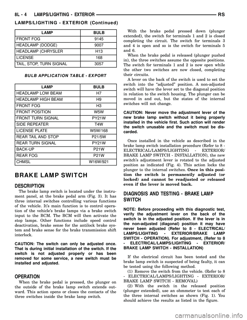
three switches inside the brake lamp switch.With the brake pedal pressed down (plunger
extended), the switch for terminals 1 and 2 is closed
completing the circuit. The switch for terminals 3
and 4 is open and so is the switch for terminals 5
and 6.
When the brake pedal is released (plunger pushed
in), the three switches assume the opposite positions.
The switch for terminals 1 and 2 is now open while
the other two switches are now closed, completing
their circuits.
A lever on the back of the switch is used to set the
switch into the ªadjustedº position. A non-adjusted
switch will have the lever set to the diagonal position
in relation to the switch housing. The plunger can be
moved in and out, but the states of the internal
switches will not change.
CAUTION: Never move the adjustment lever of the
new brake lamp switch without it being properly
installed in the vehicle first. Such action will render
the switch unusable and the switch must be dis-
carded.
Once installed in the vehicle as described in the
brake lamp switch installation procedure (Refer to 8 -
ELECTRICAL/LAMPS/LIGHTING - EXTERIOR/
BRAKE LAMP SWITCH - INSTALLATION), the new
switch's adjustment lever is rotated to the adjusted
position as indicated (Fig. 4). This action locks the
plunger to the internal switches.Once in this posi-
tion the switch is permanently adjusted (or
locked) and cannot be readjusted or released
even if the lever is moved back.
DIAGNOSIS AND TESTING - BRAKE LAMP
SWITCH
NOTE: Before proceeding with this diagnostic test,
verify the adjustment lever on the back of the
switch is in the adjusted position. If the lever is in
the non-adjusted (diagonal) position it may have
never been adjusted (Refer to 8 - ELECTRICAL/
LAMPS/LIGHTING - EXTERIOR/BRAKE LAMP
SWITCH - OPERATION). For adjustment, (Refer to 8
- ELECTRICAL/LAMPS/LIGHTING - EXTERIOR/
BRAKE LAMP SWITCH - INSTALLATION)
If the electrical circuit has been tested and the
brake lamp switch is suspected of being faulty, it can
be tested using the following method.
(1) Remove the switch from the vehicle. (Refer to 8
- ELECTRICAL/LAMPS/LIGHTING - EXTERIOR/
BRAKE LAMP SWITCH - REMOVAL)
(2) With the switch in the released position
(plunger extended), use an ohmmeter to test each of
the three internal switches as shown (Fig. 1). You
should achieve the results as listed in the figure.
8L - 4 LAMPS/LIGHTING - EXTERIORRS
LAMPS/LIGHTING - EXTERIOR (Continued)
Page 391 of 2339
(b) Install the switch in its bracket by aligning
the index tab on the switch with the slot in the
mounting bracket.
(c) When the switch is fully seated in its
bracket, rotate the switch clockwise approximately
30É to lock the switch into place.
(d) With the brake pedal in the fully released
position, move the lever on the back of the brake
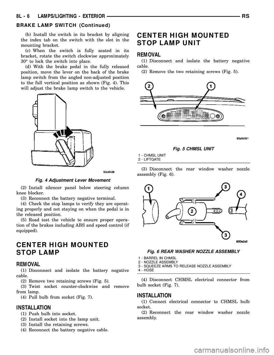
lamp switch from the angled non-adjusted position
to the full vertical position as shown (Fig. 4). This
will adjust the brake lamp switch to the vehicle.
(2) Install silencer panel below steering column
knee blocker.
(3) Reconnect the battery negative terminal.
(4) Check the stop lamps to verify they are operat-
ing properly and not staying on when the pedal is in
the released position.
(5) Road test the vehicle to ensure proper opera-
tion of the brakes including ABS and speed control (if
equipped).
CENTER HIGH MOUNTED
STOP LAMP
REMOVAL
(1) Disconnect and isolate the battery negative
cable.
(2) Remove two retaining screws (Fig. 5).
(3) Twist socket counter-clockwise and remove
from lamp.
(4) Pull bulb from socket (Fig. 7).
INSTALLATION
(1) Push bulb into socket.
(2) Install socket into the lamp unit.
(3) Install the retaining screws.
(4) Reconnect the battery negative cable.
CENTER HIGH MOUNTED
STOP LAMP UNIT
REMOVAL
(1) Disconnect and isolate the battery negative
cable.
(2) Remove the two retaining screws (Fig. 5).
(3) Disconnect the rear window washer nozzle
assembly (Fig. 6).
(4) Disconnect CHMSL electrical connector from
bulb socket (Fig. 7).
INSTALLATION
(1) Connect electrical connector to CHMSL bulb
socket.
(2) Reconnect the rear window washer nozzle
assembly.
Fig. 4 Adjustment Lever Movement
Fig. 5 CHMSL UNIT
1 - CHMSL UNIT
2 - LIFTGATE
Fig. 6 REAR WASHER NOZZLE ASSEMBLY
1 - BARREL IN CHMSL
2 - NOZZLE ASSEMBLY
3 - SQUEEZE ARMS TO RELEASE NOZZLE ASSEMBLY
4 - HOSE
8L - 6 LAMPS/LIGHTING - EXTERIORRS
BRAKE LAMP SWITCH (Continued)
Page 398 of 2339

(4) Remove wiring connector from bulb by sliding
red latch lock rearward and then depressing release
tab.
(5) Rotate headlamp bulb retaining ring counter-
clockwise.
INSTALLATION
DODGE
(1) Install headlamp bulb to the headlamp unit.
(2) Install headlamp bulb retaining ring.
(3) Connect wiring connector to bulb.
(4) Install the headlamp unit.
(5) Install headlamp unit retaining screws.
(6) Connect the battery negative cable.
CHRYSLER
(1) Install headlamp bulb to the headlamp unit.
(2) Rotate bulb clockwise to lock bulb in headlamp
unit.
(3) Connect wiring connector to bulb and slide red
latch lock forward.
(4) Install the headlamp unit.
(5) Install headlamp unit retaining screws.
(6) Connect the battery negative cable.
HEADLAMP SWITCH
DIAGNOSIS AND TESTING - HEADLAMP
SWITCH
Using a Digital Multi-meter, perform the HEAD-
LAMP SWITCH CONTINUITY test and refer to (Fig.
11).
If the Headlamp Switch is not within specifications
replace the switch.
HEADLAMP SWITCH CONTINUITY
HEADLAMP
SWITCH
POSITION13-WAY
CONNECTOR
TERMINALRESISTANCE
OFF 11 TO 6 3651 - 3729V
PARKING
LAMPS ON11 TO 6 1697 - 2517V
PARKING
LAMPS WITH
FRONT FOG
LAMPS ON11 TO 6 5765 - 5886V
HEADLAMPS
ON11 TO 6 788 - 809V
AUTO ON 11 TO 6 10056 - 10264V
HEADLAMPS
ON WITH
FRONT FOG
LAMPS11 TO 6 1171 - 1200V
AUTO ON WITH
FRONT FOG
LAMPS ON11 TO 6 24278 - 24773V
DIMMER
POSITION13-WAY
CONNECTOR
TERMINALRESISTANCE
DOME 12 TO 6 15568 - 23357V
PARADE 12 TO 6 5168 - 7757V
DIM HIGH 12 TO 6 2288 - 3437V
DIM LOW 12 TO 6 688 - 1037V
OFF 12 TO 6 240 - 365V
REMOVAL
(1) Disconnect and isolate the battery negative
cable.
(2) Remove the Instrument Panel Lower Steering
Column Cover. Refer to Body, Instrument Panel,
Lower Steering Column Cover, Removal.
(3) Reach up behind the left side of the instrument
panel and depress spring clip on top or bottom of
headlamp switch. Firmly push out on the headlamp
switch assembly.
(4) Disconnect the wiring connectors.
(5) Remove switch from vehicle.
INSTALLATION
(1) Connect the wiring connectors.
(2) Place headlamp switch assembly into position
and firmly snap into place.
(3) Install the Instrument Panel Lower Steering
Column Cover. Refer to Body, Instrument Panel,
Lower Steering Column Cover, Installation.
(4) Connect the battery negative cable.
Fig. 11 HEADLAMP SWITCH CONNECTOR
RSLAMPS/LIGHTING - EXTERIOR8L-13
HEADLAMP (Continued)
Page 402 of 2339
REMOVAL
(1) Disconnect and isolate the battery negative
cable.
(2) Remove the three retaining screws.
(3) Disconnect the central wiring harness connec-
tor from the headlamp unit.
(4) Remove the headlamp unit from the vehicle by
rotating the turn signal area out and towards the
center of the vehicle.
INSTALLATION
(1) Connect the wiring harness to the headlamp
unit's central connector.
(2) Place the headlamp unit in the headlamp unit
pocket in front end first by placing the inboard side
behind the fascia. Complete the installation by rotat-
ing the turn signal area of the headlamp into place.
(3) Place headlamp unit into headlamp unit pocket
in front end.
(4) Install the three retaining screws.
(5) Connect the battery negative cable.
(6) Verify vehicle and system operation.
LICENSE LAMP
REMOVAL
(1) Disconnect and isolate the battery negative
cable.
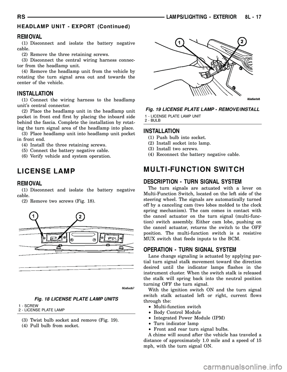
(2) Remove two screws (Fig. 18).
(3) Twist bulb socket and remove (Fig. 19).
(4) Pull bulb from socket.
INSTALLATION
(1) Push bulb into socket.
(2) Install socket into lamp.
(3) Install two screws.
(4) Reconnect the battery negative cable.
MULTI-FUNCTION SWITCH
DESCRIPTION - TURN SIGNAL SYSTEM
The turn signals are actuated with a lever on
Multi-Function Switch, located on the left side of the
steering wheel. The signals are automatically turned
off by a canceling cam (two lobes molded to the clock
spring mechanism). The cam comes in contact with
the cancel actuator on the turn signal (multi-func-
tion) switch assembly. Either cam lobe, pushing on
the cancel actuator, returns the switch to the OFF
position. The multi-function switch is a resistive
MUX switch that feeds inputs to the BCM.
OPERATION - TURN SIGNAL SYSTEM
Lane change signaling is actuated by applying par-
tial turn signal stalk movement toward the direction
desired until the indicator lamps flashes in the
instrument cluster. When the switch stalk is released
the stalk will spring back into the neutral position
turning OFF the turn signal.
With the ignition switch ON and the turn signal
switch stalk actuated left or right, current flows
through the:
²Multi-function switch
²Body Control Module
²Integrated Power Module (IPM)
²Turn indicator lamp
²Front and rear turn signal bulbs.
A chime will sound after the vehicle has traveled a
distance of approximately 1.0 mile and a speed of 15
mph, with the turn signal ON.
Fig. 18 LICENSE PLATE LAMP UNITS
1 - SCREW
2 - LICENSE PLATE LAMP
Fig. 19 LICENSE PLATE LAMP - REMOVE/INSTALL
1 - LICENSE PLATE LAMP UNIT
2 - BULB
RSLAMPS/LIGHTING - EXTERIOR8L-17
HEADLAMP UNIT - EXPORT (Continued)
Page 407 of 2339
DOME/CARGO LAMP
REMOVAL
(1) Disconnect and isolate the battery negative
cable.
(2) Using a flat bladed tool, pry off the lamp lens.
(3) Remove bulb from lamp.
INSTALLATION
(1) Install bulb to lamp.
(2) Press lens into place.
(3) Connect battery negative cable.
GLOVE BOX LAMP SWITCH
REMOVAL
(1) Disconnect and isolate the battery negative
cable.
(2) Open glove box door.
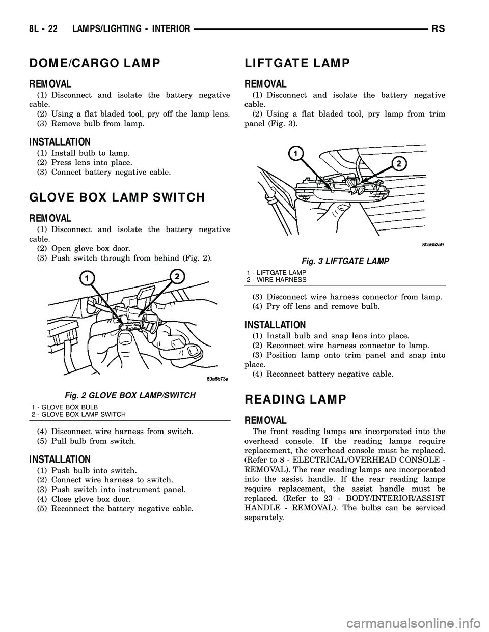
(3) Push switch through from behind (Fig. 2).
(4) Disconnect wire harness from switch.
(5) Pull bulb from switch.
INSTALLATION
(1) Push bulb into switch.
(2) Connect wire harness to switch.
(3) Push switch into instrument panel.
(4) Close glove box door.
(5) Reconnect the battery negative cable.
LIFTGATE LAMP
REMOVAL
(1) Disconnect and isolate the battery negative
cable.
(2) Using a flat bladed tool, pry lamp from trim
panel (Fig. 3).
(3) Disconnect wire harness connector from lamp.
(4) Pry off lens and remove bulb.
INSTALLATION
(1) Install bulb and snap lens into place.
(2) Reconnect wire harness connector to lamp.
(3) Position lamp onto trim panel and snap into
place.
(4) Reconnect battery negative cable.
READING LAMP
REMOVAL
The front reading lamps are incorporated into the
overhead console. If the reading lamps require
replacement, the overhead console must be replaced.
(Refer to 8 - ELECTRICAL/OVERHEAD CONSOLE -
REMOVAL). The rear reading lamps are incorporated
into the assist handle. If the rear reading lamps
require replacement, the assist handle must be
replaced. (Refer to 23 - BODY/INTERIOR/ASSIST
HANDLE - REMOVAL). The bulbs can be serviced
separately.
Fig. 2 GLOVE BOX LAMP/SWITCH
1 - GLOVE BOX BULB
2 - GLOVE BOX LAMP SWITCH
Fig. 3 LIFTGATE LAMP
1 - LIFTGATE LAMP
2 - WIRE HARNESS
8L - 22 LAMPS/LIGHTING - INTERIORRS
Page 415 of 2339

(1) Using the Variance Settings map, find your
geographic location and note the zone number (Fig.
3).
(2) Turn the ignition switch to the On position. If
the compass/thermometer data is not currently being
displayed, momentarily depress and release the C/T
push button to reach the compass/thermometer dis-
play.
(3) On Electronic Vehicle Information Center
(EVIC) and Compass Mini-Trip Computer (CMTC)
equipped vehicles depress the Reset push button and
hold the button down until ªVAR = XXº appears in
the display. This takes about five seconds. On Com-
pass Temperature Module (CT) equipped vehicles
depress the C/T push button and US/M push button
down until ªVAR = XXº appears in the display. This
takes about five seconds.
(4) Release the push button(s). ªVAR =XX º will
remain in the display. ªXXº equals the current vari-
ance zone setting.
(5) On Electronic Vehicle Information Center
(EVIC) and Compass Mini-Trip Computer (CMTC)
equipped vehicles momentarily depress and release
theSTEPbutton to step through the zone numbers,
until the zone number for your geographic location
appears in the display. On Compass Temperature
Module (CT) equipped vehicles depress theUS/M
push button to step through the zone numbers, until
the zone number for your geographic location
appears in the display.(6) On Electronic Vehicle Information Center
(EVIC) and Compass Mini-Trip Computer (CMTC)
equipped vehicles momentarily depress and release
theRESETpush button to enter the displayed zone
number into the EVIC/CMTC module memory. On
Compass Temperature Module (CT) equipped vehicles
depress theC/Tpush button to enter the displayed
zone number into the electronic module memory.
(7) Confirm that the correct directions are now
indicated by the compass.
REMOVAL
(1) Disconnect and isolate the battery negative
cable.
(2) Remove the overhead console retaining screw,
located in the front of console.
(3) Grasp the sides of the overhead console and
pull straight down evenly to disengage the two snap
clips at the rear of the unit.
(4) Lower the overhead console far enough to
access the wire harness connectors.
(5) Disconnect the EVIC, CMTC or CT electronic
module and the reading/courtesy lamps electrical
connector.
(6) Remove the overhead console from the vehicle.
INSTALLATION
(1) Position the overhead console in the vehicle.
Fig. 3 Variance Settings
8M - 6 OVERHEAD CONSOLERS
OVERHEAD CONSOLE (Continued)
Page 416 of 2339
(2) Connect the EVIC, CMTC or CT electronic
module and the reading/courtesy lamps electrical
connector.
(3) Using your fingertips, grasp the sides of the
overhead console and push straight up evenly to
engage the two snap clips at the rear of the unit.
CAUTION: DO NOT PRESS ON THE SUNGLASS
STORAGE BIN DOOR. DAMAGE TO THE DOOR MAY
RESULT.
(4) Install the overhead console retaining screw,
located in the front of console. Torque the screw to
1.2 N´m (10 in. lbs.).
(5) Connect the remote negative battery cable.
SPECIAL TOOLS
OVERHEAD CONSOLE
ELECTRONIC VEHICLE INFO
CENTER
DESCRIPTION
The Electronic Vehicle Information Center (EVIC)
is located in the overhead console. The EVIC features
a large Vacuum Fluorescent Display (VFD) screen for
displaying information, and back-lit push button
switches labeled C/T (compass/thermometer), RESET,
STEP, and MENU. The EVIC module contains a cen-
tral processing unit and interfaces with other elec-
tronic modules in the vehicle over the Programmable
Communications Interface (PCI) data bus circuit.
The EVIC ªMenuº push button provides the vehicle
operator with a user interface, which allows the
selection of several optional customer programmable
electronic features to suit individual preferences.
(Refer to 8 - ELECTRICAL/OVERHEAD CONSOLE/
ELECTRONIC VEHICLE INFO CENTER - STAN-
DARD PROCEDURE - ELECTRONIC VEHICLE
INFORMATION CENTER PROGRAMMING).
If the vehicle is equipped with the optional univer-
sal transmitter transceiver, the EVIC will also dis-
play messages and an icon indicating when the
universal transmitter transceiver is being trained,
which of the three transmitter buttons is transmit-
ting, and when the transceiver is cleared.Data input for all EVIC functions, including VFD
dimming level, is received through the PCI data bus
circuit. The EVIC module uses its internal program-
ming and all of its data inputs to calculate and dis-
play the requested data. If the data displayed is
incorrect, perform the SELF - DIAGNOSTIC TEST
(Refer to 8 - ELECTRICAL/OVERHEAD CONSOLE -
DIAGNOSIS AND TESTING). If these tests prove
inconclusive, the use of a DRBIIItscan tool and the
proper diagnostic procedures information are recom-
mended for further testing of the EVIC module and
the PCI data bus circuit.
The EVIC module cannot be repaired, and is avail-
able for service only as a unit. This unit includes the
plastic module and display lens. If any of these com-
ponents is faulty or damaged, the complete EVIC
module must be replaced.
OPERATION
The Electronic Vehicle Information Center (EVIC)
uses both non-switched and ignition switched sources
of battery current so that some of its features remain
operational at any time, while others may only oper-
ate with the ignition switch in the On position. When
the ignition switch is turned to the On position, the
EVIC module Vacuum Fluorescent Display (VFD)
will return to the last function being displayed before
the ignition was turned to the Off position.
The compass/thermometer display is the normal
EVIC display. With the ignition switch in the On
position, momentarily depressing and releasing the
C/T (compass/thermometer) push button switch will
cause the EVIC to return to the compass/thermome-
ter/trip computer display mode from any other mode.
While in the compass/thermometer/trip computer dis-
play mode, momentarily depressing and releasing the
Step push button will step through the available trip
computer display options.
The EVIC trip computer features several functions
that can be reset. The functions that can be reset
are:
²Average fuel economy
²Trip odometer
²Elapsed time
With the ignition switch in the On position and
with one of the functions of the trip computer that
can be reset currently displayed, depressing the
Reset push button twice within four seconds will per-
form a global reset, and all of the trip computer
information that can be reset will be reset to zero.
With the ignition switch in the On position and the
function that is to be reset currently displayed,
momentarily depressing and holding the Reset push
button for one second will perform a local reset, and
only the value of the displayed function will be reset
to zero. A global or local reset will only occur if the
DEGAUSSING TOOL #6029
RSOVERHEAD CONSOLE8M-7
OVERHEAD CONSOLE (Continued)