rear lamp CHRYSLER VOYAGER 2005 Workshop Manual
[x] Cancel search | Manufacturer: CHRYSLER, Model Year: 2005, Model line: VOYAGER, Model: CHRYSLER VOYAGER 2005Pages: 2339, PDF Size: 59.69 MB
Page 431 of 2339

STANDARD PROCEDURE
LIFTGATE ADJUSTMENT
In order for the power liftgate system to function
properly the liftgate must move freely and smoothly.
The power liftgate system can accommodate for some
minor changes in the effort required to move the lift-
gate. However, in extreme conditions the liftgate may
need to be mechanically adjusted for proper fit and
finish. (Refer to 23 - BODY/DECKLID/HATCH/LIFT-
GATE/TAILGATE/LIFTGATE - INSTALLATION) for
detailed instructions.
If a problem exists with the power liftgate and it is
suspected to be extreme effort, check the liftgate prop
rods and hinges for free movement.
NOTE: Routine application of Mopar MP-50Tor
equivalent on the chrome prop rod shafts and lift-
gate latch and hinges will help keep the liftgate in
good working order.
POWER LIFTGATE LEARN CYCLE
Any time a power liftgate component is removed,
replaced or a liftgate adjustment is performed a learn
cycle must be performed. This learn cycle enables the
power liftgate control module to learn or relearn
information (travel limits, resistance to door travel,
etc.) which allows it to perform properly and safely.
Perform the following to complete a power liftgate
learn cycle:
(1) Obtain a DRBIIIt, or equivalent scan tool.
(2) Connect the scan tool to the vehicle and check
for any power liftgate system stored Diagnostic Trou-
ble Codes (DTCs), correct and erase any stored
DTCs.
(3) Using the scan tool, Go into Test Routine Menu
and select the power open command.
(4) Select the power close command.
(5) The liftgate learn cycle is complete.
If a DRBIIItor equivalent scan tool is not avail-
able, the learn cycle can be performed by actuating
the liftgate using any of the normal command
switches. Be certain to cycle the liftgate through a
complete open and close cycle before returning the
vehicle to service.
NOTE: If the power liftgate will not complete a full
cycle a problem exists with the power liftgate sys-
tem. (Refer to 8 - ELECTRICAL/POWER DOORS -
DIAGNOSIS AND TESTING).
CHIME/THERMISTOR
DESCRIPTION
The chime/thermistor assembly is a small capacitor
shaped electrical component mounted to the rear
license plate lamp housing assembly (Fig. 2) , located
just above the license plate. The chime portion of the
assembly controls the audible chime sound heard at
the rear of the vehicle when the power liftgate is in
motion. The thermistor portion of the assembly is a
temperature sensor, used by the power liftgate con-
trol module. The chime/thermistor assembly is a ser-
viceable component.
OPERATION
The chime/thermistor assembly performs two dif-
ferent functions for the power liftgate system. First,
the chime portion provides an audible chime sound
which is controlled by the power liftgate control mod-
ule. The chime/thermistor assembly is hardwired to
the power liftgate control module. Second the ther-
mistor provides a outside temperature reading by
way of a resistance reading supplied to the power
liftgate control module. As temperature increases the
resistance reading increases, as temperature
decreases the resistance reading decreases.
REMOVAL
(1) Disconnect and isolate the battery negative
cable.
Fig. 2 REAR LIGHT BAR
1 - CHIME / THERMISTOR
2 - ELECTRIC RELEASE HANDLE SWITCH
3 - LICENSE PLATE LAMPS
8N - 8 POWER LIFTGATE SYSTEMRS
POWER LIFTGATE SYSTEM (Continued)
Page 433 of 2339
INSTALLATION
(1) Position the engage actuator in the vehicle and
connect the engage actuator electrical connector.
(2) Install the two engage actuator retaining
screws.
(3) Manually disengage the actuator.
(4) Install the left rear D-pillar trim on the vehi-
cle, (Refer to 23 - BODY/INTERIOR/LEFT D-PILLAR
TRIM PANEL - INSTALLATION).
(5) Connect the battery negative cable.
(6) Using an appropriate scan tool, check and
erase any power liftgate control module diagnostic
trouble codes.
(7) Verify power liftgate system and engage actua-
tor operation. Cycle the power liftgate through one
complete open and close cycle.
EXTERIOR HANDLE SWITCH
DESCRIPTION
The exterior handle switch is an electronic release
switch mounted to the rear license plate lamp hous-
ing assembly, located just above the license plate.
This switch controls the power liftgate release func-
tion and is also capable of reversing the power lift-
gate when it is in motion. A full power open cycle
cannot be performed using this switch, only one of
the power open command switches (key fob and over-
head console mounted) can be used to perform a full
power open cycle. The exterior handle switch is a ser-
viceable component.
OPERATION
When the exterior handle switch is depressed, with
the liftgate in the closed position, a message is sent
to the Body Control Module (BCM). The BCM then
sends a signal to the power liftgate control module
via the Programmable Communication Interface
(PCI) data bus circuit. The power liftgate control
module then sends a signal to the power latch
mounted actuator, which moves the liftgate from the
primary closed and latched position to the open and
movable position. If the liftgate is not pulled open
once the latch releases within a few seconds, the
latch will cinch closed again.
REMOVAL
(1) Disconnect and isolate the battery negative
cable.
(2) Open the liftgate and remove the liftgate trim
panel, (Refer to 23 - BODY/DECKLID/HATCH/LIFT-
GATE/TAILGATE/TRIM PANEL - REMOVAL).
(3) Remove the rear lamp bar assembly from the
vehicle.(4) Locate the two wires going to the exterior han-
dle switch. Cut the tie strap and trace the wires to
the large electrical connector and back the wires out
of the large connector and through the grommet.
Take care to mark the location of the wire ter-
minals in relation to the large connector so
that they are positioned in the appropriate cav-
ities upon switch installation.
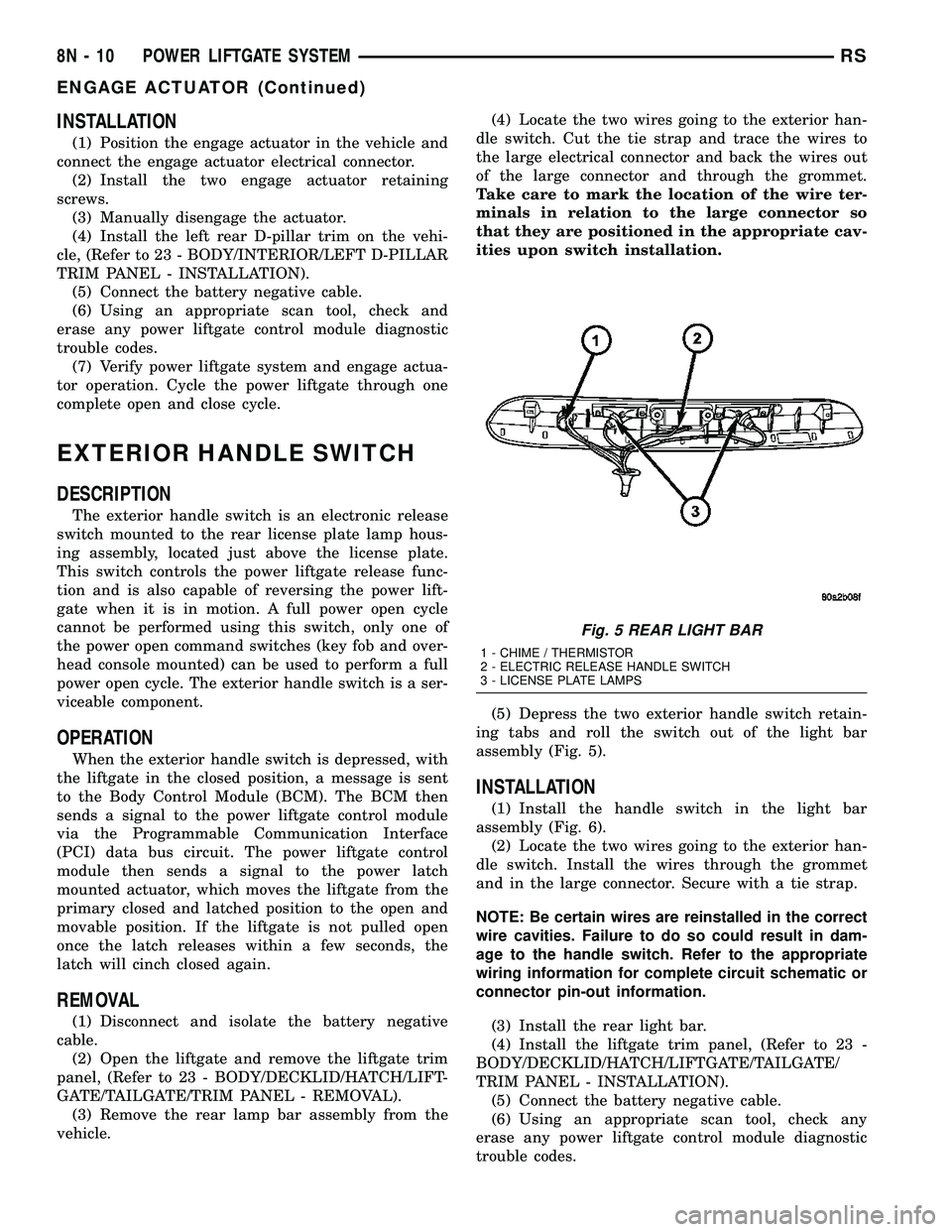
(5) Depress the two exterior handle switch retain-
ing tabs and roll the switch out of the light bar
assembly (Fig. 5).
INSTALLATION
(1) Install the handle switch in the light bar
assembly (Fig. 6).
(2) Locate the two wires going to the exterior han-
dle switch. Install the wires through the grommet
and in the large connector. Secure with a tie strap.
NOTE: Be certain wires are reinstalled in the correct
wire cavities. Failure to do so could result in dam-
age to the handle switch. Refer to the appropriate
wiring information for complete circuit schematic or
connector pin-out information.
(3) Install the rear light bar.
(4) Install the liftgate trim panel, (Refer to 23 -
BODY/DECKLID/HATCH/LIFTGATE/TAILGATE/
TRIM PANEL - INSTALLATION).
(5) Connect the battery negative cable.
(6) Using an appropriate scan tool, check any
erase any power liftgate control module diagnostic
trouble codes.
Fig. 5 REAR LIGHT BAR
1 - CHIME / THERMISTOR
2 - ELECTRIC RELEASE HANDLE SWITCH
3 - LICENSE PLATE LAMPS
8N - 10 POWER LIFTGATE SYSTEMRS
ENGAGE ACTUATOR (Continued)
Page 434 of 2339

(7) Verify power liftgate system and handle switch
operation. Cycle the power liftgate through one com-
plete open and close cycle, this will allow the power
liftgate control module to relearn its cycle with the
new components.
FULL OPEN SWITCH
DESCRIPTION
The full open switch is located on the gear motor
housing (Fig. 7) and is used to signal the power lift-
gate control module when the power liftgate is in the
full open position. Two wires are used from the full
open switch contacts to the gear motor assemblies
main electrical connector. The full open switch is a
serviceable component.
OPERATION
When the power liftgate reaches the full open posi-
tion, the gear motor housing mounted full open
switch electrical contacts close. This sends a ground
signal to the power liftgate control module, telling
the module that the liftgate has reached the full open
position.
REMOVAL
(1) Disconnect and isolate the battery negative
cable.
(2) Remove the lift gear and link rod assembly
from the vehicle(Refer to 8 - ELECTRICAL/POWER
DOORS/CONTROL ROD - REMOVAL).(3) Cut the two wires leading to the full open
switch or back the wires out of the electrical connec-
tor.
(4) Remove the full open switch retaining screw
and remove the full open switch from the gear motor
housing assembly.
INSTALLATION
(1) Perform a wiring repair on the full open switch
wires following the approved procedure in the Wiring
section of the service manual. Or install new termi-
nals on the wire ends and reinstall in the main lift-
gate motor electrical connector.
(2) Position and install the full open switch retain-
ing screw.
(3) Install the power liftgate lift gear and link rod
assembly. (Refer to 8 - ELECTRICAL/POWER
DOORS/CONTROL ROD - INSTALLATION)
(4) Connect the battery negative cable.
(5) Using an appropriate scan tool, check any
erase any power liftgate control module diagnostic
trouble codes.
(6) Verify power liftgate system and full open
switch operation. Cycle the power liftgate through
one complete open and close cycle, this will allow the
power liftgate control module to relearn its cycle with
the new components.
Fig. 6 REAR LIGHT BAR
1 - CHIME / THERMISTOR
2 - ELECTRIC RELEASE HANDLE SWITCH
3 - LICENSE PLATE LAMPS
Fig. 7 FULL OPEN SWITCH LOCATION
1 - FULL OPEN SWITCH
2 - GEAR MOTOR ASSEMBLY RETAINING BOLT (1 OF 3)
RSPOWER LIFTGATE SYSTEM8N-11
EXTERIOR HANDLE SWITCH (Continued)
Page 449 of 2339
POWER MIRRORS
TABLE OF CONTENTS
page page
POWER MIRRORS
DESCRIPTION.........................26
OPERATION...........................26
DIAGNOSIS AND TESTING
POWER MIRRORS....................27
AUTOMATIC DAY / NIGHT MIRROR
DESCRIPTION.........................28
OPERATION...........................28
DIAGNOSIS AND TESTING
AUTOMATIC DAY / NIGHT MIRROR.......28
POWER FOLDAWAY MIRROR SWITCH -
EXPORT
DESCRIPTION.........................29OPERATION...........................29
REMOVAL.............................29
INSTALLATION.........................30
REMOTE SWITCH
DIAGNOSIS AND TESTING
REMOTE SWITCH.....................30
REMOVAL.............................30
INSTALLATION.........................30
SIDEVIEW MIRROR
REMOVAL.............................30
POWER MIRRORS
DESCRIPTION
If equipped with power mirrors, the control switch
is located on the instrument panel to the left of the
headlamp switch.
OPERATION
The power mirrors are connected to battery feed at
all times. Each mirror head contains two electric
motors, two drive mechanisms, an electric heating
element, and the mirror glass. If the vehicle is
equipped with the optional memory system, the
driver side mirror head also contains both a horizon-
tal and a vertical motor position sensor. One motor
and drive controls mirror up-and-down movement,
and the other controls right-and-left movement.An optional driver side outside electrochromic mir-
ror is able to automatically change its reflectance
level. This mirror is controlled by the circuitry of the
automatic day/night inside rear view mirror. A thin
layer of electrochromic material between two pieces
of conductive glass make up the face of the mirror.
Two photocell sensors on the inside rear view mirror
are used to monitor light levels and adjust the reflec-
tance of both the inside and driver side outside mir-
rors. This change in reflectance helps to reduce the
glare of headlamps approaching the vehicle from the
rear. (Refer to 8 - ELECTRICAL/POWER MIRRORS/
AUTOMATIC DAY / NIGHT MIRROR - DESCRIP-
TION) for more information on this system.
The motors which operate the mirrors are part of
the mirror assembly and cannot be serviced sepa-
rately.
8N - 26 POWER MIRRORSRS
Page 451 of 2339
AUTOMATIC DAY / NIGHT
MIRROR
DESCRIPTION
An automatic dimming inside day/night rear view
mirror and an automatic dimming driver side outside
rear view mirror are available factory-installed
options on this model. Following is a general descrip-
tion of this optional equipment.
The automatic day/night mirror is able to automat-
ically change its reflectance. A thin layer of electro-
chromic material between two pieces of conductive
glass make up the face of the mirror. Two photocell
sensors are used to monitor light levels and adjust
the reflectance of the mirror to reduce the glare of
headlamps approaching the vehicle from the rear.
For removal procedures, (Refer to 23 - BODY/IN-
TERIOR/REAR VIEW MIRROR - REMOVAL).
OPERATION
The ambient photocell sensor faces forward, to
detect the outside light levels. A second sensor faces
rearward to detect the light level received through
the vehicles back window. When the difference
between the two light levels becomes too great (the
light level received at the rear of the mirror is much
higher than that at the front of the mirror), the mir-
ror begins to darken.
The mirror switch allows the driver a manual con-
trol of whether the automatic dimming feature is
operational. When AUTO is selected a small Light-
Emitting Diode (LED), to the right of the mirror
switch, is illuminated. The automatic dimming fea-
ture will only operate when the ignition switch is in
the On position. The mirror also senses the backup
lamp circuit, and will automatically disable its self-
dimming feature whenever the transmission gear
selector is in the Reverse position.
NOTE: The mirror always defaults to an ON state
upon ignition.
The driver side automatic dimming mirror is stan-
dard with the automatic dimming inside mirror. The
signal to control the dimming of that mirror is gen-
erated by the automatic day/night inside rear view
mirror circuitry. That signal is then delivered to the
driver side outside rear view mirror on a hard wired
circuit.
The automatic day/night mirror cannot be
repaired. If faulty or damaged, the entire inside rear
view mirror assembly must be replaced.
DIAGNOSIS AND TESTING
AUTOMATIC DAY / NIGHT MIRROR
For circuit descriptions and diagrams, refer to the
appropriate wiring information. The wiring informa-
tion includes wiring diagrams, proper wire and con-
nector repair procedures, details of wire harness
routing and retention, connector pin-out information
and location views for the various wire harness con-
nectors, splices and grounds.
(1) Check the fuse in the intelligent power module.
If OK, go to Step 2. If not OK, repair the shorted cir-
cuit or component as required and replace the faulty
fuse.
(2) Turn the ignition switch to the On position.
Check for battery voltage at the fuse in the intelli-
gent power module. If OK, go to Step 3. If not OK,
repair the open circuit to the ignition switch as
required.
(3) Unplug the wire harness connector from the
automatic day/night mirror. Check for battery voltage
at the fused ignition switch output circuit cavity of
the automatic day/night mirror wire harness connec-
tor. If OK, go to Step 4. If not OK, repair the open
circuit to the junction block as required.
(4) Turn the ignition switch to the Off position.
Check for continuity between the ground circuit cav-
ity of the automatic day/night mirror wire harness
connector and a good ground. There should be conti-
nuity. If OK, go to Step 5. If not OK, repair the cir-
cuit to ground as required.
(5) Turn the ignition switch to the On position. Set
the parking brake. Place the transmission gear selec-
tor lever in the Reverse position. Check for battery
voltage at the backup lamp switch output circuit cav-
ity of the automatic day/night mirror wire harness
connector. If voltage is present, reinstall the auto-
matic day/night mirror wire harness connector and
go to Step 6. If not OK, repair the open circuit as
required.
(6) Place the transmission gear selector lever in
the Neutral position. Place the automatic day/night
mirror switch in the On (LED in the switch is
lighted) position. Cover the forward facing ambient
photocell sensor to keep out any ambient light.
NOTE: The ambient photocell sensor must be cov-
ered completely, so that no light reaches the sen-
sor. Use a finger pressed tightly against the sensor,
or cover the sensor completely with electrical tape.
(7) Shine a light into the rearward facing head-
lamp photocell sensor. The automatic day/night mir-
ror should darken. The automatic day/night mirror
should darken within 2 minutes if testing for the
first time. For immediate response, turn the vehicle
8N - 28 POWER MIRRORSRS
Page 518 of 2339

WARNING: Wait two minutes for the airbag system
reserve capacitor to discharge before beginning
any airbag system or component service. Failure to
do so may result in accidental airbag deployment,
personal injury or death.
(4) Clean powder residue from interior of vehicle
(Refer to 8 - ELECTRICAL/RESTRAINTS - STAN-
DARD PROCEDURE - SERVICE AFTER AN AIR-
BAG DEPLOYMENT).
(5) Remove instrument panel (Refer to 23 - BODY/
INSTRUMENT PANEL/INSTRUMENT PANEL
ASSEMBLY - REMOVAL).
(6) Remove all reusable components from the
upper instrument panel and transfer to the new
instrument panel.
UNDEPLOYED AIRBAG
(1) Open hood.
(2) Disconnect and isolate the battery negative
cable.
(3)
WARNING: Wait two minutes for the airbag system
reserve capacitor to discharge before beginning
any airbag system or component service. Failure to
do so may result in accidental airbag deployment,
personal injury or death.
(4) Remove center console bin between front seats.
(5) Remove left front door sill plate using a trim
stick (special tool #C-4755) or equivalent, and gently
prying up on sill plate.
(6) Remove left cowl panel using a trim stick or
equivalent, and gently prying out on cowl panel.
(7) Remove four screws to lower steering column
cover and remove cover.
(8) Unsnap parking brake lever from knee blocker
reinforcement.
(9) Remove Data Link Connector (DLC) from knee
blocker.
(10) Remove screws to knee blocker.
(11) Unsnap left A-pillar lower extension trim
using a trim stick or equivalent.
(12) Remove three left side instrument panel A-pil-
lar retaining bolts and loosen the instrument panel
roll down bolt.
(13) Remove four nuts at brake pedal support
bracket to instrument panel.
(14) Using a trim stick or equivalent, gently pry
off left side upper A-pillar trim.
(15) Remove six screws and two wiring connectors
to lower instrument panel cubby bin at bottom of
center stack.
(16) Remove two left side nuts at instrument panel
center stack support to floor.(17) Remove two right side nuts at instrument
panel center stack support to floor.
(18) Remove right front door sill plate using a trim
stick or equivalent, and gently prying up on sill
plate.
(19) Remove right cowl panel using a trim stick or
equivalent, and gently prying out on cowl panel.
(20) Using a trim stick or equivalent, gently pry
out on right instrument panel end cap.
(21) Unsnap right A-pillar lower extension trim
using a trim stick or equivalent.
(22) Remove three right side instrument panel
A-pillar retaining bolts and loosen the instrument
panel roll down bolt.
(23) Using a trim stick or equivalent, gently pry
off right side upper A-pillar trim.
(24) Open glove box, pinch in sides and roll down
towards floor. With a firm pull, snap glove box door
off hinges and remove.
(25) Using a trim stick or equivalent, gently pry
up on rear of instrument panel top cover and then
pull rearward and out.
(26) Using a trim stick or equivalent, gently pry
off the filler bezel just above the cup holder to expose
the lower screws to center bezel.
(27) Remove two screws and then using a trim
stick or equivalent, gently pry off instrument panel
center bezel.
(28) Remove center bezel wiring connectors to
HVAC control and switch assembly (hazard, rear
wiper/washer, heated seats) and remove bezel.
(29) Slide cup holder assembly from instrument
panel.
(30) Remove nineteen screws to right lower instru-
ment panel trim (glove box surround), unplug glove
box lamp wire connector, and remove panel.
(31) Remove four screws and wiring connectors to
radio and remove radio.
(32) Remove one far left instrument panel speaker
retaining screw.
(33) Remove four screws along top front edge of
instrument panel cover/pad.
(34) Remove seven lower instrument panel cover/
pad retaining screws starting from right of vehicle
and only removing these seven, not all of them.
(35) Remove six upper fence line instrument panel
retaining bolts.
(36) Roll back instrument panel just enough to
increase access to the passenger airbag retaining
bolts at the reinforcement. Lift the instrument panel
up slightly so as not to damage the air distribution to
HVAC unit seal.
(37) Disconnect the passenger airbag electrical
connector. Using a trim stick or equivalent, gently
pry electrical connector off of instrument panel rein-
forcement.
RSRESTRAINTS8O-31
PASSENGER AIRBAG (Continued)
Page 519 of 2339

(38) Remove the two passenger airbag to instru-
ment panel cover/pad retaining screws.
(39) Remove the three passenger airbag to instru-
ment panel reinforcement retaining bolts.
(40) Pull rearward slightly on the instrument
panel cover/pad to maneuver passenger airbag out
from reinforcement and instrument panel.
INSTALLATION
DEPLOYED AIRBAG
Transfer all reusable components to the new
instrument panel.
(1) Install new Passenger Airbag into instrument
panel.
(2) Install airbag attaching bolts to the instrument
panel.
(a) Torque the two bolts at instrument panel
retainer bosses to 2.7 .5 N´m (24 5 in. lbs.).
(b) Torque the three bolts that attach the pas-
senger airbag to cross-car beam to 10 2 N´m (90
15 in. lbs.).
(3) Connect yellow wire connector to passenger air-
bag and affix connector to instrument panel rein-
forcement with push pins.
(4) Install Instrument panel (Refer to 23 - BODY/
INSTRUMENT PANEL/INSTRUMENT PANEL
ASSEMBLY - INSTALLATION).
WARNING: Do not connect the battery negative
cable (Refer to 8 - ELECTRICAL/RESTRAINTS -
DIAGNOSIS AND TESTING - AIRBAG SYSTEM). Per-
sonal injury or death may result if the system test
is not performed first.
UNDEPLOYED AIRBAG
(1) Pull rearward slightly on the instrument panel
cover/pad to maneuver passenger airbag up onto
reinforcement and instrument panel.
(2) Install the three passenger airbag to instru-
ment panel reinforcement retaining bolts but leave
loose. This will help align the passenger airbag for
the cover/pad fit.
(3) Install the two passenger airbag to instrument
panel cover/pad retaining screws. Torque screws to
2.7 .5 N´m (24 5 in. lbs.).
NOTE: Insure that the instrument panel cover/pad
locator pins are indexed properly at center stack
area prior to reassembly.
(4) Tighten the three passenger airbag to instru-
ment panel reinforcement retaining bolts. Torque
bolts to 10 2 N´m (90 15 in. lbs.).(5) Connect the passenger airbag electrical connec-
tor. Install the connector onto the instrument panel
reinforcement with the push-pin fasteners.
(6) Roll the instrument panel forward lifting
slightly so as to seat the instrument panel air distri-
bution duct on top of the HVAC unit properly to
avoid any leaks or damage to the seal.
(7) Install six upper fence line instrument panel
retaining bolts.
(8) Install three right side instrument panel A-pil-
lar retaining bolts and tighten the right instrument
panel roll down bolt. Install the smaller 10 mm bolt
first to align the instrument panel properly.
(9) Install three left side instrument panel A-pillar
retaining bolts and tighten the left instrument panel
roll down bolt. Install the smaller 10 mm bolt first to
align the instrument panel properly.
(10) Install seven lower instrument panel cover/
pad retaining screws.
(11) Install four screws along top front edge of
instrument panel cover/pad.
(12) Install one far left instrument panel speaker
retaining screw.
(13) Install wiring connectors to radio. Install
radio and four retaining screws.
(14) Connect glove box lamp wiring connector and
place right lower instrument panel trim (glove box
surround) into position.
(15) Install nineteen right lower instrument panel
trim (glove box surround) and install panel screws.
(16) Slide cup holder assembly into instrument
panel.
(17) Install center bezel wiring connectors to
HVAC control and switch assembly (hazard, rear
wiper/washer, heated seats).
(18) Install instrument panel center bezel by align-
ing slots and firmly snapping into place.
(19) Install two screws to instrument panel center
bezel.
(20) Align filler bezel above cup holder over retain-
ing slots and firmly snap into place.
(21) Place instrument panel top cover into position
and firmly snap down rear edge of top cover.
(22) Install glove box. Align hinges, snap into
place, roll glove box upwards and push in sides to
fully install.
(23) Align right side upper A-pillar trim over
retaining slots and firmly snap into place.
(24) Align right A-pillar lower extension trim over
retaining slots and firmly snap into place.
(25) Align right instrument panel end cap over
retaining slots and firmly snap into place.
(26) Align right cowl panel over retaining slots and
firmly snap into place.
(27) Align right front door sill plate over retaining
slots and firmly snap into place.
8O - 32 RESTRAINTSRS
PASSENGER AIRBAG (Continued)
Page 539 of 2339
RG Only- If fault is detected on the driver key
cylinder input, the indicator LED will remain solid
during the arming process, although the system will
still arm.
If the indicator LED does not illuminate at all
upon door closing it indicates that the system is not
arming.
Passive disarming occurs upon normal vehicle
entry by unlocking either door with the remote trans-
mitter (RG - ignition key or remote transmitter). This
disarming will also halt the alarm once it has been
activated.
A tamper alert exists to notify the driver that the
VTSS had been activated. This alert consists of 3
horn pulses when the vehicle is disarmed.
NOTE: The VTSS will not arm by pushing down the
door lock mechanism. This will manually override
the system.
RG Only- For Door Cylinder Lock Switch
Removal and Installation, refer to Electrical, Power
Locks, Door Cylinder Lock Switch.
If the VTSS is triggered, the horn will pulse, head-
lamps/marker lamps will flash, and the VTSS warn-
ing lamp will flash. If BCM determines the threat to
be false and the VTSS is not triggered again, the sys-
tem will shut down and rearm itself after three min-
utes. If a trigger is still active, the alarm will
continue for an additional 15 minutes without the
horn. The VTSS monitors the passenger compart-
ment (for RG - Export it also monitors the engine
compartment. If a malfunction occurs in the engine
compartment, the passenger compartment would still
arm and function normally).
NOTE: System will not arm if passenger compart-
ment is not secure.
NOTE: (RG - Export - If hood is not secure during
the arming sequence, the lamp will stay lit and not
flash. The system will arm with hood not secured
and the liftgate open).
ARMING THE VTSS - METHOD A
(1) With the key removed from the ignition lock
and any door open (excluding liftgate), actuate one of
the following:
²Power door lock button to LOCK,
²Key fob LOCK button
²Driver door lock key cylinder to locked position
(RG Only).
(2) Close all opened doors. Liftgate can remain
open.(3) After the last door is closed, an arming time-
out period of sixteen seconds will start, then the
VTSS will become armed.
ARMING THE VTSS - METHOD B
Actuating the key fob transmitter LOCK button,
key locking the front doors with the doors closed and
the ignition locked will begin the arming time-out
period. If method A, 16 second time-out sequence was
in process when method B was actuated, the 16 sec-
ond time-out will restart from the time of the second
actuation.
If the security lamp does not illuminate at all upon
final door closure, it indicates that the system is not
arming.
The current VTSS status armed or disarmed shall
be maintained in memory to prevent battery discon-
nects from disarming the system.
TRIGGERING THE VTSS
After the VTSS is armed, the following actions will
trigger the alarm:
²Opening any door (liftgate - only if opening via
liftgate button on key fob).
²Opening the hood (RG - Export)
²Turning the ignition to the RUN position.
NOTE: When the VTSS is ARMED, the interior
power door lock switch ªUNLOCKº will be disabled
until the vehicle is disarmed.
CAUTION: The VTSS indicator LED will trigger and
engine will continue to run if the vehicle is
equipped with SKREES and the proper key is used
to start the vehicle. This condition will occur if the
VTSS has been triggered. If valid key is used, VTSS
will disarm
SENTRY KEY REMOTE ENTRY SYSTEM
The SKREES includes keys from the factory which
are pre-programmed. Each SKREEM will recognize a
maximum of eight Sentry Keys. If the customer
would like to own additional keys other than those
provided with the vehicle, they can be purchased
from any authorized dealer. These keys must be pro-
grammed to the SKREEM on the vehicle in order for
the system to recognize them as valid keys. This can
be done by the dealer with a DRBllltscan tool or by
a customer if this feature is available in their market
and they have two (2) valid keys already available to
them. Refer to the Service Procedures portion of this
system for additional details. The SKREES performs
a self-test each time the ignition switch is turned to
the ON position and will store Diagnostic Trouble
Codes (DTC's) if a system malfunction is detected.
8Q - 2 VEHICLE THEFT SECURITYRS
VEHICLE THEFT SECURITY (Continued)
Page 547 of 2339
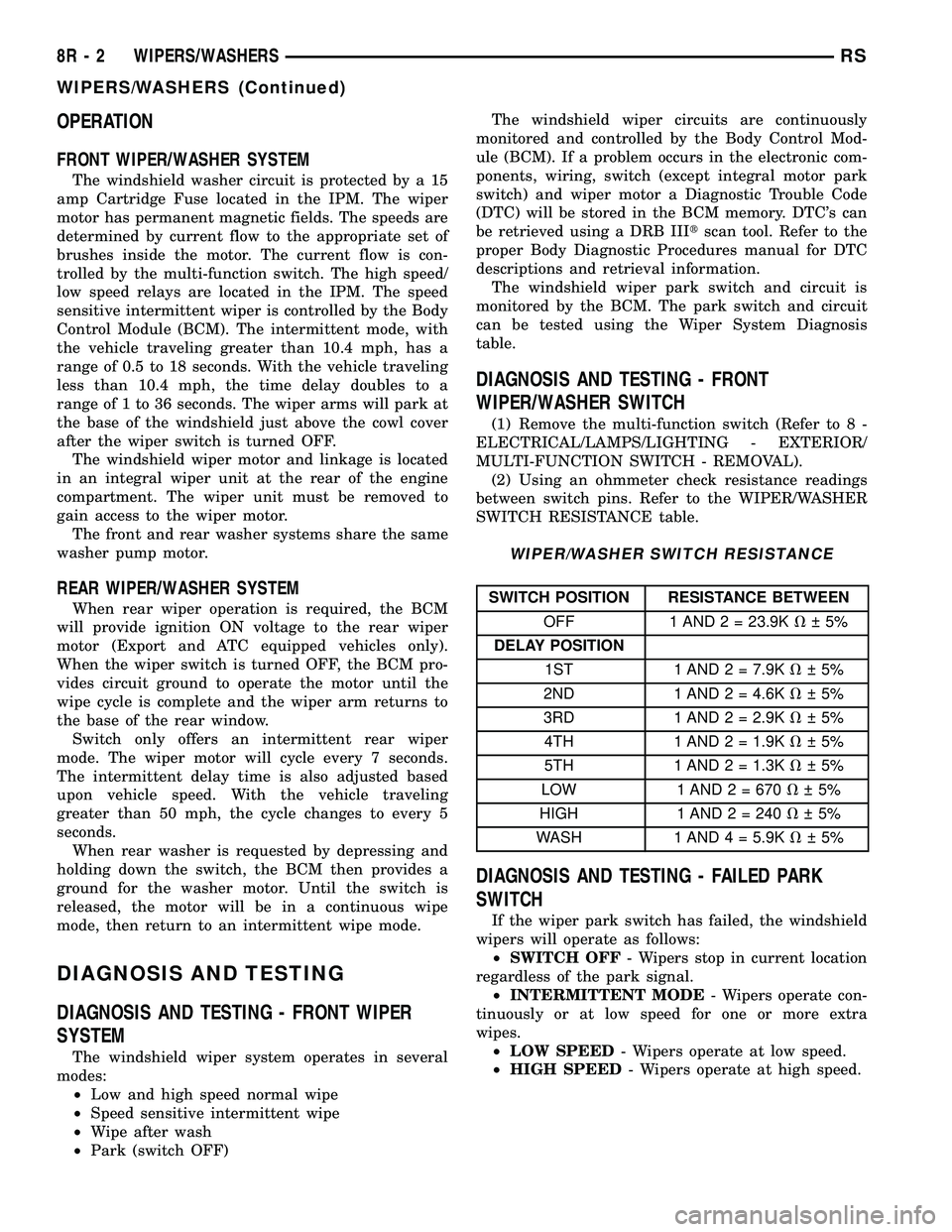
OPERATION
FRONT WIPER/WASHER SYSTEM
The windshield washer circuit is protected by a 15
amp Cartridge Fuse located in the IPM. The wiper
motor has permanent magnetic fields. The speeds are
determined by current flow to the appropriate set of
brushes inside the motor. The current flow is con-
trolled by the multi-function switch. The high speed/
low speed relays are located in the IPM. The speed
sensitive intermittent wiper is controlled by the Body
Control Module (BCM). The intermittent mode, with
the vehicle traveling greater than 10.4 mph, has a
range of 0.5 to 18 seconds. With the vehicle traveling
less than 10.4 mph, the time delay doubles to a
range of 1 to 36 seconds. The wiper arms will park at
the base of the windshield just above the cowl cover
after the wiper switch is turned OFF.
The windshield wiper motor and linkage is located
in an integral wiper unit at the rear of the engine
compartment. The wiper unit must be removed to
gain access to the wiper motor.
The front and rear washer systems share the same
washer pump motor.
REAR WIPER/WASHER SYSTEM
When rear wiper operation is required, the BCM
will provide ignition ON voltage to the rear wiper
motor (Export and ATC equipped vehicles only).
When the wiper switch is turned OFF, the BCM pro-
vides circuit ground to operate the motor until the
wipe cycle is complete and the wiper arm returns to
the base of the rear window.
Switch only offers an intermittent rear wiper
mode. The wiper motor will cycle every 7 seconds.
The intermittent delay time is also adjusted based
upon vehicle speed. With the vehicle traveling
greater than 50 mph, the cycle changes to every 5
seconds.
When rear washer is requested by depressing and
holding down the switch, the BCM then provides a
ground for the washer motor. Until the switch is
released, the motor will be in a continuous wipe
mode, then return to an intermittent wipe mode.
DIAGNOSIS AND TESTING
DIAGNOSIS AND TESTING - FRONT WIPER
SYSTEM
The windshield wiper system operates in several
modes:
²Low and high speed normal wipe
²Speed sensitive intermittent wipe
²Wipe after wash
²Park (switch OFF)The windshield wiper circuits are continuously
monitored and controlled by the Body Control Mod-
ule (BCM). If a problem occurs in the electronic com-
ponents, wiring, switch (except integral motor park
switch) and wiper motor a Diagnostic Trouble Code
(DTC) will be stored in the BCM memory. DTC's can
be retrieved using a DRB IIItscan tool. Refer to the
proper Body Diagnostic Procedures manual for DTC
descriptions and retrieval information.
The windshield wiper park switch and circuit is
monitored by the BCM. The park switch and circuit
can be tested using the Wiper System Diagnosis
table.
DIAGNOSIS AND TESTING - FRONT
WIPER/WASHER SWITCH
(1) Remove the multi-function switch (Refer to 8 -
ELECTRICAL/LAMPS/LIGHTING - EXTERIOR/
MULTI-FUNCTION SWITCH - REMOVAL).
(2) Using an ohmmeter check resistance readings
between switch pins. Refer to the WIPER/WASHER
SWITCH RESISTANCE table.
WIPER/WASHER SWITCH RESISTANCE
SWITCH POSITION RESISTANCE BETWEEN
OFF 1 AND 2 = 23.9KV 5%
DELAY POSITION
1ST 1 AND 2 = 7.9KV 5%
2ND 1 AND 2 = 4.6KV 5%
3RD 1 AND 2 = 2.9KV 5%
4TH 1 AND 2 = 1.9KV 5%
5TH 1 AND 2 = 1.3KV 5%
LOW 1 AND 2 = 670V 5%
HIGH 1 AND2=240V 5%
WASH 1 AND 4 = 5.9KV 5%
DIAGNOSIS AND TESTING - FAILED PARK
SWITCH
If the wiper park switch has failed, the windshield
wipers will operate as follows:
²SWITCH OFF- Wipers stop in current location
regardless of the park signal.
²INTERMITTENT MODE- Wipers operate con-
tinuously or at low speed for one or more extra
wipes.
²LOW SPEED- Wipers operate at low speed.
²HIGH SPEED- Wipers operate at high speed.
8R - 2 WIPERS/WASHERSRS
WIPERS/WASHERS (Continued)
Page 583 of 2339
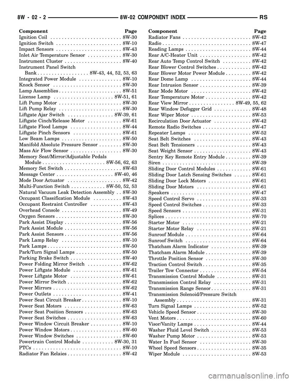
Component Page
Ignition Coil......................... 8W-30
Ignition Switch....................... 8W-10
Impact Sensors....................... 8W-43
Inlet Air Temperature Sensor............ 8W-30
Instrument Cluster.................... 8W-40
Instrument Panel Switch
Bank.................. 8W-43, 44, 52, 53, 63
Integrated Power Module............... 8W-10
Knock Sensor........................ 8W-30
Lamp Assemblies...................... 8W-51
License Lamp..................... 8W-51, 61
Lift Pump Motor...................... 8W-30
Lift Pump Relay...................... 8W-30
Liftgate Ajar Switch................ 8W-39, 61
Liftgate Cinch/Release Motor............ 8W-61
Liftgate Flood Lamps.................. 8W-44
Liftgate Pinch Sensors................. 8W-61
Low Beam Lamps..................... 8W-50
Manifold Absolute Pressure Sensor........ 8W-30
Mass Air Flow Sensor.................. 8W-30
Memory Seat/Mirror/Adjustable Pedals
Module...................... 8W-56, 62, 63
Memory Set Switch.................... 8W-63
Message Center.................... 8W-40, 46
Mode Door Actuator................... 8W-42
Multi-Function Switch............ 8W-50, 52, 53
Natural Vacuum Leak Detection Assembly . . 8W-30
Occupant Classification Module.......... 8W-43
Occupant Restraint Controller........... 8W-43
Overhead Console..................... 8W-49
Oxygen Sensors....................... 8W-30
Park Assist Display.................... 8W-56
Park Assist Module.................... 8W-56
Park Assist Sensors.................... 8W-56
Park Lamp Relay..................... 8W-10
Park Lamps.......................... 8W-50
Park/Turn Signal Lamps................ 8W-50
Parking Brake Switch.................. 8W-40
Power Folding Mirror Switch............ 8W-62
Power Liftgate Module................. 8W-61
Power Liftgate Motor.................. 8W-61
Power Mirror Switch................... 8W-62
Power Mirrors........................ 8W-62
Power Outlets........................ 8W-41
Power Seat Circuit Breaker.............. 8W-10
Power Seat Motors.................... 8W-63
Power Seat Position Sensors............. 8W-63
Power Seat Switches................... 8W-63
Power Window Circuit Breaker........... 8W-10
Power Window Motors.................. 8W-60
Power Window Switches................ 8W-60
Powertrain Control Module........... 8W-30, 31
PTCs............................... 8W-10
Radiator Fan Relaies................... 8W-42Component Page
Radiator Fans........................ 8W-42
Radio............................... 8W-47
Reading Lamps....................... 8W-44
Rear A/C-Heater Unit.................. 8W-42
Rear Auto Temp Control Switch.......... 8W-42
Rear Blower Control Switches............ 8W-42
Rear Blower Motor Power Module......... 8W-42
Rear Dome Lamp..................... 8W-44
Rear Intrusion Sensor.................. 8W-39
Rear Mode Motor..................... 8W-42
Rear Temperature Motor................ 8W-42
Rear View Mirror................ 8W-49, 55, 62
Rear Window Defogger Grid............. 8W-48
Rear Wiper Motor..................... 8W-53
Recirculation Door Actuator............. 8W-42
Remote Radio Switches................. 8W-47
Repeater Lamps...................... 8W-52
Seat Belt Switches.................... 8W-43
Seat Belt Tensioners................... 8W-43
Seat Weight Sensor.................... 8W-43
Sentry Key Remote Entry Module......... 8W-39
Siren............................... 8W-39
Sliding Door Control Modules............ 8W-61
Sliding Door Latch Sensing Switches...... 8W-61
Sliding Door Lock Motors............... 8W-61
Sliding Door Motors................... 8W-61
Speakers............................ 8W-47
Speed Control Servo................... 8W-33
Speed Control Switches................. 8W-33
Speed Sensors........................ 8W-31
Splices.............................. 8W-70
Starter Motor........................ 8W-21
Starter Motor Relay................... 8W-21
Sunroof Module....................... 8W-64
Sunroof Switch....................... 8W-64
Thatcham Alarm Indicator.............. 8W-39
Thatcham Alarm Module................ 8W-39
Throttle Position Sensor................ 8W-30
Traction Control Switch................. 8W-35
Trailer Tow Connector.................. 8W-54
Transmission Control Module............ 8W-31
Transmission Control Relay............. 8W-31
Transmission Range Sensor.............. 8W-31
Transmission Solenoid/Pressure Switch
Assembly.......................... 8W-31
Turn Signal Lamps.................... 8W-52
Vehicle Speed Sensor................... 8W-30
Vent Motors.......................... 8W-60
Visor/Vanity Lamps.................... 8W-44
Washer Fluid Level Switch.............. 8W-53
Washer Pump Motor................... 8W-53
Water In Fuel Sensor.................. 8W-30
Wheel Speed Sensors................... 8W-35
Wiper Module........................ 8W-53
8W - 02 - 2 8W-02 COMPONENT INDEXRS