rear lamp CHRYSLER VOYAGER 2005 Owner's Guide
[x] Cancel search | Manufacturer: CHRYSLER, Model Year: 2005, Model line: VOYAGER, Model: CHRYSLER VOYAGER 2005Pages: 2339, PDF Size: 59.69 MB
Page 202 of 2339
(1) Make sure all hydraulic fluid lines are installed
and properly torqued.
(2) Connect the DRBIIItscan tool to the diagnos-
tics connector. The diagnostic connector is located
under the lower steering column cover to the left of
the steering column.
(3) Using the DRB, check to make sure the CAB
does not have any fault codes stored. If it does, clear
them using the DRB.
WARNING: WHEN BLEEDING THE BRAKE SYSTEM
WEAR SAFETY GLASSES. A CLEAR BLEED TUBE
MUST BE ATTACHED TO THE BLEEDER SCREWS
AND SUBMERGED IN A CLEAR CONTAINER FILLED
PART WAY WITH CLEAN BRAKE FLUID. DIRECT
THE FLOW OF BRAKE FLUID AWAY FROM YOUR-
SELF AND THE PAINTED SURFACES OF THE VEHI-
CLE. BRAKE FLUID AT HIGH PRESSURE MAY
COME OUT OF THE BLEEDER SCREWS WHEN
OPENED.
(4) Bleed the base brake system using the stan-
dard pressure or manual bleeding procedure. (Refer
to 5 - BRAKES - BASE - STANDARD PROCEDURE)
(5) Using the DRB, select ANTILOCK BRAKES,
followed by MISCELLANEOUS, then BLEED
BRAKES. Follow the instructions displayed. When
the scan tool displays TEST COMPLETED, discon-
nect the scan tool and proceed.
(6) Bleed the base brake system a second time.
Check brake fluid level in the reservoir periodically
to prevent emptying, causing air to enter the hydrau-
lic system.
(7) Fill the master cylinder reservoir to the full
level.
(8) Test drive the vehicle to be sure the brakes are
operating correctly and that the brake pedal does not
feel spongy.
SPECIFICATIONS
ABS FASTENER TORQUE
Refer to BRAKE FASTENER TORQUE. (Refer to 5
- BRAKES - BASE - SPECIFICATIONS)
TONE WHEEL RUNOUT
DESCRIPTION SPECIFICATION
Front Tone Wheel
Maximum Runout0.15 mm (0.006 in.)
Rear Tone Wheel
Maximum Runout0.15 mm (0.006 in.)
WHEEL SPEED SENSOR AIR GAP
DESCRIPTION SPECIFICATION
Front Sensor0.35 ± 1.20 mm
0.014 ± 0.047 in.
Rear Sensor0.40 ± 1.20 mm
0.016 ± 0.047 in.
FRONT WHEEL SPEED
SENSOR
REMOVAL
(1)Raise vehicle. (Refer to LUBRICATION & MAIN-
TENANCE/HOISTING - STANDARD PROCEDURE)
(2) Remove the tire and wheel assembly.
(3) Remove the sensor cable routing clamp screws.
CAUTION: When disconnecting the wheel speed
sensor from vehicle wiring harness, be careful not
to damage pins on connector
(4) Remove speed sensor cable grommets from
intermediate bracket on strut.
(5) Disconnect speed sensor cable from vehicle wir-
ing harness behind fender well shield.
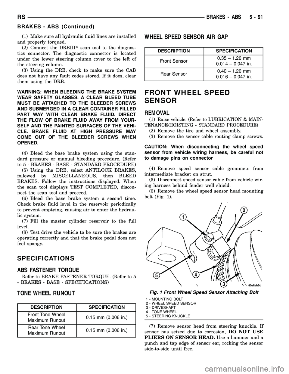
(6) Remove the wheel speed sensor head mounting
bolt (Fig. 1).
(7) Remove sensor head from steering knuckle. If
sensor has seized due to corrosion,DO NOT USE
PLIERS ON SENSOR HEAD.Use a hammer and a
punch and tap edge of sensor ear, rocking the sensor
side-to-side until free.
Fig. 1 Front Wheel Speed Sensor Attaching Bolt
1 - MOUNTING BOLT
2 - WHEEL SPEED SENSOR
3 - DRIVESHAFT
4 - TONE WHEEL
5 - STEERING KNUCKLE
RSBRAKES - ABS5-91
BRAKES - ABS (Continued)
Page 203 of 2339
(8) Remove front wheel speed sensor from vehicle.
INSTALLATION
CAUTION: Proper installation of wheel speed sen-
sor cables is critical to continued system operation.
Be sure that cables are installed in retainers. Fail-
ure to install cables in retainers as shown in this
section may result in contact with moving parts and
over extension of cables, resulting in an open cir-
cuit.
(1) Connect the front wheel speed sensor cable to
the vehicle wiring harness connector. Be sure speed
sensor cable connector is fully seated and locked into
vehicle wiring harness connector.
(2) Install the bolts attaching the routing clamps
to the body of the vehicle. Tighten the bolts to a
torque of 14 N´m (125 in. lbs.).
(3) Insert speed sensor cable grommets into inter-
mediate bracket on strut.
(4) Install the wheel speed sensor head mounting
bolt (Fig. 1). Tighten the bolt to a torque of 13 N´m
(115 in. lbs.)
(5) Install the wheel and tire assembly on vehicle.
(6) Lower vehicle.
(7) Road test vehicle to ensure proper operation of
the base and ABS brake systems.
REAR WHEEL SPEED SENSOR
-AWD
REMOVAL
(1) Raise vehicle. (Refer to LUBRICATION &
MAINTENANCE/HOISTING - STANDARD PROCE-
DURE)
CAUTION: When disconnecting speed sensor cable
from vehicle wiring harness be careful not to dam-
age pins on the electrical connectors. Also, inspect
connectors for any signs of previous damage.
(2) Remove grommet from floor pan of vehicle and
disconnect speed sensor cable connector from vehicle
wiring harness.
CAUTION: When removing rear wheel speed sensor
cable from routing clips, be sure not to damage the
routing clips. Routing clips that are molded onto
the brake hose will require replacement of the brake
hose if damaged during removal or installation of
the speed sensor cable.
(3) Carefully remove speed sensor cable from
press-in routing clips along brake hose and tubing.(4) Remove bolt securing wheel speed sensor cable
metal clip to rear of axle. Remove metal clip from
cable if necessary.
CAUTION: If speed sensor head has seized due to
corrosion, do not use pliers on speed sensor head
in an attempt to remove it. Use a hammer and a
punch and tap mounting flange edge side-to-side,
rocking the sensor until free.
(5) Remove wheel speed sensor head attaching
bolt.
(6) Remove wheel speed sensor head from the axle,
and remove sensor from vehicle.
INSTALLATION
CAUTION: Proper installation of wheel speed sen-
sor cables is critical to continued system operation.
Be sure that cables are installed in retainers. Fail-
ure to install cables in retainers as indicated may
result in contact with moving parts or over-exten-
sion of cables, resulting in an open circuit.
(1) Install wheel speed sensor head in axle flange.
CAUTION: Prior to installing the speed sensor head
attaching bolt, the plastic anti-rotation pin must be
fully seated into the bearing flange.
(2) Install wheel speed sensor head attaching bolt.
Tighten bolt to a torque 10 N´m (90 in. lbs.).
(3) Check the air gap between the face of the
wheel speed sensor and the top surface of the tone
wheel. (Refer to 5 - BRAKES - SPECIFICATIONS)
CAUTION: When installing wheel speed sensor
cable in the routing clips on rear brake flex hose,
be sure not to damage the routing clips. Routing
clips are molded onto the hose and will require
replacement of the brake hose if damaged.
(4) Install speed sensor cable under leaf spring
onto brake hose and tubing utilizing routing clips to
secure it in place.
(5) Install metal routing clip on speed sensor cable
and mount it to rear of axle with mounting bolt.
Tighten mounting bolt to 16 N´m (140 in. lbs.).
(6) Connect wheel speed sensor cable to vehicle
wiring harness.Be sure speed sensor cable con-
nector is fully seated and locked into vehicle
wiring harness connector.
(7) Install speed sensor cable grommet into the
floor pan, being sure the grommet is fully seated into
the access hole.
(8) Lower vehicle.
(9) Road test vehicle to ensure proper operation of
the base and ABS braking systems.
5 - 92 BRAKES - ABSRS
FRONT WHEEL SPEED SENSOR (Continued)
Page 221 of 2339
OPERATION
OPERATION - COOLING SYSTEM
The engine cooling systems primary purpose is to
maintain engine temperature in a range that will
provide satisfactory engine performance and emission
levels under all expected driving conditions. It also
provides hot water (coolant) for heater performance
and cooling for automatic transmission oil. It does
this by transferring heat from engine metal to cool-
ant, moving this heated coolant to the radiator, and
then transferring this heat to the ambient air.
²When engine is cold: thermostat is closed, cool-
ing system has no flow through the radiator. The
coolant bypass flows through the engine only.
²When engine is warm: thermostat is open, cool-
ing system has bypass flow and coolant flow through
radiator.
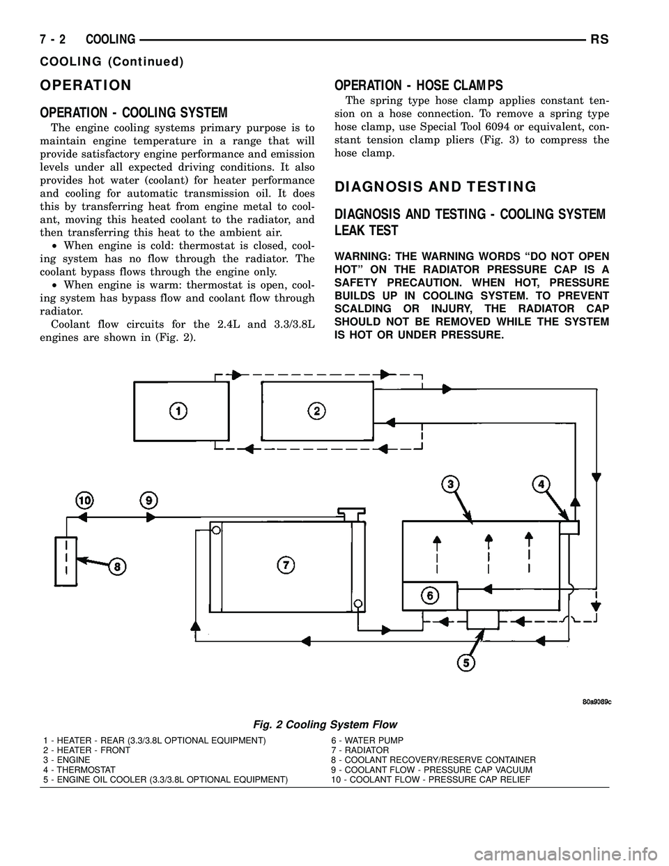
Coolant flow circuits for the 2.4L and 3.3/3.8L
engines are shown in (Fig. 2).
OPERATION - HOSE CLAMPS
The spring type hose clamp applies constant ten-
sion on a hose connection. To remove a spring type
hose clamp, use Special Tool 6094 or equivalent, con-
stant tension clamp pliers (Fig. 3) to compress the
hose clamp.
DIAGNOSIS AND TESTING
DIAGNOSIS AND TESTING - COOLING SYSTEM
LEAK TEST
WARNING: THE WARNING WORDS ªDO NOT OPEN
HOTº ON THE RADIATOR PRESSURE CAP IS A
SAFETY PRECAUTION. WHEN HOT, PRESSURE
BUILDS UP IN COOLING SYSTEM. TO PREVENT
SCALDING OR INJURY, THE RADIATOR CAP
SHOULD NOT BE REMOVED WHILE THE SYSTEM
IS HOT OR UNDER PRESSURE.
Fig. 2 Cooling System Flow
1 - HEATER - REAR (3.3/3.8L OPTIONAL EQUIPMENT) 6 - WATER PUMP
2 - HEATER - FRONT 7 - RADIATOR
3 - ENGINE 8 - COOLANT RECOVERY/RESERVE CONTAINER
4 - THERMOSTAT 9 - COOLANT FLOW - PRESSURE CAP VACUUM
5 - ENGINE OIL COOLER (3.3/3.8L OPTIONAL EQUIPMENT) 10 - COOLANT FLOW - PRESSURE CAP RELIEF
7 - 2 COOLINGRS
COOLING (Continued)
Page 280 of 2339
CHIME/BUZZER
TABLE OF CONTENTS
page page
CHIME/BUZZER
DESCRIPTION..........................1
OPERATION............................1
WARNING.............................2
DIAGNOSIS AND TESTING - CHIME SYSTEM . . 2
PARK ASSIST DISPLAY
DESCRIPTION..........................3
OPERATION............................3
REMOVAL.............................4
INSTALLATION..........................4PARK ASSIST MODULE
DESCRIPTION..........................4
OPERATION............................5
REMOVAL.............................5
INSTALLATION..........................6
PARK ASSIST SENSOR
DESCRIPTION..........................6
OPERATION............................6
REMOVAL.............................6
INSTALLATION..........................6
CHIME/BUZZER
DESCRIPTION
The chime/buzzer system provides the driver with
warning chimes for:
²Seat Belt
²Exterior Lamps ON
²Key-In Ignition
²Engine Temperature Critical
²Turn Signals ON
²Dome Lamp ON
²Low Oil Pressure
²High Speed Warning
²Warning Lamp Announcement
²Key-In Accessory
²Low/High Tire Pressure
²Service Tire Pressure Monitor (TPM)
HIGH SPEED WARNING - EXPORT
The chime will sound, acting as a warning to the
driver that the vehicle speed has exceeded 120 3
Kp/h (75 2 mph).
Refer to the proper body diagnostic information
diagnosis and testing with a scan tool.
PARK ASSIST SYSTEM
The Park Assist System is an electronic parking
aid that alerts the driver to obstacles which are
located immediately behind the vehicle. Objects are
sensed using ultrasonic sound waves. When an object
is detected, the system will give the driver visual and
audible warnings. The system is customer program-
mable through the Electronic Vehicle Information
Center (EVIC) but will be enabled from the factory
as a default.
The major components of the park assist system
are:²Park Assist Module- supplies voltage to the
object detection sensors and park assist display. It
triggers the sensors, analyzes the echo delay times
and calculates obstacle distances. It sends display
information to the park assist display, performs sys-
tem diagnostics, and communicates via the Program-
mable Communication Interface (PCI) date bus
network.
²Park Assist Sensors- there are four sensors
located in the rear bumper that generate ultrasonic
pulses when triggered by the park assist module. The
sensors signal the park assist module when reflected
ultrasonic pulses are received.
²Park Assist Display- there are sixteen Light
Emitting Diode (LED) indicators which provide indi-
cation of relative distance to obstacles. When the sys-
tem is engaged and no obstacles are detected, the
two outermost yellow LED's are lit at reduced bright-
ness to show the system is working. As the distance
to a detected obstacle decreases, more yellow LED's
towards the center of the display illuminate.
For diagnosis and testing of the park assist sys-
tem, use a scan tool and the appropriate body diag-
nostic information.
OPERATION
Refer to the proper Body Diagnostic Procedures
manual for complete chime/buzzer operation and con-
ditions for operation.
HIGH SPEED WARNING - EXPORT
When the vehicle speed sensor sees 120 3 Km/h
(75 2 mph), it sends a PCI data bus message to the
Body Control Module (BCM). The BCM then turns on
the chime to let the driver know that the vehicle has
reached a speed greater than 120 3 Km/h (75 2
mph). This audible message will continue until the
vehicle is slowed below the predetermined speed.
RSCHIME/BUZZER8B-1
Page 282 of 2339
NO FASTEN SEAT BELT LAMP WHEN IGNITION
SWITCH IS TURNED ON.
(1) Check for burned out lamp.
(2) Using a voltmeter check for voltage at the clus-
ter connector:
(a) Pin 2 of the mechanical instrument cluster
for battery feed.
(b) Pin 11 of the mechanical instrument cluster
for ignition voltage.
(3) Repair as necessary.
FASTEN SEAT BELT LAMP OR TONE CONTINUES
FOR MORE THAN 10 SECONDS AFTER SEAT
BELTS ARE FASTENED AND DRIVER'S DOOR IS
CLOSED.
Refer to the proper Body Diagnostic Procedures
manual.
NO TONE WHEN PARK OR HEADLAMPS ARE ON
AND DRIVER'S DOOR IS OPEN.
Make sure ignition is in lock position with the key
removed.
(1) Check the BCM DTC's and BCM sensors to
verify the door is open. Repair as necessary.
(2) Actuate Chime (BCM actuates).
(3) Inspect BCM connectors and wires for proper
connection.
(4) Measure with a voltmeter the voltage (12v) on
BCM connector (PX2) pin 34 with harness connected.
(5) Check BCM sensors to verify headlamp switch
position.
PARK ASSIST DISPLAY
DESCRIPTION
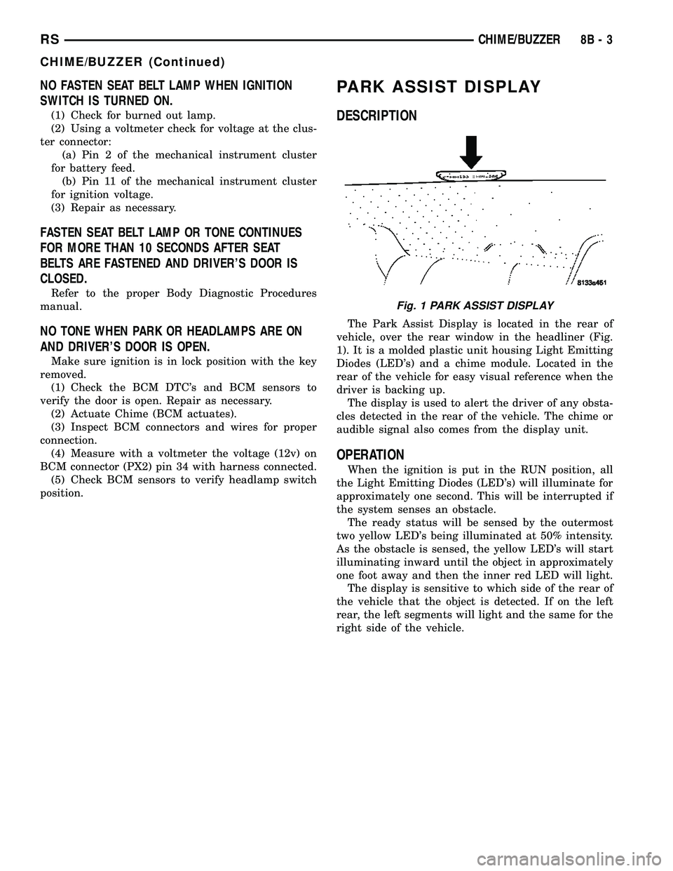
The Park Assist Display is located in the rear of
vehicle, over the rear window in the headliner (Fig.
1). It is a molded plastic unit housing Light Emitting
Diodes (LED's) and a chime module. Located in the
rear of the vehicle for easy visual reference when the
driver is backing up.
The display is used to alert the driver of any obsta-
cles detected in the rear of the vehicle. The chime or
audible signal also comes from the display unit.
OPERATION
When the ignition is put in the RUN position, all
the Light Emitting Diodes (LED's) will illuminate for
approximately one second. This will be interrupted if
the system senses an obstacle.
The ready status will be sensed by the outermost
two yellow LED's being illuminated at 50% intensity.
As the obstacle is sensed, the yellow LED's will start
illuminating inward until the object in approximately
one foot away and then the inner red LED will light.
The display is sensitive to which side of the rear of
the vehicle that the object is detected. If on the left
rear, the left segments will light and the same for the
right side of the vehicle.
Fig. 1 PARK ASSIST DISPLAY
RSCHIME/BUZZER8B-3
CHIME/BUZZER (Continued)
Page 288 of 2339
The BCM utilizes integrated circuitry and informa-
tion carried on the Programmable Communications
Interface (PCI) data bus network along with many
hard wired inputs to monitor many sensor and
switch inputs throughout the vehicle. In response to
those inputs, the internal circuitry and programming
of the BCM allow it to control and integrate many
electronic functions and features of the vehicle
through both hard wired outputs and the transmis-
sion of electronic message outputs to other electronic
modules in the vehicle over the PCI data bus.
OPERATION
The Body Control Module (BCM) supplies vehicle
occupants with visual and audible information and
controls various vehicle functions. To provide and
receive information, the BCM is interfaced to the
vehicle's serial bus communications network, referred
to as the Programmable Communications Interface
(PCI) bus.
This network consists of the;
²Powertrain Control Module (PCM)
²Transmission Control Module (TCM)
²Mechanical Instrument Cluster (MIC)
²Occupant Restraint Controller (ORC)
²Compass/Mini-Trip Computer (CMTC)
²Electronic Vehicle Information Center (EVIC)
²Controller Antilock Brake (CAB)
²HVAC Control Module
²Sliding Door Control Modules (driver and pas-
senger side doors)
²Power Liftgate Module (PLG)
²Audio system equipped with RAZ, RBU, RBK,
and RBB radios.
²Sentry Key Remote Entry Module (SKREEM).
²Side Impact Airbag Control Module (SIACM)²Memory Seat Module (MSM)
²Sentry Key Immobilizer Module (SKIM)
The BCM is operational when battery power is
supplied to the module.
The BCM provides the following features:
²Power Door Locks
²Automatic Door Locks
²Battery Protection - The BCM will automatically
turn off all exterior lamps after 3 minutes, and all
interior lamps after 15 minutes after the ignition is
turned off, if they are not turned off by the driver.
²Chime Control
²Compass/Mini-Trip support.
²Interior Lighting (Courtesy/Reading Lamps)
²BCM Diagnostic Reporting
²Electronic Liftgate Release (with Power Door
Locks)
²Exterior Lighting
²Headlamp Time Delay (with/without Automatic
Headlamps)
²Illuminated Entry
²Fade to Off Interior Lamps - This feature dims
the interior lighting (courtesy lamps) gradually if the
BCM does not receive any new inputs that would
cause the interior lamps to remain on.
²Pulse Width Modulated Instrument Panel Dim-
ming
²Door Lock Inhibit - This feature disables the
door lock functions if the key is in the ignition and
either front door is ajar. Pressing the Remote Keyless
Entry (RKE) lock/unlock button under these condi-
tions result in normal lock/unlock activation.
The BCM has the ability to LEARN additional fea-
tures in the vehicle, provided the appropriate switch
input and PCI data bus messages are received. Refer
to the LEARNED FEATURES table.
LEARNED FEATURES
FEATURE LEARNING KEY
REAR WIPER CONTROL ON HVAC CONTROL ON
INSTRUMENT PANELPCI BUS MESSAGE RECEIVED FROM HVAC
CONTROL
AUTOMATIC HEADLAMPS PCI MESSAGE FROM OVERHEAD OR HEADLAMP
SWITCH POSITION (AUTO)
REMOTE KEYLESS ENTRY SKREEM MESSAGE RECEIVED FROM MODULE
FRONT FOG LAMPS HEADLAMP SWITCH POSITION (PARK W/FRONT
FOG LAMPS)
POWER SLIDING DOOR PCI IFR RECEIVED FROM MODULE
THE BCM HAS FOUR SWITCH INPUTS FOR THE POWER SLIDING DOOR FEATURE; LOCATED IN THE
OVERHEAD CONSOLE ARE THE LEFT AND RIGHT SIDE SLIDING DOOR SWITCHES TO ACTIVATE EITHER
OR BOTH SLIDING DOORS UNDER THE PROPER CONDITIONS. ALSO ARE B-PILLAR SWITCHES LOCATED
ON THE LEFT AND RIGHT B-PILLAR POSTS.
POWER LIFTGATE PCI IFR RECEIVED FROM MODULE
RSELECTRONIC CONTROL MODULES8E-3
BODY CONTROL MODULE (Continued)
Page 292 of 2339
FRONT CONTROL MODULE
DESCRIPTION
The Front Control Module (FCM) is a micro con-
troller based module located in the engine compart-
ment. The FCM mates to the Power Distribution
Center (PDC) to form the Integrated Power Module
(IPM). The IPM connects directly to the battery and
provides the primary means of circuit protection and
power distribution for all vehicle electrical systems.
The FCM controls power to some of these vehicle sys-
tems electrical and electromechanical loads based on
inputs received from hard wired switch inputs and
data received on the Programmable Communications
Interface (PCI) data bus.
For information on the IPM, (Refer to 8 - ELEC-
TRICAL/POWER DISTRIBUTION/INTEGRATED
POWER MODULE - DESCRIPTION)
OPERATION
As messages are sent over the Programmable Com-
munications Interface (PCI) data bus, the Front Con-
trol Module (FCM) reads these messages and controls
power to some of the vehicles electrical systems by
completing the circuit to ground (low side driver) or
completing the circuit to 12 volt power (high side
driver).
The following functions arecontrolledby the
Front Control Module:
²Accessory Relay Actuation
²Brake Transmission Shift Interlock Functions
(BTSI - gas engine only)
²Diesel Cabin Heater (Diesel Engine Vehicles)
²Electronic Back Light (EBL) Rear Defogger
²Front and Rear Blower Motor Relay Actuation
²Front Fog Lamp Relay Actuation
²Washer Motor (front and rear)
²Front Windshield Wiper ªHIº & ªLOº Relay
Actuation
²Front Windshield Wiper ªONº Relay Actuation
²Headlamp Power with Voltage Regulation
²Horn Relay Actuation
²Headlamp Washer Relay Actuation (IF
EQUIPPED - EXPORT ONLY)
²Name Brand Speaker (NBS) Relay Actuation
²Park Lamp Relay Actuation
The following inputs areReceived/Monitoredby
the Front Control Module:
²Ambient Temperature Sensing
²Back-Up switch
²Brake Fluid Level
²B+ Connection Detection
²Engine Crank Signal (Diesel Engine Vehicles)
²Horn Input
²Ignition Switch Start Only
²Ignition Switch Run and Start Only²Stop Lamp Sense
²Washer Fluid Level
²Windshield Wiper Park
DIAGNOSIS AND TESTING
FRONT CONTROL MODULE
The Front Control Module (FCM) is a printed cir-
cuit board based module with a on-board micro-pro-
cessor. The FCM interfaces with other electronic
modules in the vehicle via the Programmable Com-
munications Interface (PCI) data bus. In order to
obtain conclusive testing the PCI data bus and all of
the electronic modules that provide inputs to, or
receive outputs from the FCM must be checked. All
PCI communication faults must be resolved prior to
further diagnosing any front control module related
issues.
The FCM was designed to be diagnosed with an
appropriate diagnostic scan tool, such as the DRB
IIIt. The most reliable, efficient, and accurate means
to diagnose the front control module requires the use
of a DRB IIItscan tool and the proper Body Diag-
nostic Procedures manual.
Before any testing of the FCM is attempted, the
battery should be fully charged and all wire harness
and ground connections inspected around the affected
areas on the vehicle.
REMOVAL
(1) Disconnect and isolate the negative and posi-
tive battery cables from the battery.
(2) Remove the battery (Refer to 8 - ELECTRI-
CAL/BATTERY SYSTEM/BATTERY - REMOVAL).
(3) Using a long flat-bladed screwdriver, gently
twist the Integrated Power Module (IPM) retaining
clip outboard to free the IPM from its mounting
bracket (Fig. 5). Rotate IPM upward to access the
Front Control Module (FCM) retaining screws.
(4) Remove the front control module retaining
screws.
(5) Pull the FCM straight from the IPM assembly
to disconnect the electrical connector (Fig. 6) and
remove the FCM from the vehicle.
INSTALLATION
NOTE: Front Control Module must be programmed
to the correct radio EQ curve using the DRB IIIT.
This will ensure that the audio system is operating
correctly.
(1) Install the Front Control Module (FCM) in the
Integrated Power Module (IPM) assembly by pushing
the 49-way electrical connector straight in.
RSELECTRONIC CONTROL MODULES8E-7
Page 347 of 2339
OPERATION
When the rear window defogger button is
depressed to the On position, current is directed to
the rear defogger grid lines and the heated power
mirrors (if equipped). The heated grid lines heat the
glass to help clear the rear window and side mirror
surfaces of fog or frost.
The electric backlight (EBL) system is controlled
by a momentary switch located in the A/C-heater
control on the instrument panel. A yellow indicator in
the switch will illuminate to indicate when the sys-
tem is turned on. The integrated power module (IPM)
contains the EBL system control circuitry.
NOTE: The rear window defogger turns off automat-
ically after approximately 10 minutes of initial oper-
ation. Each following activation cycle of the
defogger system will last approximately five min-
utes.
The EBL system will be automatically turned off
after a programmed time interval of about ten min-
utes. After the initial time interval has expired, if the
defogger switch is turned on again during the same
ignition cycle, the defogger system will automatically
turn off after about five minutes.
The EBL system will automatically shut off if the
ignition switch is turned to the Off position, or it can
be turned off manually by depressing the defogger
switch a second time.
DIAGNOSIS AND TESTING
ELECTRIC BACKLIGHT (EBL) SYSTEM
NOTE: Illumination of the defogger switch indicator
lamp means that there is electrical current available
at the output of the rear window defogger logic cir-
cuitry, but does not confirm that the electrical cur-
rent is reaching the rear glass heating grid lines.
NOTE: For circuit descriptions and diagrams of the
rear window defogger system, refer to 8W - WIRING
DIAGRAM INFORMATION.
Operation of the electrical backlight (EBL) system
can be confirmed by the following:(1) Turn the ignition switch to the On position. Set
the defogger switch in the On position. The rear win-
dow defogger operation can be checked by feeling the
rear window glass. A distinct difference in tempera-
ture between the grid lines and the adjacent clear
glass can be detected within three to four minutes of
operation.
(2) If a temperature difference is not detected, use
a 12-volt DC voltmeter and contact the rear glass
heating grid terminal B with the negative lead, and
terminal A with the positive lead (Fig. 2). The volt-
meter should read battery voltage. If the voltmeter
does not read battery voltage, check the following:
²Confirm that the ignition switch is in the On
position.
²Make sure that the rear glass heating grid feed
wire and ground wire are connected to the terminals.
Confirm that the ground wire has continuity to
ground.
²Check that fuse 13 (40 amp) in the integrated
power module (IPM) is OK. The fuse must be tight in
it's receptacle and all electrical connections must be
secure.
(3) When the above steps have been completed and
the rear glass heating grid is still inoperative, one or
more of the following is faulty. It may be necessary to
connect a DRBIIItscan tool to perform further diag-
nostics. Refer to Body Diagnostic Procedures.
²Rear window defogger switch in the A/C-heater
control.
²J1850 bus communication between the A/C-
heater control and the front control module (FCM).
²Rear window defogger (EBL) relay in the IPM.
²Rear window defogger (EBL) relay control circu-
ity in the IPM.
²Check for a loose wire connector or a wire
pushed out of a connector.
²Rear window grid lines (all grid lines would
have to be broken, or the power feed or ground wire
not connected, for the entire heating grid to be inop-
erative).
(4) If the system operation has been verified but
defogger switch LED indicator does not illuminate,
replace the A/C-heater control.
8G - 2 HEATED GLASSRS
HEATED GLASS (Continued)
Page 349 of 2339
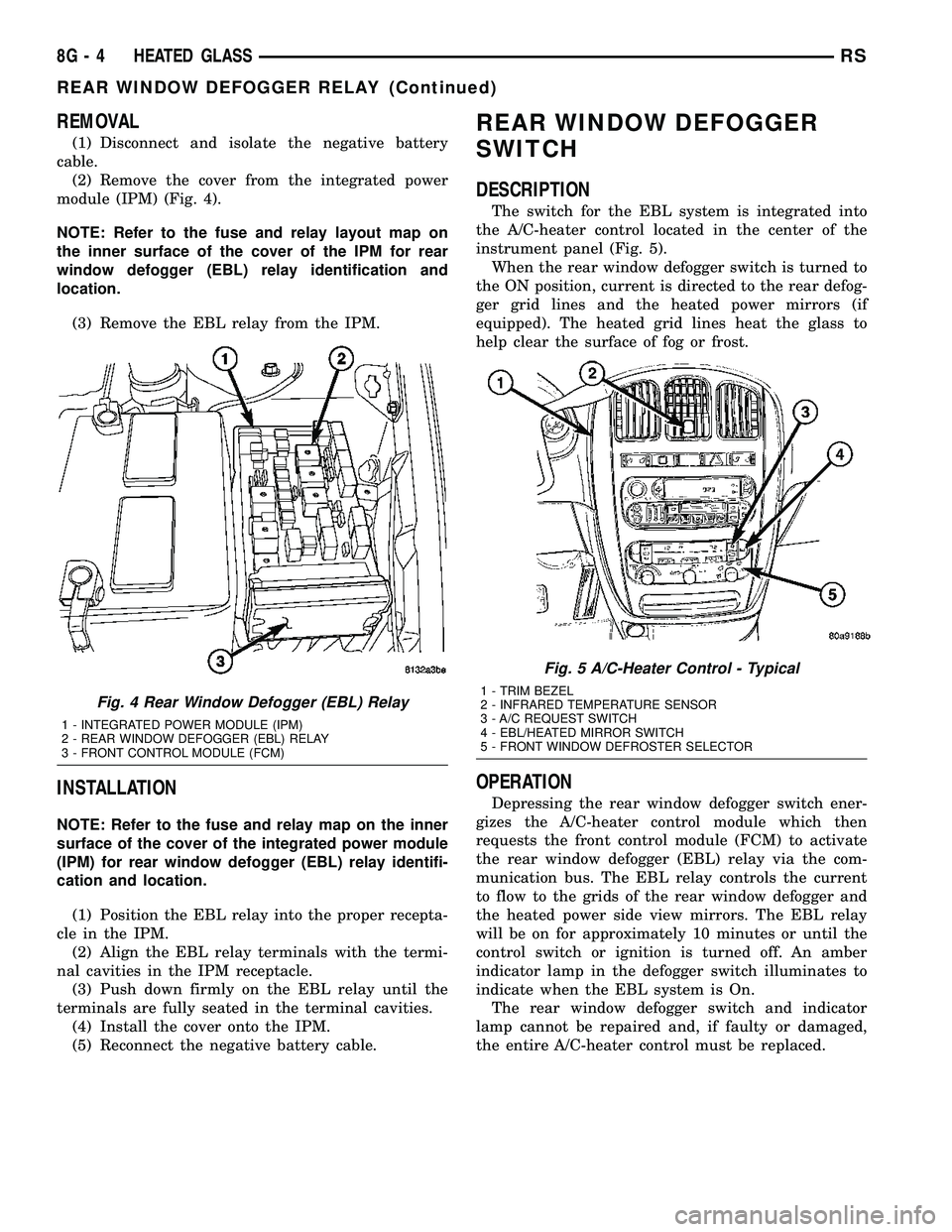
REMOVAL
(1) Disconnect and isolate the negative battery
cable.
(2) Remove the cover from the integrated power
module (IPM) (Fig. 4).
NOTE: Refer to the fuse and relay layout map on
the inner surface of the cover of the IPM for rear
window defogger (EBL) relay identification and
location.
(3) Remove the EBL relay from the IPM.
INSTALLATION
NOTE: Refer to the fuse and relay map on the inner
surface of the cover of the integrated power module
(IPM) for rear window defogger (EBL) relay identifi-
cation and location.
(1) Position the EBL relay into the proper recepta-
cle in the IPM.
(2) Align the EBL relay terminals with the termi-
nal cavities in the IPM receptacle.
(3) Push down firmly on the EBL relay until the
terminals are fully seated in the terminal cavities.
(4) Install the cover onto the IPM.
(5) Reconnect the negative battery cable.
REAR WINDOW DEFOGGER
SWITCH
DESCRIPTION
The switch for the EBL system is integrated into
the A/C-heater control located in the center of the
instrument panel (Fig. 5).
When the rear window defogger switch is turned to
the ON position, current is directed to the rear defog-
ger grid lines and the heated power mirrors (if
equipped). The heated grid lines heat the glass to
help clear the surface of fog or frost.
OPERATION
Depressing the rear window defogger switch ener-
gizes the A/C-heater control module which then
requests the front control module (FCM) to activate
the rear window defogger (EBL) relay via the com-
munication bus. The EBL relay controls the current
to flow to the grids of the rear window defogger and
the heated power side view mirrors. The EBL relay
will be on for approximately 10 minutes or until the
control switch or ignition is turned off. An amber
indicator lamp in the defogger switch illuminates to
indicate when the EBL system is On.
The rear window defogger switch and indicator
lamp cannot be repaired and, if faulty or damaged,
the entire A/C-heater control must be replaced.
Fig. 4 Rear Window Defogger (EBL) Relay
1 - INTEGRATED POWER MODULE (IPM)
2 - REAR WINDOW DEFOGGER (EBL) RELAY
3 - FRONT CONTROL MODULE (FCM)
Fig. 5 A/C-Heater Control - Typical
1 - TRIM BEZEL
2 - INFRARED TEMPERATURE SENSOR
3 - A/C REQUEST SWITCH
4 - EBL/HEATED MIRROR SWITCH
5 - FRONT WINDOW DEFROSTER SELECTOR
8G - 4 HEATED GLASSRS
REAR WINDOW DEFOGGER RELAY (Continued)
Page 350 of 2339

REAR WINDOW DEFOGGER
GRID
STANDARD PROCEDURE
GRID REPAIR PROCEDURE
WARNING: Materials contained in the Repair Kit
(Part Number 04549275) may cause skin or eye irri-
tation. The kit contains epoxy resin and amine type
hardener, which are harmful if swallowed. Avoid
contact with the skin and eyes. For skin contact,
wash the affected areas with soap and water. For
contact with the eyes, flush with plenty of water. Do
not take internally. If taken internally, induce vomit-
ing and call a physician immediately. Use with ade-
quate ventilation. Do not use near fire or flame.
Contains flammable solvents. Keep out of the reach
of children. Failure to follow the warnings could
result in possible personal injury or death.
Repair of the rear glass heating grid lines, bus
bars or terminals can be accomplished using the
MopartRear Window Defogger Repair Kit (Part
Number 04549275) or equivalent.
(1) Mask the repair area with masking tape so
that the conductive epoxy can be applied neatly (Fig.
6). Extend the epoxy application onto the grid line or
the bus bar on each side of the break.
(2) Follow the instructions in the repair kit for
preparing the damaged area.
(3) Remove the package separator clamp and mix
the two conductive epoxy components thoroughly
within the packaging. Fold the package in half and
cut the center corner to dispense the epoxy.
(4) For grid line repairs, mask the area to be
repaired with masking tape or use a template.
(5) Apply the epoxy through the slit in the mask-
ing tape or template. Overlap both ends of the break
by at least 19 millimeters (0.75 inch).
(6) For a terminal replacement, mask the adjacent
areas so the epoxy can be extended onto the adjacent
grid line as well as the bus bar. Apply a thin layer of
epoxy to the area where the terminal was fastened
and onto the adjacent grid line.(7) Apply a thin layer of conductive epoxy to the
terminal and place it in the proper location on the
bus bar. To prevent the terminal from moving while
the epoxy is curing, it must be wedged or clamped.
(8) Carefully remove the masking tape or tem-
plate.
CAUTION: Do not allow the glass surface to exceed
204É C (400É F) when using a heat gun, or the glass
may fracture.
(9) Allow the epoxy to cure 24 hours at room tem-
perature, or carefully use a heat gun for fifteen min-
utes. When using a heat gun, hold it approximately
25.4 centimeters (10 inches) from the repair and do
not allow the glass surface to exceed 204É C (400É F).
NOTE: Do not attach the wire harness connectors
to the terminals until the curing process is com-
plete.
(10) After the conductive epoxy is properly cured,
remove the wedge or clamp from the terminal.
(11) Connect the wire harness leads to the grid
terminals and verify EBL operation.
Fig. 6 Grid Line Repair
1 - BREAK
2 - GRID LINE
3 - MASKING TAPE
RSHEATED GLASS8G-5