tow CHRYSLER VOYAGER 2005 Workshop Manual
[x] Cancel search | Manufacturer: CHRYSLER, Model Year: 2005, Model line: VOYAGER, Model: CHRYSLER VOYAGER 2005Pages: 2339, PDF Size: 59.69 MB
Page 514 of 2339

ger side front seat cushion unit with another com-
plete service replacement package. (Refer to 23 -
BODY/SEATS/SEAT CUSHION - FRONT -
REMOVAL).
WARNING: Never replace both the Occupant
Restraint Controller (ORC) and the Occupant Clas-
sification Module (OCM) at the same time. If both
require replacement, replace one, then perform the
Airbag System test (Refer to 8 - ELECTRICAL/RE-
STRAINTS - DIAGNOSIS AND TESTING - AIRBAG
SYSTEM) before replacing the other. Both the ORC
and the OCM store Occupant Classification System
(OCS) calibration data, which they transfer to one
another when one of them is replaced. If both are
replaced at the same time, an irreversible fault will
be set in both modules and the OCS may malfunc-
tion may result in personal injury or death.
(1) Carefully position the Occupant Classification
Module (OCM) to the OCM bracket (Fig. 36). When
the OCM is correctly positioned, the connector on the
module will be pointed to right side of the vehicle.
(2) Install the two screws to the OCM. Torque the
screws to 2 N´m (20 in. lbs.).
(3) Connect the seat wire harness connector for the
OCM. Be certain that the latches on the connector
are each fully engaged.(4) Install the lock pin into the connector lock
tower on the OCM.
WARNING: Do not connect the battery negative
cable (Refer to 8 - ELECTRICAL/RESTRAINTS -
DIAGNOSIS AND TESTING - AIRBAG SYSTEM). Per-
sonal injury or death may result if the system test
is not performed first.
WARNING: Following successful completion of the
Airbag System test procedure, the Occupant Classi-
fication System Verification Test must be done
using a scan tool and the appropriate diagnostic
information.
(5) Verify vehicle and system operation.
(6) Close hood.
OCCUPANT RESTRAINT
CONTROLLER
DESCRIPTION
The Occupant Restraint Controller (ORC) (Fig. 37)
is also sometimes referred to as the Airbag Control
Module (ACM).
Fig. 36 OCM - REMOVE/INSTALL
1 - OCCUPANT CLASSIFICATION MODULE (OCM)
2 - LOCK TOWER
3 - LOCK PIN
4 - CONNECTOR
5 - SCREW (2)
6 - BRACKET
Fig. 37 OCCUPANT RESTRAINT CONTROLLER -
TYPICAL
1 - ORC
2 - ORIENTATION ARROW UPON INSTALLATION
3 - LABEL
4 - ORC ELECTRICAL CONNECTORS
RSRESTRAINTS8O-27
OCCUPANT CLASSIFICATION MODULE (Continued)
Page 515 of 2339
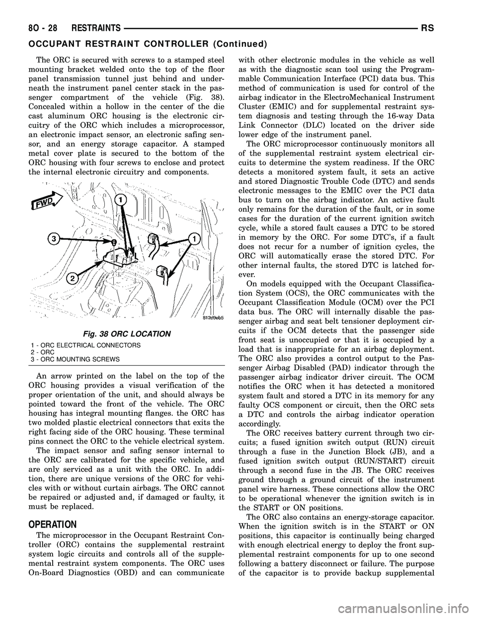
The ORC is secured with screws to a stamped steel
mounting bracket welded onto the top of the floor
panel transmission tunnel just behind and under-
neath the instrument panel center stack in the pas-
senger compartment of the vehicle (Fig. 38).
Concealed within a hollow in the center of the die
cast aluminum ORC housing is the electronic cir-
cuitry of the ORC which includes a microprocessor,
an electronic impact sensor, an electronic safing sen-
sor, and an energy storage capacitor. A stamped
metal cover plate is secured to the bottom of the
ORC housing with four screws to enclose and protect
the internal electronic circuitry and components.
An arrow printed on the label on the top of the
ORC housing provides a visual verification of the
proper orientation of the unit, and should always be
pointed toward the front of the vehicle. The ORC
housing has integral mounting flanges. the ORC has
two molded plastic electrical connectors that exits the
right facing side of the ORC housing. These terminal
pins connect the ORC to the vehicle electrical system.
The impact sensor and safing sensor internal to
the ORC are calibrated for the specific vehicle, and
are only serviced as a unit with the ORC. In addi-
tion, there are unique versions of the ORC for vehi-
cles with or without curtain airbags. The ORC cannot
be repaired or adjusted and, if damaged or faulty, it
must be replaced.
OPERATION
The microprocessor in the Occupant Restraint Con-
troller (ORC) contains the supplemental restraint
system logic circuits and controls all of the supple-
mental restraint system components. The ORC uses
On-Board Diagnostics (OBD) and can communicatewith other electronic modules in the vehicle as well
as with the diagnostic scan tool using the Program-
mable Communication Interface (PCI) data bus. This
method of communication is used for control of the
airbag indicator in the ElectroMechanical Instrument
Cluster (EMIC) and for supplemental restraint sys-
tem diagnosis and testing through the 16-way Data
Link Connector (DLC) located on the driver side
lower edge of the instrument panel.
The ORC microprocessor continuously monitors all
of the supplemental restraint system electrical cir-
cuits to determine the system readiness. If the ORC
detects a monitored system fault, it sets an active
and stored Diagnostic Trouble Code (DTC) and sends
electronic messages to the EMIC over the PCI data
bus to turn on the airbag indicator. An active fault
only remains for the duration of the fault, or in some
cases for the duration of the current ignition switch
cycle, while a stored fault causes a DTC to be stored
in memory by the ORC. For some DTC's, if a fault
does not recur for a number of ignition cycles, the
ORC will automatically erase the stored DTC. For
other internal faults, the stored DTC is latched for-
ever.
On models equipped with the Occupant Classifica-
tion System (OCS), the ORC communicates with the
Occupant Classification Module (OCM) over the PCI
data bus. The ORC will internally disable the pas-
senger airbag and seat belt tensioner deployment cir-
cuits if the OCM detects that the passenger side
front seat is unoccupied or that it is occupied by a
load that is inappropriate for an airbag deployment.
The ORC also provides a control output to the Pas-
senger Airbag Disabled (PAD) indicator through the
passenger airbag indicator driver circuit. The OCM
notifies the ORC when it has detected a monitored
system fault and stored a DTC in its memory for any
faulty OCS component or circuit, then the ORC sets
a DTC and controls the airbag indicator operation
accordingly.
The ORC receives battery current through two cir-
cuits; a fused ignition switch output (RUN) circuit
through a fuse in the Junction Block (JB), and a
fused ignition switch output (RUN/START) circuit
through a second fuse in the JB. The ORC receives
ground through a ground circuit of the instrument
panel wire harness. These connections allow the ORC
to be operational whenever the ignition switch is in
the START or ON positions.
The ORC also contains an energy-storage capacitor.
When the ignition switch is in the START or ON
positions, this capacitor is continually being charged
with enough electrical energy to deploy the front sup-
plemental restraint components for up to one second
following a battery disconnect or failure. The purpose
of the capacitor is to provide backup supplemental
Fig. 38 ORC LOCATION
1 - ORC ELECTRICAL CONNECTORS
2 - ORC
3 - ORC MOUNTING SCREWS
8O - 28 RESTRAINTSRS
OCCUPANT RESTRAINT CONTROLLER (Continued)
Page 517 of 2339
WARNING: Never replace both the Occupant
Restraint Controller (ORC) and the Occupant Clas-
sification Module (OCM) at the same time. If both
require replacement, replace one, then perform the
Airbag System test (Refer to 8 - ELECTRICAL/RE-
STRAINTS - DIAGNOSIS AND TESTING - AIRBAG
SYSTEM) before replacing the other. Both the ORC
and the OCM store Occupant Classification System
(OCS) calibration data, which they transfer to one
another when one of them is replaced. If both are
replaced at the same time, an irreversible fault will
be set in both modules and the OCS may malfunc-
tion and result in personal injury or death.
(1) Install the ORC into vehicle (Fig. 39).
(2) Connect the wire connector to the ORC (Fig.
39).
(3) Install three bolts holding ORC to floor bracket
(Fig. 39). Torque bolts to 7.3 - 9.6 N´m (65 to 85 in.
lbs.)
(4) Install the storage bin onto the instrument
panel (Refer to 23 - BODY/INSTRUMENT PANEL/
STORAGE BIN - INSTALLATION).
WARNING: Do not connect the battery negative
cable (Refer to 8 - ELECTRICAL/RESTRAINTS -
DIAGNOSIS AND TESTING - AIRBAG SYSTEM). Per-
sonal injury or death may result if the system test
is not performed first.
(5) Verify vehicle and system operation.
(6) Close hood.
PASSENGER AIRBAG
DESCRIPTION
WARNING: Never disassemble the passenger air-
bag. The passenger airbag has no serviceable
parts. If tampered with internally, the airbag could
deploy and result in personal injury or death.
The Passenger Airbag is located beneath the
instrument panel and pad assembly. The airbag is
mounted to the back side of the instrument panel
reinforcement.
The instrument panel top pad is the most visible
part of the passenger airbag system. Located under
the instrument panel top pad are the airbag door, the
passenger airbag cushion and the airbag cushion
supporting components.
The passenger airbag includes a magnesium hous-
ing within which the cushion and inflator are
mounted and sealed.
Following a passenger airbag deployment, the pas-
senger airbag and the instrument panel must bereplaced. The passenger airbag cannot be repaired,
and must be replaced if deployed or damaged in any
way.
OPERATION
The passenger airbag is equipped with two infla-
tors, each with three levels of pressure output. The
inflators seal the hole in the airbag cushion so it can
discharge the gas it produces directly into the cush-
ion when supplied with the proper electrical signal.
Following an airbag deployment, the airbag cushion
quickly deflates by venting this gas through the
cushion material towards the instrument panel.
The passenger airbag is secured with screws to the
instrument panel beneath the instrument panel top
pad and above the glove box opening. The instrument
panel top pad above the glove box opening conceals
the airbag door and a predetermined hinge line
beneath its decorative cover. Upon airbag deploy-
ment, the top pad will bend at the hinge line and the
door will fold back out of the way onto the top of the
instrument panel.
When the front airbag system is deployed, the fol-
lowingMUSTbe replaced:
²Complete Steering Column Assembly.
²Lower Steering Column Coupler.
²Steering Wheel.
²Clock Spring.
²Driver Airbag.
²Passenger Airbag.
²Upper Instrument Panel with Pad.
CARE OF UNDEPLOYED AIRBAGS
Airbags must be stored in their original special
container until used for service. At no time should a
source of electricity be permitted near the inflator on
the back of an airbag. When carrying or handling an
undeployed airbag, the trim side of the airbag should
be pointing away from the body to minimize possibil-
ity of injury if accidental deployment occurs. Do not
place undeployed airbag face down on a solid surface,
the airbag will propel into the air if accidental
deployment occurs.
REMOVAL
DEPLOYED AIRBAG
(1) Open hood.
(2) Disconnect and isolate the battery negative
cable.
(3)
8O - 30 RESTRAINTSRS
OCCUPANT RESTRAINT CONTROLLER (Continued)
Page 518 of 2339

WARNING: Wait two minutes for the airbag system
reserve capacitor to discharge before beginning
any airbag system or component service. Failure to
do so may result in accidental airbag deployment,
personal injury or death.
(4) Clean powder residue from interior of vehicle
(Refer to 8 - ELECTRICAL/RESTRAINTS - STAN-
DARD PROCEDURE - SERVICE AFTER AN AIR-
BAG DEPLOYMENT).
(5) Remove instrument panel (Refer to 23 - BODY/
INSTRUMENT PANEL/INSTRUMENT PANEL
ASSEMBLY - REMOVAL).
(6) Remove all reusable components from the
upper instrument panel and transfer to the new
instrument panel.
UNDEPLOYED AIRBAG
(1) Open hood.
(2) Disconnect and isolate the battery negative
cable.
(3)
WARNING: Wait two minutes for the airbag system
reserve capacitor to discharge before beginning
any airbag system or component service. Failure to
do so may result in accidental airbag deployment,
personal injury or death.
(4) Remove center console bin between front seats.
(5) Remove left front door sill plate using a trim
stick (special tool #C-4755) or equivalent, and gently
prying up on sill plate.
(6) Remove left cowl panel using a trim stick or
equivalent, and gently prying out on cowl panel.
(7) Remove four screws to lower steering column
cover and remove cover.
(8) Unsnap parking brake lever from knee blocker
reinforcement.
(9) Remove Data Link Connector (DLC) from knee
blocker.
(10) Remove screws to knee blocker.
(11) Unsnap left A-pillar lower extension trim
using a trim stick or equivalent.
(12) Remove three left side instrument panel A-pil-
lar retaining bolts and loosen the instrument panel
roll down bolt.
(13) Remove four nuts at brake pedal support
bracket to instrument panel.
(14) Using a trim stick or equivalent, gently pry
off left side upper A-pillar trim.
(15) Remove six screws and two wiring connectors
to lower instrument panel cubby bin at bottom of
center stack.
(16) Remove two left side nuts at instrument panel
center stack support to floor.(17) Remove two right side nuts at instrument
panel center stack support to floor.
(18) Remove right front door sill plate using a trim
stick or equivalent, and gently prying up on sill
plate.
(19) Remove right cowl panel using a trim stick or
equivalent, and gently prying out on cowl panel.
(20) Using a trim stick or equivalent, gently pry
out on right instrument panel end cap.
(21) Unsnap right A-pillar lower extension trim
using a trim stick or equivalent.
(22) Remove three right side instrument panel
A-pillar retaining bolts and loosen the instrument
panel roll down bolt.
(23) Using a trim stick or equivalent, gently pry
off right side upper A-pillar trim.
(24) Open glove box, pinch in sides and roll down
towards floor. With a firm pull, snap glove box door
off hinges and remove.
(25) Using a trim stick or equivalent, gently pry
up on rear of instrument panel top cover and then
pull rearward and out.
(26) Using a trim stick or equivalent, gently pry
off the filler bezel just above the cup holder to expose
the lower screws to center bezel.
(27) Remove two screws and then using a trim
stick or equivalent, gently pry off instrument panel
center bezel.
(28) Remove center bezel wiring connectors to
HVAC control and switch assembly (hazard, rear
wiper/washer, heated seats) and remove bezel.
(29) Slide cup holder assembly from instrument
panel.
(30) Remove nineteen screws to right lower instru-
ment panel trim (glove box surround), unplug glove
box lamp wire connector, and remove panel.
(31) Remove four screws and wiring connectors to
radio and remove radio.
(32) Remove one far left instrument panel speaker
retaining screw.
(33) Remove four screws along top front edge of
instrument panel cover/pad.
(34) Remove seven lower instrument panel cover/
pad retaining screws starting from right of vehicle
and only removing these seven, not all of them.
(35) Remove six upper fence line instrument panel
retaining bolts.
(36) Roll back instrument panel just enough to
increase access to the passenger airbag retaining
bolts at the reinforcement. Lift the instrument panel
up slightly so as not to damage the air distribution to
HVAC unit seal.
(37) Disconnect the passenger airbag electrical
connector. Using a trim stick or equivalent, gently
pry electrical connector off of instrument panel rein-
forcement.
RSRESTRAINTS8O-31
PASSENGER AIRBAG (Continued)
Page 521 of 2339

²The ORC receives an occupant classification
message indicating that the passenger front seat is
empty.
²The seat is occupied by a load equal to or
greater than a fifth percentile female.
²OR, until the ignition switch is turned to the
OFF position, whichever of these three occurs first.
²Load Undetermined Occupant Classifica-
tion Message- Each time the ORC receives a mes-
sage from the OCM indicating that a load cannot be
determined in the passenger front seat, the passen-
ger airbag and seat belt tensioner deployment cir-
cuits are deactivated and the PAD indicator will be
illuminated. The indicator remains illuminated until:
²The ORC receives an occupant classification
message indicating that the passenger front seat is
empty.
²The seat is occupied by a load equal to or
greater than a fifth percentile female.
²OR, until the ignition switch is turned to the
OFF position, whichever of these three occurs first.
²Communication Error- If the ORC receives
invalid occupant classification messages or no mes-
sages from the OCM, the PAD indicator is illumi-
nated. The indicator remains illuminated until:
²The ORC receives an occupant classification
message indicating that the passenger front seat is
empty.
²The seat is occupied by a load equal to or
greater than a fifth percentile female.
²OR, until the ignition switch is turned to the
OFF position, whichever of these three occurs first.
The ORC continually monitors the occupant classi-
fication messages from the OCM to decide whether
the passenger airbag and seat belt tensioner deploy-
ment circuits should be activated or deactivated.
Note that there may be several seconds of delay
between changes in the detected occupant status and
PAD indications. This is a programmed feature of the
OCM used to prevent a flashing indicator condition
resulting from the normal shifting of occupant weight
on the passenger seat cushion. The ORC then pro-
vides the proper control output to turn the PAD indi-
cator ON or OFF.
The ORC will store a Diagnostic Trouble Code
(DTC) for any malfunction it detects. For proper
diagnosis of the OCM, the ORC, the PCI data bus, or
the electronic message inputs to the ORC that con-
trol the PAD indicator, use a scan tool and the appro-
priate diagnostic information.REMOVAL
(1) Open hood.
(2) Disconnect and isolate the battery negative
cable.
(3)
WARNING: Wait two minutes for the airbag system
reserve capacitor to discharge before beginning
any airbag system or component service. Failure to
do so may result in accidental airbag deployment,
personal injury or death.
(4) Remove instrument panel center bezel (Refer to
23 - BODY/INSTRUMENT PANEL/INSTRUMENT
PANEL CENTER BEZEL - REMOVAL).
(5) From the back of the center bezel, depress the
two latches toward the indicator housing and push
the indicator out through the face of the center bezel.
INSTALLATION
(1) From the face of the instrument panel center
bezel, align the Passenger Airbag Disabled (PAD)
indicator housing with the mounting hole.
(2) Firmly push the indicator into the center bezel
until the two latches are fully engaged on the back of
the cap and are snapped in.
(3) Install the instrument panel center bezel (Refer
to 23 - BODY/INSTRUMENT PANEL/INSTRUMENT
PANEL CENTER BEZEL - INSTALLATION).
WARNING: Do not connect the battery negative
cable (Refer to 8 - ELECTRICAL/RESTRAINTS -
DIAGNOSIS AND TESTING - AIRBAG SYSTEM). Per-
sonal injury or death may result if the system test
is not performed first.
WARNING: Following successful completion of the
Airbag System test procedure, the Occupant Classi-
fication System Verification Test must be done
using a scan tool and the appropriate diagnostic
information.
(4) Close hood.
(5) Verify system and vehicle operation.
8O - 34 RESTRAINTSRS
PASSENGER AIRBAG DISABLED INDICATOR (Continued)
Page 543 of 2339
REMOVAL
(1) Disconnect and isolate the battery negative
cable.
(2) Remove the Steering Column Opening Cover
(Refer to 23 - BODY/INSTRUMENT PANEL/STEER-
ING COLUMN OPENING COVER - REMOVAL).
(3) Remove the steering column upper and lower
shrouds (Refer to 19 - STEERING/COLUMN/UPPER
SHROUD - REMOVAL) and (Refer to 19 - STEER-
ING/COLUMN/LOWER SHROUD - REMOVAL).
(4) Disengage the steering column wire harness
from the Sentry Key Remote Entry Module
(SKREEM).
(5) Remove the one screws securing the SKREEM
to the steering column.
(6) Rotate the SKREEM upwards and then to the
side away from the steering column to slide the
SKREEM antenna ring from around the ignition
switch lock cylinder housing.
(7) Remove the SKREEM from the vehicle.
INSTALLATION
(1) Slip the Sentry Key Remote Entry Module
(SKREEM) antenna ring around the ignition switch
lock cylinder housing. Rotate the SKREEM down-
wards and then towards the steering column.
(2) Install the one screws securing the SKREEM to
the steering column.
(3) Connect the steering column wire harness to
the SKREEM.
(4) Install the steering column upper and lower
shrouds (Refer to 19 - STEERING/COLUMN/UPPER
SHROUD - INSTALLATION) and (Refer to 19 -
STEERING/COLUMN/LOWER SHROUD - INSTAL-
LATION).
(5) Install the Steering Column Opening Cover
(Refer to 23 - BODY/INSTRUMENT PANEL/STEER-
ING COLUMN OPENING COVER - INSTALLA-
TION)
(6) Connect the battery negative cable.
TRANSPONDER KEY
DESCRIPTION
The Sentry Key Remote Entry System (SKREES)
uses a transponder chip that is integral to the circuit
board of the integrated ignition key (SKREES and
RKE incorporated) to communicate with the Sentry
Key Remote Entry Module (SKREEM). Ignition keys
are supplied with the vehicle when it is shipped from
the factory.
For export vehicles equipped with SKREES, the
transponder chip is undermolded within the head of
the key.
OPERATION
Each Sentry Key has a unique transponder identi-
fication code permanently programmed into it by the
manufacturer. Likewise, the Sentry Key Remote
Entry Module (SKREEM) has a unique9Secret Key9
code programmed into it by the manufacturer as
well. When a Sentry Key is programmed into the
memory of the SKREEM, the SKREEM stores the
transponder identification code from the Sentry Key,
and the Sentry Key learns the9Secret Key9code from
the SKREEM. Once the Sentry Key learns the
9Secret Key9code of the SKREEM, it is also perma-
nently programmed into the transponder's memory.
Therefore, blank keys for the Sentry Key Remote
Entry System (SKREES) must be programmed by
the SKREEM in addition to being cut to match the
mechanical coding of the ignition lock cylinder. Refer
to Electrical, Vehicle Theft Security, Transponder
Key, Standard Procedure - Transponder Program-
ming.
The Sentry Key's transponder is within the range
of the SKREEM's transceiver antenna ring when it is
inserted into the ignition lock cylinder. When the
ignition switch is turned to the ON position, the
SKREEM communicates with the Sentry Key via a
radio frequency (RF) signal. The SKREEM deter-
mines if a valid key is present based on the informa-
tion it receives from the Sentry Key. If a valid key is
detected, that fact is communicated to the PCM via
the PCI bus and the vehicle is allowed to continue
running. If an invalid key is received by the PCM or
no status at all is communicated, the vehicle will
stall after two (2) seconds of running. The indicator
light will be flashing at this point. The Sentry Key's
transponder can not be repaired. If it is faulty or
damaged, it must be replaced.
Common communication problems:
²Two transponder keys too close together.
²Speed Pass too close to transponder key.
Solid indicator that there is a system failure.
²Loss of PCM communication.
²Failed antenna circuit.
STANDARD PROCEDURE - TRANSPONDER
PROGRAMMING
USING A DRBIIITSCAN TOOL
All Sentry Keys included with the vehicle are pre-
programmed to work with the Sentry Key Remote
Entry System (SKREES) when it is shipped from the
factory. The Sentry Key Remote Entry Module
(SKREEM) can be programmed to recognize up to a
total of eight Sentry Keys. When programming a
blank Sentry Key transponder, the key must first be
cut to match the ignition lock cylinder of the vehicle
for which it will be used. The vehicle's four digit PIN
8Q - 6 VEHICLE THEFT SECURITYRS
SENTRY KEY REMOTE ENTRY MODULE (Continued)
Page 564 of 2339
WIRING
TABLE OF CONTENTS
page page
WIRING DIAGRAM INFORMATION....... 8W-01-1
COMPONENT INDEX.................. 8W-02-1
POWER DISTRIBUTION............... 8W-10-1
GROUND DISTRIBUTION.............. 8W-15-1
BUS COMMUNICATIONS.............. 8W-18-1
CHARGING SYSTEM.................. 8W-20-1
STARTING SYSTEM.................. 8W-21-1
FUEL/IGNITION SYSTEM.............. 8W-30-1
TRANSMISSION CONTROL SYSTEM..... 8W-31-1
VEHICLE SPEED CONTROL............ 8W-33-1
ANTILOCK BRAKES................... 8W-35-1
VEHICLE THEFT SECURITY SYSTEM..... 8W-39-1
INSTRUMENT CLUSTER............... 8W-40-1
HORN/CIGAR LIGHTER/POWER OUTLET . . 8W-41-1
AIR CONDITIONING-HEATER........... 8W-42-1
OCCUPANT RESTRAINT SYSTEM........ 8W-43-1
INTERIOR LIGHTING.................. 8W-44-1
BODY CONTROL MODULE............. 8W-45-1
MESSAGE CENTER................... 8W-46-1
AUDIO SYSTEM..................... 8W-47-1REAR WINDOW DEFOGGER............ 8W-48-1
OVERHEAD CONSOLE................. 8W-49-1
FRONT LIGHTING.................... 8W-50-1
REAR LIGHTING..................... 8W-51-1
TURN SIGNALS...................... 8W-52-1
WIPERS............................ 8W-53-1
TRAILER TOW....................... 8W-54-1
NAVIGATION/TELECOMMUNICATIONS.... 8W-55-1
CONVENIENCE SYSTEMS.............. 8W-56-1
POWER WINDOWS................... 8W-60-1
POWER DOOR LOCKS................ 8W-61-1
POWER MIRRORS................... 8W-62-1
POWER SEATS...................... 8W-63-1
POWER SUNROOF................... 8W-64-1
SPLICE INFORMATION................ 8W-70-1
CONNECTOR PIN-OUTS............... 8W-80-1
CONNECTOR/GROUND/SPLICE
LOCATION........................ 8W-91-1
POWER DISTRIBUTION SYSTEM........ 8W-97-1 RSWIRING
8W-1
Page 571 of 2339
DESCRIPTION - CIRCUIT FUNCTIONS
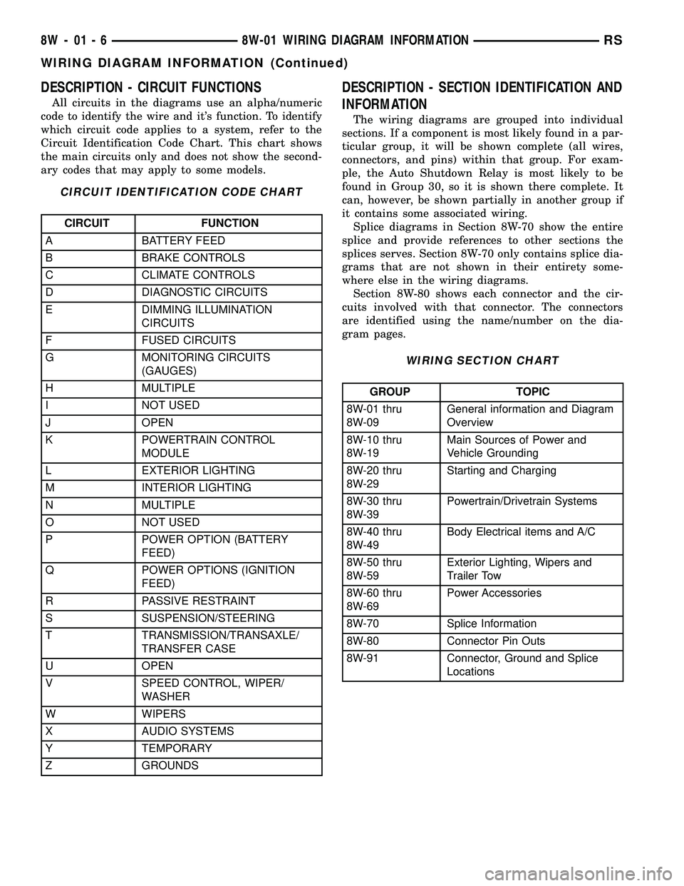
All circuits in the diagrams use an alpha/numeric
code to identify the wire and it's function. To identify
which circuit code applies to a system, refer to the
Circuit Identification Code Chart. This chart shows
the main circuits only and does not show the second-
ary codes that may apply to some models.
CIRCUIT IDENTIFICATION CODE CHART
CIRCUIT FUNCTION
A BATTERY FEED
B BRAKE CONTROLS
C CLIMATE CONTROLS
D DIAGNOSTIC CIRCUITS
E DIMMING ILLUMINATION
CIRCUITS
F FUSED CIRCUITS
G MONITORING CIRCUITS
(GAUGES)
H MULTIPLE
I NOT USED
J OPEN
K POWERTRAIN CONTROL
MODULE
L EXTERIOR LIGHTING
M INTERIOR LIGHTING
N MULTIPLE
O NOT USED
P POWER OPTION (BATTERY
FEED)
Q POWER OPTIONS (IGNITION
FEED)
R PASSIVE RESTRAINT
S SUSPENSION/STEERING
T TRANSMISSION/TRANSAXLE/
TRANSFER CASE
U OPEN
V SPEED CONTROL, WIPER/
WASHER
W WIPERS
X AUDIO SYSTEMS
Y TEMPORARY
Z GROUNDS
DESCRIPTION - SECTION IDENTIFICATION AND
INFORMATION
The wiring diagrams are grouped into individual
sections. If a component is most likely found in a par-
ticular group, it will be shown complete (all wires,
connectors, and pins) within that group. For exam-
ple, the Auto Shutdown Relay is most likely to be
found in Group 30, so it is shown there complete. It
can, however, be shown partially in another group if
it contains some associated wiring.
Splice diagrams in Section 8W-70 show the entire
splice and provide references to other sections the
splices serves. Section 8W-70 only contains splice dia-
grams that are not shown in their entirety some-
where else in the wiring diagrams.
Section 8W-80 shows each connector and the cir-
cuits involved with that connector. The connectors
are identified using the name/number on the dia-
gram pages.
WIRING SECTION CHART
GROUP TOPIC
8W-01 thru
8W-09General information and Diagram
Overview
8W-10 thru
8W-19Main Sources of Power and
Vehicle Grounding
8W-20 thru
8W-29Starting and Charging
8W-30 thru
8W-39Powertrain/Drivetrain Systems
8W-40 thru
8W-49Body Electrical items and A/C
8W-50 thru
8W-59Exterior Lighting, Wipers and
Trailer Tow
8W-60 thru
8W-69Power Accessories
8W-70 Splice Information
8W-80 Connector Pin Outs
8W-91 Connector, Ground and Splice
Locations
8W - 01 - 6 8W-01 WIRING DIAGRAM INFORMATIONRS
WIRING DIAGRAM INFORMATION (Continued)
Page 583 of 2339
Component Page
Ignition Coil......................... 8W-30
Ignition Switch....................... 8W-10
Impact Sensors....................... 8W-43
Inlet Air Temperature Sensor............ 8W-30
Instrument Cluster.................... 8W-40
Instrument Panel Switch
Bank.................. 8W-43, 44, 52, 53, 63
Integrated Power Module............... 8W-10
Knock Sensor........................ 8W-30
Lamp Assemblies...................... 8W-51
License Lamp..................... 8W-51, 61
Lift Pump Motor...................... 8W-30
Lift Pump Relay...................... 8W-30
Liftgate Ajar Switch................ 8W-39, 61
Liftgate Cinch/Release Motor............ 8W-61
Liftgate Flood Lamps.................. 8W-44
Liftgate Pinch Sensors................. 8W-61
Low Beam Lamps..................... 8W-50
Manifold Absolute Pressure Sensor........ 8W-30
Mass Air Flow Sensor.................. 8W-30
Memory Seat/Mirror/Adjustable Pedals
Module...................... 8W-56, 62, 63
Memory Set Switch.................... 8W-63
Message Center.................... 8W-40, 46
Mode Door Actuator................... 8W-42
Multi-Function Switch............ 8W-50, 52, 53
Natural Vacuum Leak Detection Assembly . . 8W-30
Occupant Classification Module.......... 8W-43
Occupant Restraint Controller........... 8W-43
Overhead Console..................... 8W-49
Oxygen Sensors....................... 8W-30
Park Assist Display.................... 8W-56
Park Assist Module.................... 8W-56
Park Assist Sensors.................... 8W-56
Park Lamp Relay..................... 8W-10
Park Lamps.......................... 8W-50
Park/Turn Signal Lamps................ 8W-50
Parking Brake Switch.................. 8W-40
Power Folding Mirror Switch............ 8W-62
Power Liftgate Module................. 8W-61
Power Liftgate Motor.................. 8W-61
Power Mirror Switch................... 8W-62
Power Mirrors........................ 8W-62
Power Outlets........................ 8W-41
Power Seat Circuit Breaker.............. 8W-10
Power Seat Motors.................... 8W-63
Power Seat Position Sensors............. 8W-63
Power Seat Switches................... 8W-63
Power Window Circuit Breaker........... 8W-10
Power Window Motors.................. 8W-60
Power Window Switches................ 8W-60
Powertrain Control Module........... 8W-30, 31
PTCs............................... 8W-10
Radiator Fan Relaies................... 8W-42Component Page
Radiator Fans........................ 8W-42
Radio............................... 8W-47
Reading Lamps....................... 8W-44
Rear A/C-Heater Unit.................. 8W-42
Rear Auto Temp Control Switch.......... 8W-42
Rear Blower Control Switches............ 8W-42
Rear Blower Motor Power Module......... 8W-42
Rear Dome Lamp..................... 8W-44
Rear Intrusion Sensor.................. 8W-39
Rear Mode Motor..................... 8W-42
Rear Temperature Motor................ 8W-42
Rear View Mirror................ 8W-49, 55, 62
Rear Window Defogger Grid............. 8W-48
Rear Wiper Motor..................... 8W-53
Recirculation Door Actuator............. 8W-42
Remote Radio Switches................. 8W-47
Repeater Lamps...................... 8W-52
Seat Belt Switches.................... 8W-43
Seat Belt Tensioners................... 8W-43
Seat Weight Sensor.................... 8W-43
Sentry Key Remote Entry Module......... 8W-39
Siren............................... 8W-39
Sliding Door Control Modules............ 8W-61
Sliding Door Latch Sensing Switches...... 8W-61
Sliding Door Lock Motors............... 8W-61
Sliding Door Motors................... 8W-61
Speakers............................ 8W-47
Speed Control Servo................... 8W-33
Speed Control Switches................. 8W-33
Speed Sensors........................ 8W-31
Splices.............................. 8W-70
Starter Motor........................ 8W-21
Starter Motor Relay................... 8W-21
Sunroof Module....................... 8W-64
Sunroof Switch....................... 8W-64
Thatcham Alarm Indicator.............. 8W-39
Thatcham Alarm Module................ 8W-39
Throttle Position Sensor................ 8W-30
Traction Control Switch................. 8W-35
Trailer Tow Connector.................. 8W-54
Transmission Control Module............ 8W-31
Transmission Control Relay............. 8W-31
Transmission Range Sensor.............. 8W-31
Transmission Solenoid/Pressure Switch
Assembly.......................... 8W-31
Turn Signal Lamps.................... 8W-52
Vehicle Speed Sensor................... 8W-30
Vent Motors.......................... 8W-60
Visor/Vanity Lamps.................... 8W-44
Washer Fluid Level Switch.............. 8W-53
Washer Pump Motor................... 8W-53
Water In Fuel Sensor.................. 8W-30
Wheel Speed Sensors................... 8W-35
Wiper Module........................ 8W-53
8W - 02 - 2 8W-02 COMPONENT INDEXRS
Page 585 of 2339
Component Page
High Note Horn................. 8W-10-17, 35
Horn Relay.................. 8W-10-17, 35, 60
Ignition Coil....................... 8W-10-42
Ignition Switch . . . 8W-10-18, 25, 36, 37, 45, 46, 49,
54, 55, 61
Instrument Cluster............... 8W-10-25, 52
Instrument Panel Switch Bank........ 8W-10-69
Integrated Power Module . 8W-10-3, 4, 5, 13, 15, 16,
17, 18, 19, 20, 21, 22, 23, 24, 25, 26, 27, 28, 29,
30, 31, 32, 35, 36, 37, 38, 39, 40, 41, 42, 43, 44,
45, 47, 48, 49, 50, 52, 53, 54, 55, 56, 57, 58, 59,
60, 61, 62, 63, 64, 65, 66, 67, 68, 69
Left Fog Lamp.................. 8W-10-15, 27
Left Front Park/Turn
Signal Lamp............ 8W-10-15, 28, 57, 66
Left Headlamp..................... 8W-10-58
Left Headlamp Leveling Motor . . . 8W-10-29, 63, 66
Left High Beam Lamp............... 8W-10-59
Left Low Beam Lamp................ 8W-10-59
Left Park Lamp.............. 8W-10-29, 59, 66
Left Power Mirror................... 8W-10-39
Left Rear Lamp Assembly....... 8W-10-28, 29, 66
Left Repeater Lamp................. 8W-10-52
Left Sliding Door Control Module.... 8W-10-26, 53
Left Turn Signal Lamp............... 8W-10-57
License Lamp................ 8W-10-28, 29, 66
Lift Pump Motor................. 8W-10-23, 43
Lift Pump Relay................. 8W-10-23, 43
Mass Air Flow Sensor................ 8W-10-44
Memory Seat/Mirror/Adjustable Pedals
Module......................... 8W-10-50
Message Center.................... 8W-10-52
Occupant Classification Module........ 8W-10-69
Occupant Restraint Controller...... 8W-10-64, 69
Overhead Console................... 8W-10-40
Park Assist Module............... 8W-10-45, 54
Park Lamp Relay.......... 8W-10-15, 28, 29, 60
Passenger Airbag On/Off Indicator
Lamp.......................... 8W-10-69
Passenger Folding Mirror
Relay.................. 8W-10-22, 24, 45, 48
Passenger Heated Seat Module........ 8W-10-51
Passenger Power Seat Switch.......... 8W-10-51
Passenger Power Window Switch....... 8W-10-31
Power Liftgate Module............ 8W-10-26, 53
Power Mirror Switch........ 8W-10-22, 24, 47, 48
Power Outlet...................... 8W-10-35
Power Seat Circuit Breaker........ 8W-10-25, 50Component Page
Power Window Circuit Breaker...... 8W-10-16, 31
Power Window Switch............... 8W-10-33
Powertrain Control Module . . 8W-10-18, 21, 22, 36,
41, 42, 45, 56, 62, 63, 68
PTC4 ......................... 8W-10-20, 39
PTC7 ................... 8W-10-16, 17, 18, 35
Radiator Fan Relay............ 8W-10-26, 52, 56
Radiator Fan Relay No. 1.......... 8W-10-13, 44
Radiator Fan Relay No. 2....... 8W-10-26, 44, 52
Radiator Fan Relay No. 3............. 8W-10-44
Radio......................... 8W-10-32, 40
Rear A/C-Heater Unit............. 8W-10-19, 38
Rear Blower Motor Power Module . . . 8W-10-19, 38
Rear Blower Motor Relay.... 8W-10-19, 20, 38, 64
Rear Power Outlet............ 8W-10-16, 31, 32
Rear Window Defogger Grid........ 8W-10-20, 39
Rear Wiper Motor................ 8W-10-16, 31
Right Fog Lamp................. 8W-10-15, 27
Right Front Park/Turn
Signal Lamp............ 8W-10-15, 28, 57, 61
Right Headlamp.................... 8W-10-58
Right Headlamp Leveling Motor . . 8W-10-29, 61, 63
Right High Beam Lamp.............. 8W-10-59
Right Low Beam Lamp............... 8W-10-59
Right Park Lamp............. 8W-10-29, 59, 61
Right Power Mirror................. 8W-10-39
Right Rear Lamp
Assembly............ 8W-10-15, 28, 29, 61, 67
Right Repeater Lamp................ 8W-10-52
Right Sliding Door Control Module . . . 8W-10-26, 53
Right Turn Signal Lamp.............. 8W-10-57
Sentry Key Remote Entry
Module.............. 8W-10-40, 46, 49, 54, 55
Siren............................. 8W-10-40
Starter Motor.......... 8W-10-13, 14, 18, 36, 37
Starter Motor Relay...... 8W-10-18, 36, 37, 54, 55
Sunroof Module.................. 8W-10-31, 53
Thatcham Alarm Module . . 8W-10-40, 46, 49, 55, 68
Trailer Tow Connector............ 8W-10-28, 66
Transmission Control Module....... 8W-10-13, 62
Transmission Control Relay..... 8W-10-13, 21, 41
Transmission Solenoid/Pressure Switch
Assembly....................... 8W-10-41
Vehicle Speed Sensor................ 8W-10-43
Washer Fluid Level Switch............ 8W-10-61
Washer Pump Motor................. 8W-10-69
Wiper Module................ 8W-10-16, 30, 60
8W - 10 - 2 8W-10 POWER DISTRIBUTIONRS