Module CHRYSLER VOYAGER 2005 Repair Manual
[x] Cancel search | Manufacturer: CHRYSLER, Model Year: 2005, Model line: VOYAGER, Model: CHRYSLER VOYAGER 2005Pages: 2339, PDF Size: 59.69 MB
Page 348 of 2339
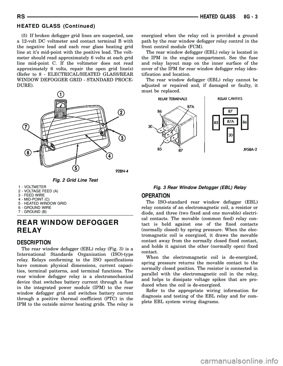
(5) If broken defogger grid lines are suspected, use
a 12-volt DC voltmeter and contact terminal B with
the negative lead and each rear glass heating grid
line at it's mid-point with the positive lead. The volt-
meter should read approximately 6 volts at each grid
line mid-point C. If the voltmeter does not read
approximately 6 volts, repair the open grid line(s)
(Refer to 8 - ELECTRICAL/HEATED GLASS/REAR
WINDOW DEFOGGER GRID - STANDARD PROCE-
DURE).
REAR WINDOW DEFOGGER
RELAY
DESCRIPTION
The rear window defogger (EBL) relay (Fig. 3) is a
International Standards Organization (ISO)-type
relay. Relays conforming to the ISO specifications
have common physical dimensions, current capaci-
ties, terminal patterns, and terminal functions. The
rear window defogger relay is a electromechanical
device that switches battery current through a fuse
in the integrated power module (IPM) to the rear
window defogger grid and switches battery current
through a positive thermal coefficient (PTC) in the
IPM to the outside mirror heating grids. The relay isenergized when the relay coil is provided a ground
path by the rear window defogger relay control in the
front control module (FCM).
The rear window defogger (EBL) relay is located in
the IPM in the engine compartment. See the fuse
and relay layout map on the inner surface of the
cover of the IPM for rear window defogger relay iden-
tification and location.
The rear window defogger (EBL) relay cannot be
adjusted or repaired and, if damaged or faulty, it
must be replaced.
OPERATION
The ISO-standard rear window defogger (EBL)
relay consists of an electromagnetic coil, a resistor or
diode, and three (two fixed and one movable) electri-
cal contacts. The movable (common feed) relay con-
tact is held against one of the fixed contacts
(normally closed) by spring pressure. When the elec-
tromagnetic coil is energized, it draws the movable
contact away from the normally closed fixed contact,
and holds it against the other (normally open) fixed
contact.
When the electromagnetic coil is de-energized,
spring pressure returns the movable contact to the
normally closed position. The resistor is connected in
parallel with the electromagnetic coil in the relay,
and helps to dissipate voltage spikes that are pro-
duced when the coil is de-energized.
Refer to the appropriate wiring information for
diagnosis and testing of the EBL relay and for com-
plete EBL system wiring diagrams.
Fig. 2 Grid Line Test
1 - VOLTMETER
2 - VOLTAGE FEED (A)
3 - FEED WIRE
4 - MID-POINT (C)
5 - HEATED WINDOW GRID
6 - GROUND WIRE
7 - GROUND (B)Fig. 3 Rear Window Defogger (EBL) Relay
RSHEATED GLASS8G-3
HEATED GLASS (Continued)
Page 349 of 2339
REMOVAL
(1) Disconnect and isolate the negative battery
cable.
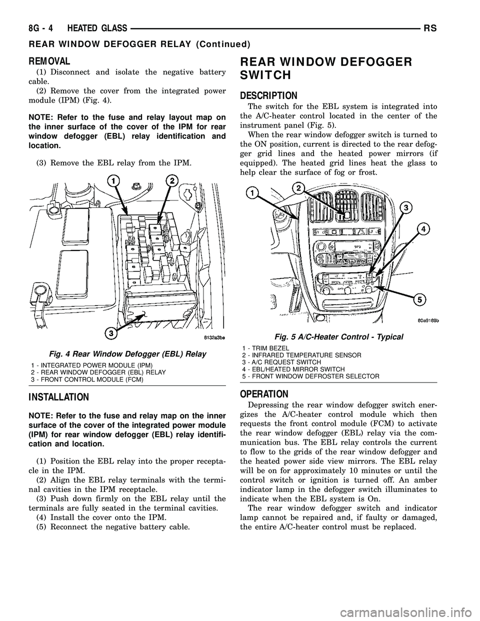
(2) Remove the cover from the integrated power
module (IPM) (Fig. 4).
NOTE: Refer to the fuse and relay layout map on
the inner surface of the cover of the IPM for rear
window defogger (EBL) relay identification and
location.
(3) Remove the EBL relay from the IPM.
INSTALLATION
NOTE: Refer to the fuse and relay map on the inner
surface of the cover of the integrated power module
(IPM) for rear window defogger (EBL) relay identifi-
cation and location.
(1) Position the EBL relay into the proper recepta-
cle in the IPM.
(2) Align the EBL relay terminals with the termi-
nal cavities in the IPM receptacle.
(3) Push down firmly on the EBL relay until the
terminals are fully seated in the terminal cavities.
(4) Install the cover onto the IPM.
(5) Reconnect the negative battery cable.
REAR WINDOW DEFOGGER
SWITCH
DESCRIPTION
The switch for the EBL system is integrated into
the A/C-heater control located in the center of the
instrument panel (Fig. 5).
When the rear window defogger switch is turned to
the ON position, current is directed to the rear defog-
ger grid lines and the heated power mirrors (if
equipped). The heated grid lines heat the glass to
help clear the surface of fog or frost.
OPERATION
Depressing the rear window defogger switch ener-
gizes the A/C-heater control module which then
requests the front control module (FCM) to activate
the rear window defogger (EBL) relay via the com-
munication bus. The EBL relay controls the current
to flow to the grids of the rear window defogger and
the heated power side view mirrors. The EBL relay
will be on for approximately 10 minutes or until the
control switch or ignition is turned off. An amber
indicator lamp in the defogger switch illuminates to
indicate when the EBL system is On.
The rear window defogger switch and indicator
lamp cannot be repaired and, if faulty or damaged,
the entire A/C-heater control must be replaced.
Fig. 4 Rear Window Defogger (EBL) Relay
1 - INTEGRATED POWER MODULE (IPM)
2 - REAR WINDOW DEFOGGER (EBL) RELAY
3 - FRONT CONTROL MODULE (FCM)
Fig. 5 A/C-Heater Control - Typical
1 - TRIM BEZEL
2 - INFRARED TEMPERATURE SENSOR
3 - A/C REQUEST SWITCH
4 - EBL/HEATED MIRROR SWITCH
5 - FRONT WINDOW DEFROSTER SELECTOR
8G - 4 HEATED GLASSRS
REAR WINDOW DEFOGGER RELAY (Continued)
Page 352 of 2339
HEATED SEAT SYSTEM
TABLE OF CONTENTS
page page
HEATED SEAT SYSTEM
DESCRIPTION..........................7
OPERATION............................8
DIAGNOSIS AND TESTING
HEATED SEAT SYSTEM.................8
HEATED SEAT SWITCH
DESCRIPTION..........................8
OPERATION............................9
DIAGNOSIS AND TESTING
DRIVER HEATED SEAT SWITCH..........9
REMOVAL.............................10
INSTALLATION.........................10HEATED SEAT ELEMENTS
DESCRIPTION.........................11
OPERATION...........................11
DIAGNOSIS AND TESTING
HEATED SEAT ELEMENTS..............11
REMOVAL.............................12
INSTALLATION.........................12
HEATED SEAT SENSOR
DESCRIPTION.........................13
OPERATION...........................13
DIAGNOSIS AND TESTING
HEATED SEAT SENSOR................13
HEATED SEAT SYSTEM
DESCRIPTION
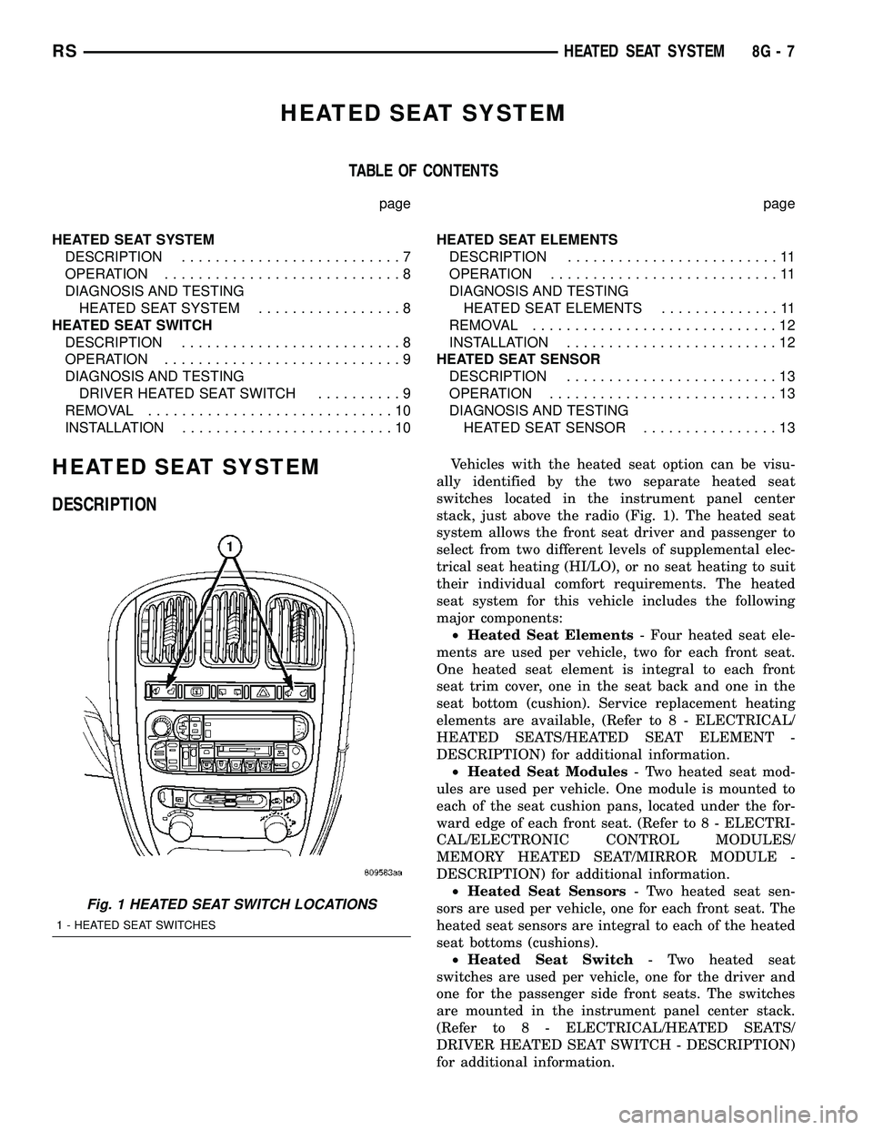
Vehicles with the heated seat option can be visu-
ally identified by the two separate heated seat
switches located in the instrument panel center
stack, just above the radio (Fig. 1). The heated seat
system allows the front seat driver and passenger to
select from two different levels of supplemental elec-
trical seat heating (HI/LO), or no seat heating to suit
their individual comfort requirements. The heated
seat system for this vehicle includes the following
major components:
²Heated Seat Elements- Four heated seat ele-
ments are used per vehicle, two for each front seat.
One heated seat element is integral to each front
seat trim cover, one in the seat back and one in the
seat bottom (cushion). Service replacement heating
elements are available, (Refer to 8 - ELECTRICAL/
HEATED SEATS/HEATED SEAT ELEMENT -
DESCRIPTION) for additional information.
²Heated Seat Modules- Two heated seat mod-
ules are used per vehicle. One module is mounted to
each of the seat cushion pans, located under the for-
ward edge of each front seat. (Refer to 8 - ELECTRI-
CAL/ELECTRONIC CONTROL MODULES/
MEMORY HEATED SEAT/MIRROR MODULE -
DESCRIPTION) for additional information.
²Heated Seat Sensors- Two heated seat sen-
sors are used per vehicle, one for each front seat. The
heated seat sensors are integral to each of the heated
seat bottoms (cushions).
²Heated Seat Switch- Two heated seat
switches are used per vehicle, one for the driver and
one for the passenger side front seats. The switches
are mounted in the instrument panel center stack.
(Refer to 8 - ELECTRICAL/HEATED SEATS/
DRIVER HEATED SEAT SWITCH - DESCRIPTION)
for additional information.
Fig. 1 HEATED SEAT SWITCH LOCATIONS
1 - HEATED SEAT SWITCHES
RSHEATED SEAT SYSTEM8G-7
Page 353 of 2339

Hard wired circuitry connects the heated seat sys-
tem components to each other through the electrical
system of the vehicle. These circuits may be con-
nected to each other, to the vehicle electrical system
and to the heated seat system components through
the use of a combination of soldered splices and
splice block connectors. Refer to the appropriate wir-
ing information for complete circuit schematic or con-
nector pin-out information.
OPERATION
The heated seat system components operate on
battery current received through a fuse in the Inte-
grated Power Module (IPM) on a fused ignition
switch output (run) circuit from the Body Control
Module (BCM). The system will only operate when
the ignition switch is in the On position. The heated
seat system will be turned Off automatically when-
ever the ignition switch is turned to any position
except On. Also, the heated seat system will not oper-
ate when the surface temperature of the seat cushion
cover at either heated seat sensor is above the
designed temperature set points of the system.
DIAGNOSIS AND TESTING
HEATED SEAT SYSTEM
The most efficient means of diagnosing the heated
seat system is by individual component. For diagno-
sis of a specific component refer to the following:
²Heated seat module, (Refer to 8 - ELECTRICAL/
ELECTRONIC CONTROL MODULES/MEMORY
HEATED SEAT/MIRROR MODULE - DIAGNOSIS
AND TESTING).
²Heated seat elements, (Refer to 8 - ELECTRI-
CAL/HEATED SEATS/HEATED SEAT ELEMENT -
DIAGNOSIS AND TESTING).
²Heated seat switch, (Refer to 8 - ELECTRICAL/
HEATED SEATS/DRIVER HEATED SEAT SWITCH
- DIAGNOSIS AND TESTING).
²Heated seat sensor, (Refer to 8 - ELECTRICAL/
HEATED SEATS/HEATED SEAT SENSOR - DIAG-
NOSIS AND TESTING).
Refer to the appropriate wiring information for
complete circuit schematic or connector pin-out infor-
mation.
HEATED SEAT SWITCH
DESCRIPTION
The heated seat switches are mounted in the
instrument panel center bezel (Fig. 2). The two three-
position rocker-type switches, one switch for each
front seat, are incorporated into one large switch
assembly that also includes the hazard, rear window
wiper and washer switches. Each heated seat switch
provides a resistor multiplexed signal to its respec-
tive Heated Seat Module (HSM) through separate
hard wired circuits. Each switch has an Off, Low,
and High position so that both the driver and the
front seat passenger can select a preferred seat heat-
ing mode. Each switch has two Light-Emitting
Diodes (LED) which light to indicate that the heater
for the seat is turned on.
The heated seat switches and their LEDs cannot
be repaired. If either switch or LED is faulty or dam-
aged, the entire switch assembly must be replaced.
Fig. 2 HEATED SEAT SWITCH LOCATION
1 - HEATED SEAT SWITCHES
8G - 8 HEATED SEAT SYSTEMRS
HEATED SEAT SYSTEM (Continued)
Page 354 of 2339
OPERATION
There are three positions that can be selected with
each of the heated seat switches: Off, Low, or High.
When the left side of the switch rocker is fully
depressed, the Low position is selected and the low
position LED indicator illuminates. When the right
side of the switch rocker is fully depressed, the High
position is selected and the high position LED indi-
cator illuminates. When the switch rocker is moved
to its neutral position (middle), Off is selected and
both LED indicators are extinguished.
Each switch provides separate resistor, hard wire
inputs to its respective Heated Seat Module (HSM) to
indicate the selected switch position. The heated seat
module responds to the heated seat switch status
messages by controlling the output to the seat heater
elements of the selected seat. The Low heat position
set point is about 36É C (97É F), and the High heat
position set point is about 41É C (105É F).
DIAGNOSIS AND TESTING
DRIVER HEATED SEAT SWITCH
Refer to the appropriate wiring information for
complete circuit schematic or connector pin-out infor-
mation.
WARNING: REFER TO THE RESTRAINTS SECTION
OF THIS MANUAL BEFORE ATTEMPTING ANY
STEERING WHEEL, STEERING COLUMN, SEAT OR
INSTRUMENT PANEL COMPONENT DIAGNOSIS OR
SERVICE. FAILURE TO TAKE THE PROPER PRE-
CAUTIONS COULD RESULT IN ACCIDENTAL AIR-
BAG DEPLOYMENT AND POSSIBLE PERSONAL
INJURY.
CHECKING SWITCH SIGNAL AND WIRING AT THE
MODULE
(1) Disconnect and isolate the battery negative
cable.
(2) Access and disconnect the gray 4-way connector
from the heated seat module. Visually inspect wiring
terminals for damage that would prevent positive
connection. If not OK, repair or replace the necessary
components.(3) Connect the battery negative cable. Place the
heated seat switch in the LO position. Using an
Ohmmeter, check the resistance between cavities 2
and 3 of the gray connector noted above. Resistance
should be about 3.5 kilohms (3500 ohms). If not OK,
check resistance directly at switch, as noted below. If
OK, proceed to the next step. If not OK, replace the
faulty switch.
(4) Place the heated seat switch in the HI position.
Using an ohmmeter, check the resistance between
cavities 2 and 3 of the gray connector noted above.
Resistance should be about 1.4 kilohms (1400 ohms).
If not OK, check resistance directly at the switch, as
indicated in the Heated Seat Switch Test Table. If
OK, proceed. If not OK replace the faulty switch.
(5) With the system ON in the HI position, check
for battery voltage and ground at cavities 4 and 1. If
OK, proceed with testing remaining components. If
not OK, repair open or shorted wiring.
CHECKING SWITCH ONLY
(1) Disconnect and isolate the battery negative
cable. Remove the center bezel from the instrument
panel (Refer to 23 - BODY/INSTRUMENT PANEL/
INSTRUMENT PANEL CENTER BEZEL -
REMOVAL). Check for continuity between the
ground circuit cavity (#10) of the instrument panel
center bezel switch electrical connector and a good
ground. There should be continuity. If OK, go to Step
2. If not OK, repair the open ground circuit to ground
as required.
(2) Connect the battery negative cable. Turn the
ignition switch to the On position. Check for battery
voltage at the fused ignition switch output (run) cir-
cuit cavity of the instrument panel center bezel
switch electrical connector (#4). If OK, turn the igni-
tion switch to the Off position, and go to Step 3. If
not OK, repair the open fused ignition switch output
(run) circuit as required.
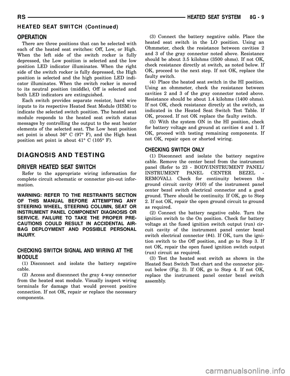
(3) Test the heated seat switch as shown in the
Heated Seat Switch Test chart and the connector pin-
out below (Fig. 3). If OK, go to Step 4. If not OK,
replace the instrument panel center bezel switch
assembly.
RSHEATED SEAT SYSTEM8G-9
HEATED SEAT SWITCH (Continued)
Page 356 of 2339
(3) Install the center bezel onto the instrument
panel, (Refer to 23 - BODY/INSTRUMENT PANEL/
INSTRUMENT PANEL CENTER BEZEL - INSTAL-
LATION).
(4) Connect the battery negative cable.
HEATED SEAT ELEMENTS
DESCRIPTION
The heated seat system includes two seat heating
elements in each front seat, one for the seat cushion
and the other for the seat back. The two elements for
each seat that are connected in series with the
Heated Seat Module (HSM). The temperature sensor
is a Negative Temperature Coefficient (NTC) ther-
mistor. One temperature sensor is used for each seat,
and it is located on the seat cushion heating element
for all models.
The seat heating elements are attached to the seat
cushion cover trim and seat back cover trim units.
The heated seat elements and the temperature sen-
sor cannot be adjusted or repaired and, if faulty or
damaged, the seat element assembly must be
replaced, (Refer to 8 - ELECTRICAL/HEATED
SEATS/HEATED SEAT ELEMENT - REMOVAL).
OPERATION
The heated seat elements resist the flow of electri-
cal current. When battery current is passed through
the elements, the resistance of the elements to the
current flow is released in the form of heat. The tem-
perature sensor is a Negative Temperature Coeffi-
cient (NTC) thermistor. When the temperature of the
seat cushion cover rises, the resistance of the sensor
decreases. The heated seat module supplies a five-
volt signal to one side of each sensor, and monitors
the voltage drop through the sensor on a return cir-
cuit. The heated seat module uses this temperature
sensor input to monitor the temperature of the seat,
and regulates the current flow to the seat heating
elements accordingly.
DIAGNOSIS AND TESTING
HEATED SEAT ELEMENTS
The wire harness connectors for the seat cushion
and seat back heating elements are located under the
seat, at the heated seat module. Refer to the appro-
priate wiring information for complete circuit sche-
matic or connector pin-out information.
In order to access and test the heated seat ele-
ments it will be necessary to remove the appropriate
front seat retaining bolts and lay the seat rearward,
up against one of the rear seats. It is not necessary
to disconnect the seat electrical connectors, just use
care not to damage the attached wire harnesses
while testing.
NOTE: When checking heated seat elements for
continuity, be certain to move the heating element
being checked. Moving the element, such as sitting
in the seat will eliminate the possibility of an inter-
mittent open in the element which would only be
evident if the element was in a certain position.
Failure to check the element in various positions
could result in an incomplete test.
SEAT CUSHION ELEMENT
(1) From under the vehicle, remove the appropri-
ate seats four retaining nuts.
(2) From inside the vehicle, pull the seat up, off
the mounting studs and lay it back, up against one of
the rear seats.
(3) Locate the heated seat module, attached to the
bottom of the seat cushion pan. Remove the heated
seat module from the seat cushion pan. Do not dis-
connect the electrical connectors at this time.
(4) Locate and disconnect the green 4-way electri-
cal connector, connected to the heated seat module.
(5) Check for continuity between the two outboard
circuit cavities of the wire harness connector (Pins
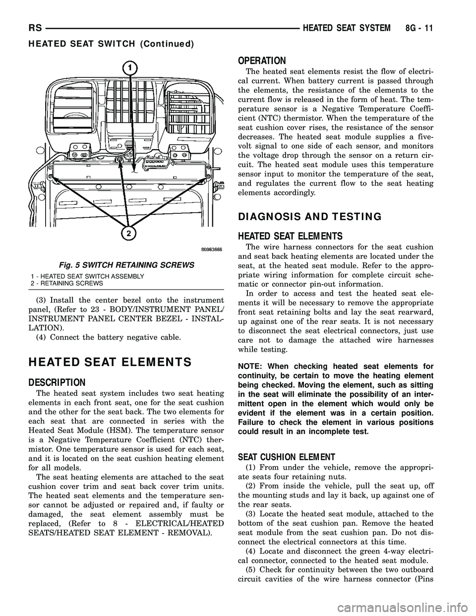
Fig. 5 SWITCH RETAINING SCREWS
1 - HEATED SEAT SWITCH ASSEMBLY
2 - RETAINING SCREWS
RSHEATED SEAT SYSTEM8G-11
HEATED SEAT SWITCH (Continued)
Page 357 of 2339
1&4). There should be continuity. If OK, (Refer to 8 -
ELECTRICAL/ELECTRONIC CONTROL MOD-
ULES/MEMORY HEATED SEAT/MIRROR MOD-
ULE - DIAGNOSIS AND TESTING) for complete
system testing procedures. If not OK, install a
replacement heated seat cushion element, (Refer to 8
- ELECTRICAL/HEATED SEATS/HEATED SEAT
ELEMENT - INSTALLATION).
SEAT BACK ELEMENT
(1) From under the vehicle, remove the appropri-
ate seats four retaining nuts.
(2) From inside the vehicle, pull the seat up and
off the mounting studs and lay it back, up against
one of the rear seats.
(3) Locate the heated seat module, attached to the
bottom of the seat cushion pan. Remove the heated
seat module from the seat cushion pan. Do not dis-
connect the electrical connectors at this time.
(4) Locate and disconnect the gray 2-way electrical
connector, connected to the heated seat module.
(5) Check for continuity between the two circuit
cavities of the 2-way wire harness connector. There
should be continuity. If OK, (Refer to 8 - ELECTRI-
CAL/ELECTRONIC CONTROL MODULES/MEM-
ORY HEATED SEAT/MIRROR MODULE -
DIAGNOSIS AND TESTING) for complete system
testing procedures. If not OK, install a replacement
heated seat back element, (Refer to 8 - ELECTRI-
CAL/HEATED SEATS/HEATED SEAT ELEMENT -
INSTALLATION).
REMOVAL
NOTE: Do not remove the factory installed heating
elements from the seat or seat back cushions. The
original element is permanently attached and can-
not be removed without permanent damage. The
replacement heating element is designed to be
applied directly on top of the factory installed heat-
ing element.
(1) Disconnect and isolate the battery negative
cable.
(2) Remove the appropriate seat cushion or seat
back trim cover.
(3) Disconnect the inoperative heated seat cushion
or seat back element electrical connectors (Fig. 6).
(4) Locate the wires leading from the inoperative
heating element and cut them off flush with the edge
of the original heating element.
INSTALLATION
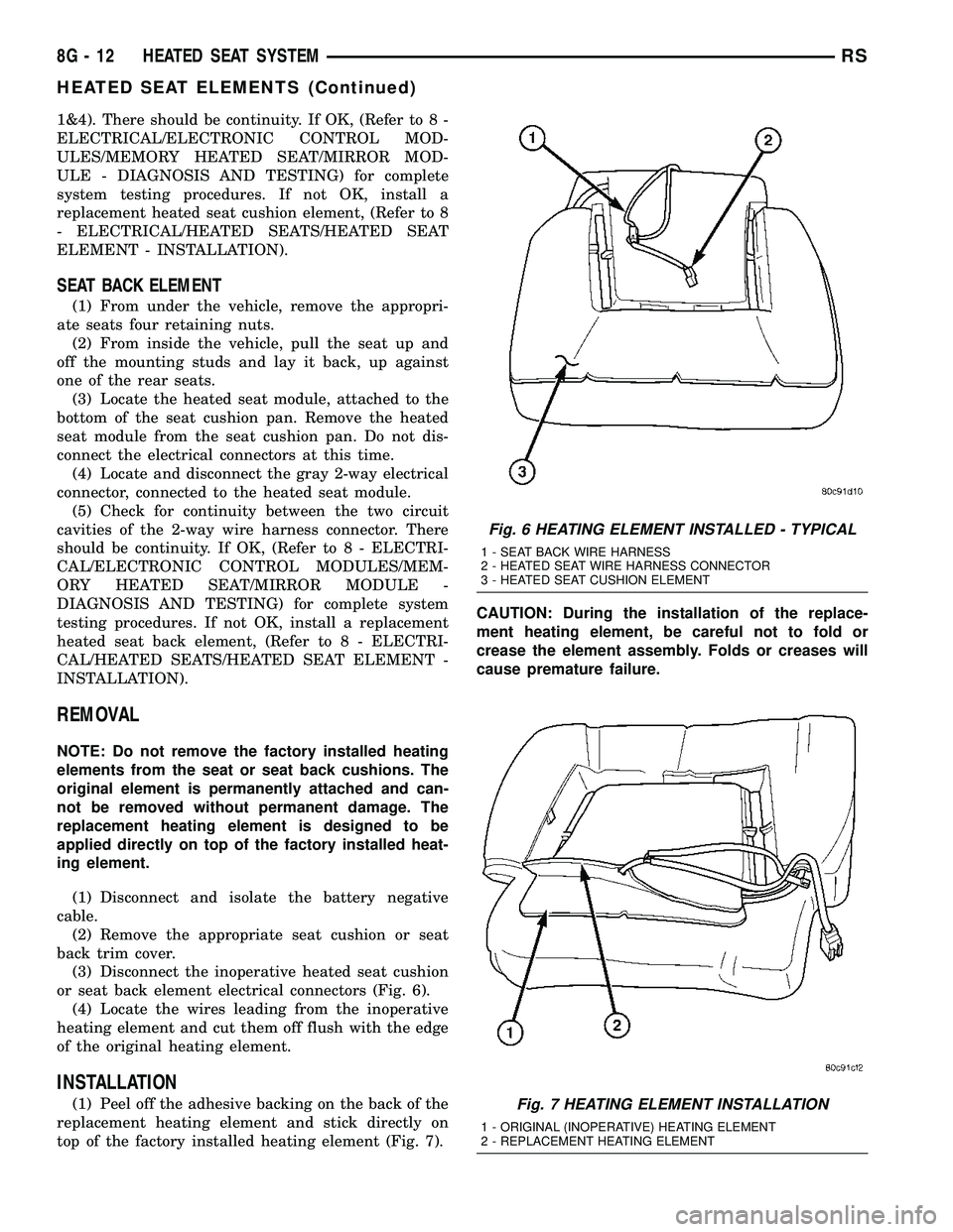
(1) Peel off the adhesive backing on the back of the
replacement heating element and stick directly on
top of the factory installed heating element (Fig. 7).CAUTION: During the installation of the replace-
ment heating element, be careful not to fold or
crease the element assembly. Folds or creases will
cause premature failure.
Fig. 6 HEATING ELEMENT INSTALLED - TYPICAL
1 - SEAT BACK WIRE HARNESS
2 - HEATED SEAT WIRE HARNESS CONNECTOR
3 - HEATED SEAT CUSHION ELEMENT
Fig. 7 HEATING ELEMENT INSTALLATION
1 - ORIGINAL (INOPERATIVE) HEATING ELEMENT
2 - REPLACEMENT HEATING ELEMENT
8G - 12 HEATED SEAT SYSTEMRS
HEATED SEAT ELEMENTS (Continued)
Page 358 of 2339
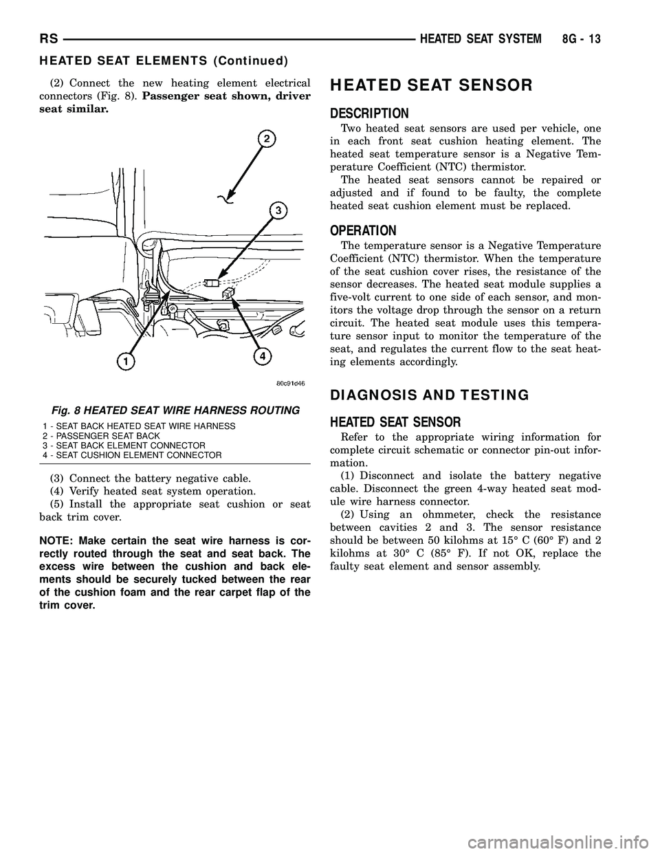
(2) Connect the new heating element electrical
connectors (Fig. 8).Passenger seat shown, driver
seat similar.
(3) Connect the battery negative cable.
(4) Verify heated seat system operation.
(5) Install the appropriate seat cushion or seat
back trim cover.
NOTE: Make certain the seat wire harness is cor-
rectly routed through the seat and seat back. The
excess wire between the cushion and back ele-
ments should be securely tucked between the rear
of the cushion foam and the rear carpet flap of the
trim cover.HEATED SEAT SENSOR
DESCRIPTION
Two heated seat sensors are used per vehicle, one
in each front seat cushion heating element. The
heated seat temperature sensor is a Negative Tem-
perature Coefficient (NTC) thermistor.
The heated seat sensors cannot be repaired or
adjusted and if found to be faulty, the complete
heated seat cushion element must be replaced.
OPERATION
The temperature sensor is a Negative Temperature
Coefficient (NTC) thermistor. When the temperature
of the seat cushion cover rises, the resistance of the
sensor decreases. The heated seat module supplies a
five-volt current to one side of each sensor, and mon-
itors the voltage drop through the sensor on a return
circuit. The heated seat module uses this tempera-
ture sensor input to monitor the temperature of the
seat, and regulates the current flow to the seat heat-
ing elements accordingly.
DIAGNOSIS AND TESTING
HEATED SEAT SENSOR
Refer to the appropriate wiring information for
complete circuit schematic or connector pin-out infor-
mation.
(1) Disconnect and isolate the battery negative
cable. Disconnect the green 4-way heated seat mod-
ule wire harness connector.
(2) Using an ohmmeter, check the resistance
between cavities 2 and 3. The sensor resistance
should be between 50 kilohms at 15É C (60É F) and 2
kilohms at 30É C (85É F). If not OK, replace the
faulty seat element and sensor assembly.
Fig. 8 HEATED SEAT WIRE HARNESS ROUTING
1 - SEAT BACK HEATED SEAT WIRE HARNESS
2 - PASSENGER SEAT BACK
3 - SEAT BACK ELEMENT CONNECTOR
4 - SEAT CUSHION ELEMENT CONNECTOR
RSHEATED SEAT SYSTEM8G-13
HEATED SEAT ELEMENTS (Continued)
Page 360 of 2339
HORN
TABLE OF CONTENTS
page page
HORN SYSTEM
DESCRIPTION..........................1
OPERATION............................1
DIAGNOSIS AND TESTING
HORN SYSTEM........................1
HORN
DIAGNOSIS AND TESTING
HORN...............................3REMOVAL.............................4
INSTALLATION..........................4
HORN SWITCH
DESCRIPTION..........................4
HORN SYSTEM
DESCRIPTION
WARNING: ON VEHICLES EQUIPPED WITH AIR-
BAG, REFER TO ELECTRICAL, RESTRAINTS FOR
SAFETY PRECAUTIONS. DISCONNECT THE NEGA-
TIVE CABLE FROM THE BATTERY BEFORE SER-
VICING COMPONENTS INVOLVING THE AIRBAG
SYSTEM. ACCIDENTAL DEPLOYMENT OF AIRBAG
AND PERSONAL INJURY CAN RESULT.
The horn circuit consists of a horn switch, clock-
spring, horn relay, horns and Integrated Power Mod-
ule (IPM). The horn switch is a membrane switch
located in the airbag trim cover. The horns are
located forward of the left front wheel behind the
bumper fascia.
OPERATION
The horn relay plugs into the Integrated Power
Module (IPM) which is located in the engine com-
partment. For circuit information and component
locations, refer to the appropriate wiring information.
The wiring information includes wiring diagrams,
proper wire and connector repair procedures, details
of wire harness routing and retention, connector pin-
out information and location views for the various
wire harness connectors, splices and grounds.
The horns will not function if the switch is
ªCLOSEDº for more than 30 seconds. Once the
switch is ªOPENº, a 20±30 second delay will occur
before the horns are functional again.
DIAGNOSIS AND TESTING
HORN SYSTEM
WARNING: ON VEHICLES EQUIPPED WITH AIR-
BAGS, REFER TO ELECTRICAL, RESTRAINTS
BEFORE ATTEMPTING ANY STEERING WHEEL,
STEERING COLUMN, OR INSTRUMENT PANEL
COMPONENT DIAGNOSIS OR SERVICE. FAILURE
TO TAKE THE PROPER PRECAUTIONS COULD
RESULT IN ACCIDENTAL AIRBAG DEPLOYMENT
AND POSSIBLE PERSONAL INJURY.
Refer to Horn System Test below. If the horn does
not sound, check horn fuse located in the Integrated
Power Module (IPM). If the fuse is blown, replace
with the correct fuse. If the horns fail to sound and
the new fuse blows when depressing the horn switch,
a short circuit in the horn or the horn wiring
between the fuse terminal and the horn is responsi-
ble, or a defective horn switch allowed the horn to
burn out is responsible.
If the fuse is OK, test horn relay.
If the relay is OK, test horn.
CAUTION: Continuous sounding of horn may
cause horn failure.
Should the horn sound continuously, unplug the
horn relay from IPM.
Refer to the appropriate wiring information.
RSHORN8H-1
Page 361 of 2339

HORN SYSTEM TEST
CONDITION POSSIBLE CAUSE CORRECTION
HORN SOUNDS CONTINUOUSLY.
NOTE: IMMEDIATELY UNPLUG HORN
RELAY IN THE IPM.(1) HORN RELAY
INOPERATIVE.(1) REPLACE RELAY.
(2) HORN CONTROL
CIRCUIT TO RELAY
SHORTED TO GROUND.(2) CHECK TERMINAL 85 IN IPM FOR
CONTINUITY TO GROUND. IF
CONTINUITY TO GROUND INDICATES:
(A) STEERING WHEEL HORN SWITCH/
LEAD SHORTED TO GROUND.
(B) WIRING HARNESS SHORTED TO
GROUND. FIND THE SHORT AND
REPAIR AS NECESSARY.
(3) PINCHED HORN SWITCH
WIRE UNDER DRIVER
AIRBAG MODULE.(3) REPLACE DRIVER AIRBAG TRIM
COVER.
(4) HORN SWITCH
INOPERATIVE.(4) REPLACE DRIVER AIRBAG TRIM
COVER.
(5) CLOCKSPRING
INOPERATIVE.(5) REPLACE CLOCKSPRING.
(6) FRONT CONTROL
MODULE INOPERATIVE.(6) REFER TO ELECTRONIC CONTROL
MODULES/FRONT CONTROL MODULE.
HORN SOUND INTERMITTENTLY AS
THE STEERING WHEEL IS TURNED.(1) HORN RELAY CONTROL
CIRCUIT X3 IS SHORTED TO
GROUND INSIDE STEERING
COLUMN OR WHEEL.(1) REMOVE DRIVER AIRBAG AND/OR
WHEEL. CHECK FOR RUBBING OR
LOOSE WIRE/CONNECTOR, REPAIR AS
NECESSARY.
(2) PINCHED HORN SWITCH
WIRE UNDER DRIVER
AIRBAG MODULE.(2) REPLACE DRIVER AIRBAG TRIM
COVER.
(3) HORN SWITCH
INOPERATIVE.(3) REPLACE DRIVER AIRBAG TRIM
COVER.
(4) CLOCKSPRING
INOPERATIVE.(4) REPLACE CLOCKSPRING.
HORN DOES NOT SOUND (1) CHECK FUSE 8 IN
INTELLIGENT POWER
MODULE.(1) REPLACE FUSE IF BLOWN REPAIR
AS NECESSARY.
(2) NO VOLTAGE AT HORN
RELAY TERMINALS 30 & 86,
AND FUSE IS OK.(2) NO VOLTAGE, REPAIR THE CIRCUIT
AS NECESSARY.
(3) OPEN CIRCUIT FROM
TERMINAL 85 OF THE HORN
RELAY TO HORN SWITCH,
X3 CIRCUIT.(3) REPAIR CIRCUIT AS NECESSARY.
(4) HORN INOPERATIVE OR
DAMAGED.(4) CHECK VOLTAGE AT HORN WHEN
HORN SWITCH IS PRESSED. IF NO
VOLTAGE, REPLACE HORN.
(5) HORN SWITCH
INOPERATIVE.(5) REPLACE DRIVER AIRBAG TRIM
COVER.
8H - 2 HORNRS
HORN SYSTEM (Continued)