Module CHRYSLER VOYAGER 2005 Workshop Manual
[x] Cancel search | Manufacturer: CHRYSLER, Model Year: 2005, Model line: VOYAGER, Model: CHRYSLER VOYAGER 2005Pages: 2339, PDF Size: 59.69 MB
Page 318 of 2339
twenty amperes or more will require a shorter charg-
ing time.
²State-Of-Charge- A completely discharged bat-
tery requires more charging time than a partially
discharged battery. Electrolyte is nearly pure water
in a completely discharged battery. At first, the
charging current (amperage) will be low. As the bat-
tery charges, the specific gravity of the electrolyte
will gradually rise.
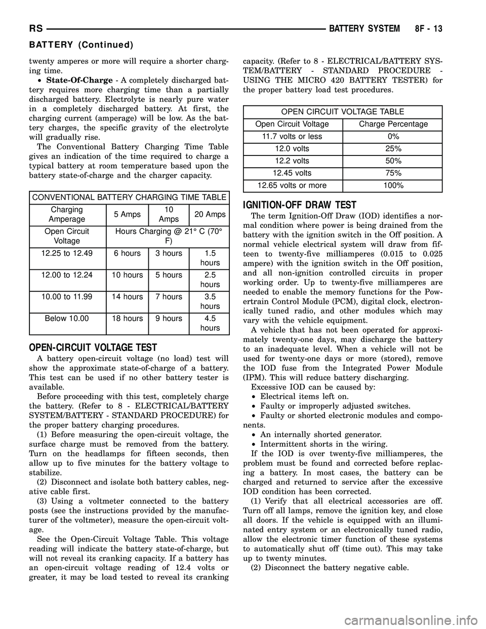
The Conventional Battery Charging Time Table
gives an indication of the time required to charge a
typical battery at room temperature based upon the
battery state-of-charge and the charger capacity.
CONVENTIONAL BATTERY CHARGING TIME TABLE
Charging
Amperage5 Amps10
Amps20 Amps
Open Circuit
VoltageHours Charging @ 21É C (70É
F)
12.25 to 12.49 6 hours 3 hours 1.5
hours
12.00 to 12.24 10 hours 5 hours 2.5
hours
10.00 to 11.99 14 hours 7 hours 3.5
hours
Below 10.00 18 hours 9 hours 4.5
hours
OPEN-CIRCUIT VOLTAGE TEST
A battery open-circuit voltage (no load) test will
show the approximate state-of-charge of a battery.
This test can be used if no other battery tester is
available.
Before proceeding with this test, completely charge
the battery. (Refer to 8 - ELECTRICAL/BATTERY
SYSTEM/BATTERY - STANDARD PROCEDURE) for
the proper battery charging procedures.
(1) Before measuring the open-circuit voltage, the
surface charge must be removed from the battery.
Turn on the headlamps for fifteen seconds, then
allow up to five minutes for the battery voltage to
stabilize.
(2) Disconnect and isolate both battery cables, neg-
ative cable first.
(3) Using a voltmeter connected to the battery
posts (see the instructions provided by the manufac-
turer of the voltmeter), measure the open-circuit volt-
age.
See the Open-Circuit Voltage Table. This voltage
reading will indicate the battery state-of-charge, but
will not reveal its cranking capacity. If a battery has
an open-circuit voltage reading of 12.4 volts or
greater, it may be load tested to reveal its crankingcapacity. (Refer to 8 - ELECTRICAL/BATTERY SYS-
TEM/BATTERY - STANDARD PROCEDURE -
USING THE MICRO 420 BATTERY TESTER) for
the proper battery load test procedures.
OPEN CIRCUIT VOLTAGE TABLE
Open Circuit Voltage Charge Percentage
11.7 volts or less 0%
12.0 volts 25%
12.2 volts 50%
12.45 volts 75%
12.65 volts or more 100%
IGNITION-OFF DRAW TEST
The term Ignition-Off Draw (IOD) identifies a nor-
mal condition where power is being drained from the
battery with the ignition switch in the Off position. A
normal vehicle electrical system will draw from fif-
teen to twenty-five milliamperes (0.015 to 0.025
ampere) with the ignition switch in the Off position,
and all non-ignition controlled circuits in proper
working order. Up to twenty-five milliamperes are
needed to enable the memory functions for the Pow-
ertrain Control Module (PCM), digital clock, electron-
ically tuned radio, and other modules which may
vary with the vehicle equipment.
A vehicle that has not been operated for approxi-
mately twenty-one days, may discharge the battery
to an inadequate level. When a vehicle will not be
used for twenty-one days or more (stored), remove
the IOD fuse from the Integrated Power Module
(IPM). This will reduce battery discharging.
Excessive IOD can be caused by:
²Electrical items left on.
²Faulty or improperly adjusted switches.
²Faulty or shorted electronic modules and compo-
nents.
²An internally shorted generator.
²Intermittent shorts in the wiring.
If the IOD is over twenty-five milliamperes, the
problem must be found and corrected before replac-
ing a battery. In most cases, the battery can be
charged and returned to service after the excessive
IOD condition has been corrected.
(1) Verify that all electrical accessories are off.
Turn off all lamps, remove the ignition key, and close
all doors. If the vehicle is equipped with an illumi-
nated entry system or an electronically tuned radio,
allow the electronic timer function of these systems
to automatically shut off (time out). This may take
up to twenty minutes.
(2) Disconnect the battery negative cable.
RSBATTERY SYSTEM8F-13
BATTERY (Continued)
Page 319 of 2339

(3) Set an electronic digital multi-meter to its
highest amperage scale. Connect the multi-meter
between the disconnected battery negative cable ter-
minal clamp and the battery negative terminal post.
Make sure that the doors remain closed so that the
illuminated entry system is not activated. The multi-
meter amperage reading may remain high for up to
three minutes, or may not give any reading at all
while set in the highest amperage scale, depending
upon the electrical equipment in the vehicle. The
multi-meter leads must be securely clamped to the
battery negative cable terminal clamp and the bat-
tery negative terminal post. If continuity between the
battery negative terminal post and the negative cable
terminal clamp is lost during any part of the IOD
test, the electronic timer function will be activated
and all of the tests will have to be repeated.
(4) After about three minutes, the high-amperage
IOD reading on the multi-meter should become very
low or nonexistent, depending upon the electrical
equipment in the vehicle. If the amperage reading
remains high, remove and replace each fuse or circuit
breaker in the Integrated Power Module (IPM), one
at a time until the amperage reading becomes very
low, or nonexistent. Refer to the appropriate wiring
information for complete Integrated Power Module
fuse, circuit breaker, and circuit identification. This
will isolate each circuit and identify the circuit that
is the source of the high-amperage IOD. If the
amperage reading remains high after removing and
replacing each fuse and circuit breaker, disconnect
the wire harness from the generator. If the amperage
reading now becomes very low or nonexistent, (Refer
to 8 - ELECTRICAL/CHARGING - DIAGNOSIS AND
TESTING) for the proper charging system diagnosis
and testing procedures. After the high-amperage IOD
has been corrected, switch the multi-meter to pro-
gressively lower amperage scales and, if necessary,
repeat the fuse and circuit breaker remove-and-re-
place process to identify and correct all sources of
excessive IOD. It is now safe to select the lowest mil-
liampere scale of the multi-meter to check the low-
amperage IOD.
CAUTION: Do not open any doors, or turn on any
electrical accessories with the lowest milliampere
scale selected, or the multi-meter may be damaged.
(5) Allow twenty minutes for the IOD to stabilize
and observe the multi-meter reading. The low-amper-age IOD should not exceed twenty-five milliamperes
(0.025 ampere). If the current draw exceeds twenty-
five milliamperes, isolate each circuit using the fuse
and circuit breaker remove-and-replace process in
Step 4. The multi-meter reading will drop to within
the acceptable limit when the source of the excessive
current draw is disconnected. Repair this circuit as
required; whether a wiring short, incorrect switch
adjustment, or a component failure is at fault.
CHECKING BATTERY ELECTROLYTE LEVEL
The following procedure can be used to check the
electrolyte level in a low-maintenance lead-acid bat-
tery.
(1) Unscrew and remove the battery cell caps with
a flat-bladed screw driver (Fig. 9).
WARNING: NEVER PUT YOUR FACE NEAR A GAS-
SING, HOT OR SWELLED BATTERY. SERIOUS PER-
SONAL INJURY MAY RESULT.
Fig. 9 BATTERY CELL CAP REMOVAL/
INSTALLATION - LOW-MAINTENANCE BATTERY
ONLY
1 - BATTERY CELL CAP
2 - BATTERY CASE
8F - 14 BATTERY SYSTEMRS
BATTERY (Continued)
Page 321 of 2339
press the ENTER button to view the SERVICE
CODE. Pressing the CODE button a second time will
return you to the test results.
BATTERY TEST RESULTS
GOOD BATTERY Return to service
GOOD - RECHARGE Fully charge battery and
return to service
CHARGE & RETEST Fully charge battery and
retest battery
REPLACE BATTERY Replace the battery and
retest complete system
BAD-CELL REPLACE Replace the battery and
retest complete system
NOTE: The SERVICE CODE is required on every
warranty claim submitted for battery replacement.
REMOVAL - BATTERY
WARNING: A SUITABLE PAIR OF HEAVY DUTY
RUBBER GLOVES AND SAFETY GLASSES SHOULD
BE WORN WHEN REMOVING OR SERVICING A
BATTERY.
WARNING: REMOVE METALLIC JEWELRY TO
AVOID INJURY BY ACCIDENTAL ARCING OF BAT-
TERY CURRENT.
(1) Verify that the ignition switch and all accesso-
ries are OFF.
(2) Disconnect the battery cables from the battery
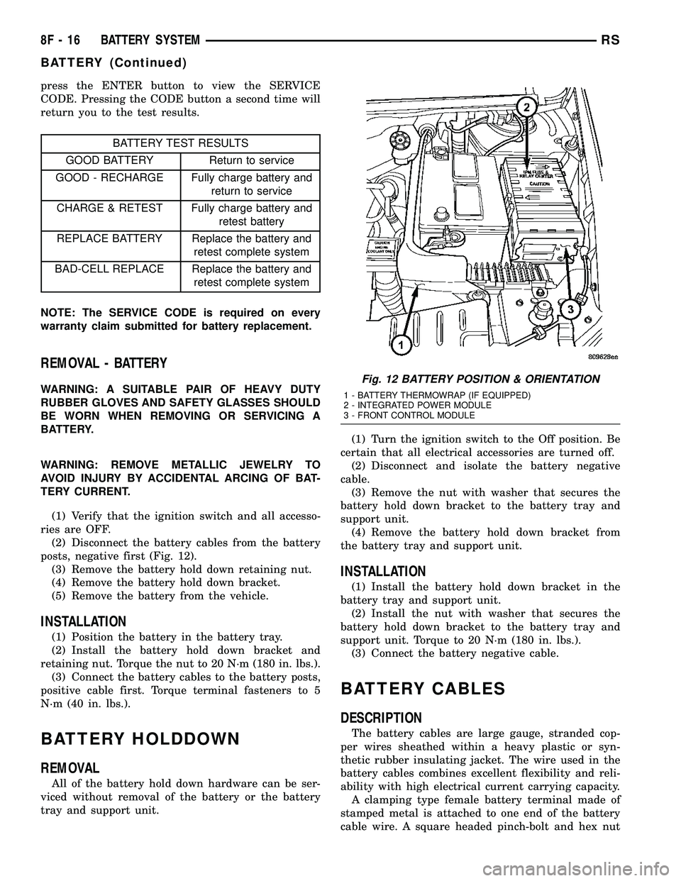
posts, negative first (Fig. 12).
(3) Remove the battery hold down retaining nut.
(4) Remove the battery hold down bracket.
(5) Remove the battery from the vehicle.
INSTALLATION
(1) Position the battery in the battery tray.
(2) Install the battery hold down bracket and
retaining nut. Torque the nut to 20 N´m (180 in. lbs.).
(3) Connect the battery cables to the battery posts,
positive cable first. Torque terminal fasteners to 5
N´m (40 in. lbs.).
BATTERY HOLDDOWN
REMOVAL
All of the battery hold down hardware can be ser-
viced without removal of the battery or the battery
tray and support unit.(1) Turn the ignition switch to the Off position. Be
certain that all electrical accessories are turned off.
(2) Disconnect and isolate the battery negative
cable.
(3) Remove the nut with washer that secures the
battery hold down bracket to the battery tray and
support unit.
(4) Remove the battery hold down bracket from
the battery tray and support unit.
INSTALLATION
(1) Install the battery hold down bracket in the
battery tray and support unit.
(2) Install the nut with washer that secures the
battery hold down bracket to the battery tray and
support unit. Torque to 20 N´m (180 in. lbs.).
(3) Connect the battery negative cable.
BATTERY CABLES
DESCRIPTION
The battery cables are large gauge, stranded cop-
per wires sheathed within a heavy plastic or syn-
thetic rubber insulating jacket. The wire used in the
battery cables combines excellent flexibility and reli-
ability with high electrical current carrying capacity.
A clamping type female battery terminal made of
stamped metal is attached to one end of the battery
cable wire. A square headed pinch-bolt and hex nut
Fig. 12 BATTERY POSITION & ORIENTATION
1 - BATTERY THERMOWRAP (IF EQUIPPED)
2 - INTEGRATED POWER MODULE
3 - FRONT CONTROL MODULE
8F - 16 BATTERY SYSTEMRS
BATTERY (Continued)
Page 322 of 2339
are installed at the open end of the female battery
terminal clamp. Large eyelet type terminals are
crimped onto the opposite end of the battery cable
wire and then solder-dipped. The battery positive
cable wires have a red insulating jacket to provide
visual identification and feature a larger female bat-
tery terminal clamp to allow connection to the larger
battery positive terminal post. The battery negative
cable wires have a black insulating jacket and a
smaller female battery terminal clamp.
The battery cables cannot be repaired and, if dam-
aged or faulty they must be replaced. Both the bat-
tery positive and negative cables are available for
service replacement only as a unit with the battery
wire harness, which may include portions of the wir-
ing circuits for the generator and other components
on some vehicles. Refer to the appropriate wiring
information for complete circuit schematic or connec-
tor pin-out information.
OPERATION
The battery cables connect the battery terminal
posts to the vehicle electrical system. These cables
also provide a path back to the battery for electrical
current generated by the charging system for restor-
ing the voltage potential of the battery. The female
battery terminal clamps on the ends of the battery
cable wires provide a strong and reliable connection
of the battery cable to the battery terminal posts.
The terminal pinch bolts allow the female terminal
clamps to be tightened around the male terminal
posts on the top of the battery. The eyelet terminals
secured to the opposite ends of the battery cable
wires from the female battery terminal clamps pro-
vide secure and reliable connection of the battery
cables to the vehicle electrical system.
The battery positive cable terminal clamp is
attached to the ends of two wires. One wire has an
eyelet terminal that connects the battery positive
cable to the B(+) terminal stud of the Integrated
Power Module (IPM), and the other wire has an eye-
let terminal that connects the battery positive cable
to the B(+) terminal stud of the engine starter motor
solenoid. The battery negative cable terminal clamp
is also attached to the ends of two wires. One wire
has an eyelet terminal that connects the battery neg-
ative cable to the vehicle powertrain through a stud
on the left side of the engine cylinder block. The
other wire has an eyelet terminal that connects the
battery negative cable to the vehicle body through a
ground screw on the left front fender inner shield,
near the battery.
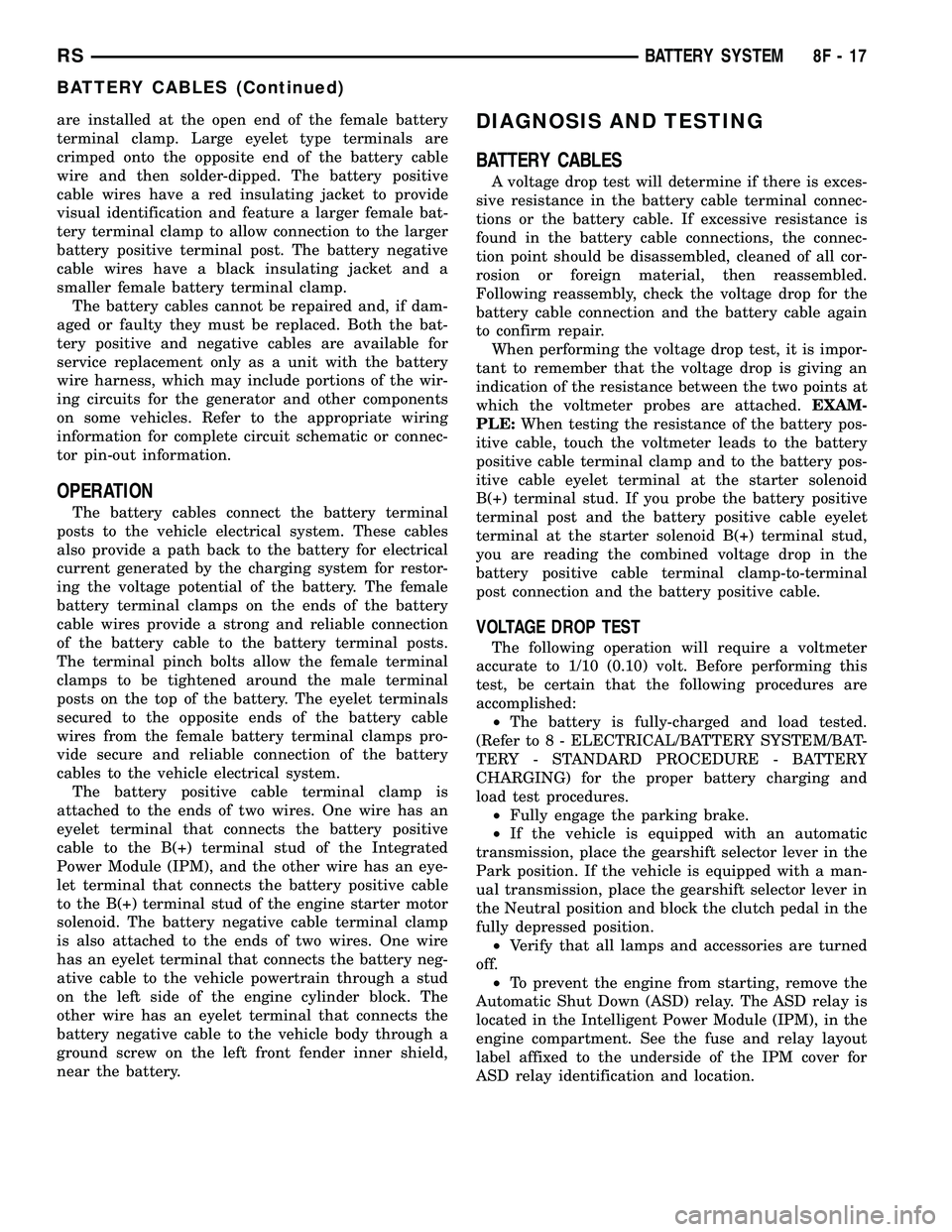
DIAGNOSIS AND TESTING
BATTERY CABLES
A voltage drop test will determine if there is exces-
sive resistance in the battery cable terminal connec-
tions or the battery cable. If excessive resistance is
found in the battery cable connections, the connec-
tion point should be disassembled, cleaned of all cor-
rosion or foreign material, then reassembled.
Following reassembly, check the voltage drop for the
battery cable connection and the battery cable again
to confirm repair.
When performing the voltage drop test, it is impor-
tant to remember that the voltage drop is giving an
indication of the resistance between the two points at
which the voltmeter probes are attached.EXAM-
PLE:When testing the resistance of the battery pos-
itive cable, touch the voltmeter leads to the battery
positive cable terminal clamp and to the battery pos-
itive cable eyelet terminal at the starter solenoid
B(+) terminal stud. If you probe the battery positive
terminal post and the battery positive cable eyelet
terminal at the starter solenoid B(+) terminal stud,
you are reading the combined voltage drop in the
battery positive cable terminal clamp-to-terminal
post connection and the battery positive cable.
VOLTAGE DROP TEST
The following operation will require a voltmeter
accurate to 1/10 (0.10) volt. Before performing this
test, be certain that the following procedures are
accomplished:
²The battery is fully-charged and load tested.
(Refer to 8 - ELECTRICAL/BATTERY SYSTEM/BAT-
TERY - STANDARD PROCEDURE - BATTERY
CHARGING) for the proper battery charging and
load test procedures.
²Fully engage the parking brake.
²If the vehicle is equipped with an automatic
transmission, place the gearshift selector lever in the
Park position. If the vehicle is equipped with a man-
ual transmission, place the gearshift selector lever in
the Neutral position and block the clutch pedal in the
fully depressed position.
²Verify that all lamps and accessories are turned
off.
²To prevent the engine from starting, remove the
Automatic Shut Down (ASD) relay. The ASD relay is
located in the Intelligent Power Module (IPM), in the
engine compartment. See the fuse and relay layout
label affixed to the underside of the IPM cover for
ASD relay identification and location.
RSBATTERY SYSTEM8F-17
BATTERY CABLES (Continued)
Page 326 of 2339
CHARGING
TABLE OF CONTENTS
page page
CHARGING
DESCRIPTION - CHARGING SYSTEM.......21
OPERATION - CHARGING SYSTEM.........21
DIAGNOSIS AND TESTING
ON-BOARD DIAGNOSTIC SYSTEM........22
SPECIFICATIONS
GENERATOR........................23
TORQUE............................23
SPECIFICATIONS - BATTERY
TEMPERATURE SENSOR...............23
SPECIAL TOOLS.......................24
BATTERY TEMPERATURE SENSOR
DESCRIPTION.........................24
OPERATION...........................24
REMOVAL.............................24
GENERATOR
DESCRIPTION.........................24
OPERATION...........................24REMOVAL
REMOVAL - 2.4L......................24
REMOVAL - 2.5L......................25
REMOVAL - 3.3/3.8L...................27
INSTALLATION
INSTALLATION - 2.4L..................27
INSTALLATION - 2.5L..................27
INSTALLATION - 3.3/3.8L................27
GENERATOR DECOUPLER PULLEY
DESCRIPTION.........................28
OPERATION...........................28
DIAGNOSIS AND TESTING - GENERATOR
DECOUPLER PULLEY..................28
REMOVAL.............................29
INSTALLATION.........................29
VOLTAGE REGULATOR
DESCRIPTION.........................30
OPERATION...........................30
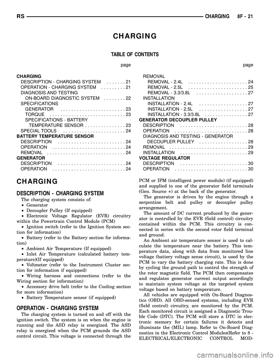
CHARGING
DESCRIPTION - CHARGING SYSTEM
The charging system consists of:
²Generator
²Decoupler Pulley (If equipped)
²Electronic Voltage Regulator (EVR) circuitry
within the Powertrain Control Module (PCM)
²Ignition switch (refer to the Ignition System sec-
tion for information)
²Battery (refer to the Battery section for informa-
tion)
²Ambient Air Temperature (If equipped)
²Inlet Air Temperature (calculated battery tem-
perature)(If equipped)
²Voltmeter (refer to the Instrument Cluster sec-
tion for information if equipped)
²Wiring harness and connections (refer to the
Wiring section for information)
²Accessory drive belt (refer to the Cooling section
for more information)
²Battery Temperature sensor (if equipped)
OPERATION - CHARGING SYSTEM
The charging system is turned on and off with the
ignition switch. The system is on when the engine is
running and the ASD relay is energized. The ASD
relay is energized when the PCM grounds the ASD
control circuit. This voltage is connected through thePCM or IPM (intelligent power module) (if equipped)
and supplied to one of the generator field terminals
(Gen. Source +) at the back of the generator.
The generator is driven by the engine through a
serpentine belt and pulley or decoupler pulley
arrangement.
The amount of DC current produced by the gener-
ator is controlled by the EVR (field control) circuitry
contained within the PCM. This circuitry is con-
nected in series with the second rotor field terminal
and ground.
An Ambient air temperature sensor is used to cal-
culate the temperature near the battery. This tem-
perature data, along with data from monitored line
voltage (battery voltage sense circuit), is used by the
PCM to vary the battery charging rate. This is done
by cycling the ground path to control the strength of
the rotor magnetic field. The PCM then compensates
and regulates generator current output accordingly
to maintain system voltage at the targeted system
voltage based on battery temperature.
All vehicles are equipped with On-Board Diagnos-
tics (OBD). All OBD-sensed systems, including EVR
(field control) circuitry, are monitored by the PCM.
Each monitored circuit is assigned a Diagnostic Trou-
ble Code (DTC). The PCM will store a DTC in elec-
tronic memory for certain failures it detects and
illuminate the (MIL) lamp. Refer to On-Board Diag-
nostics in the Electronic Control Modules(Refer to 8 -
ELECTRICAL/ELECTRONIC CONTROL MOD-
RSCHARGING8F-21
Page 327 of 2339
ULES/POWERTRAIN CONTROL MODULE -
DESCRIPTION) section for more DTC information.
The Charging system ªBatteryº light indicates
problems with the charging system (voltage too high/
low, generator failure, etc.). If an extreme condition is
indicated, the lamp will be illuminated. The signal to
activate the lamp is sent via the PCI bus circuits.
The lamp is located on the instrument panel. Refer
to the Instrument Cluster section for additional infor-
mation.
The PCM uses the ambient air temperature sensor
to control the charge system voltage. This tempera-
ture, along with data from monitored line voltage, is
used by the PCM to vary the battery charging rate.
The system voltage is higher at cold temperatures
and is gradually reduced as the calculated battery
temperature increases.
The ambient temperature sensor is used to control
the battery voltage based upon ambient temperature
(approximation of battery temperature). The PCM
maintains the optimal output of the generator by
monitoring battery voltage and controlling it to a
range of 13.5 - 14.7 volts based on battery tempera-
ture.
DIAGNOSIS AND TESTING
ON-BOARD DIAGNOSTIC SYSTEM
The Powertrain Control Module (PCM) monitors
critical input and output circuits of the charging sys-
tem, making sure they are operational. A Diagnostic
Trouble Code (DTC) is assigned to each input and
output circuit monitored by the OBD system. Some
circuits are checked continuously and some are
checked only under certain conditions.
If the OBD system senses that a monitored circuit
is bad, it will put a DTC into electronic memory. The
DTC will stay in electronic memory as long as the
circuit continues to be bad. The PCM is programmed
to clear the memory after 40 good trip if the problem
does not occur again.
DIAGNOSTIC TROUBLE CODES
A DTC description can be read using the DRBIIIt
scan tool. Refer to the appropriate Powertrain Diag-
nostic Procedures manual for information.
A DTC does not identify which component in a cir-
cuit is bad. Thus, a DTC should be treated as a
symptom, not as the cause for the problem. In some
cases, because of the design of the diagnostic test
procedure, a DTC can be the reason for another DTC
to be set. Therefore, it is important that the test pro-
cedures be followed in sequence, to understand what
caused a DTC to be set.ERASING DIAGNOSTIC TROUBLE CODES
The DRBIIItScan Tool must be used to erase a
DTC.
The following procedures may be used to diagnose
the charging system if:
²the check gauges lamp or battery lamp is illumi-
nated with the engine running
²the voltmeter (if equipped) does not register
properly
²an undercharged or overcharged battery condi-
tion occurs.
Remember that an undercharged battery is often
caused by:
²accessories being left on with the engine not
running
²a faulty or improperly adjusted switch that
allows a lamp to stay on. Refer to Ignition-Off Draw
Test (Refer to 8 - ELECTRICAL/BATTERY SYSTEM/
BATTERY - STANDARD PROCEDURE)
²loose generator belt.
INSPECTION
The Powertrain Control Module (PCM) monitors
critical input and output circuits of the charging sys-
tem, making sure they are operational. A Diagnostic
Trouble Code (DTC) is assigned to each input and
output circuit monitored by the On-Board Diagnostic
(OBD) system. Some charging system circuits are
checked continuously, and some are checked only
under certain conditions.
Refer to Diagnostic Trouble Codes in; Powertrain
Diagnostic manual for more DTC information. This
will include a complete list of DTC's including DTC's
for the charging system.
To perform a complete test of the charging system,
refer to the appropriate Powertrain Diagnostic Proce-
dures service manual and the DRBIIItscan tool.
Perform the following inspections before attaching
the scan tool.
(1) Inspect the battery condition. Refer to the Bat-
tery section (Refer to 8 - ELECTRICAL/BATTERY
SYSTEM - DIAGNOSIS AND TESTING) for proce-
dures.
(2) Inspect condition of battery cable terminals,
battery posts, connections at engine block, starter
solenoid and relay. They should be clean and tight.
Repair as required.
(3) Inspect all fuses in both the fuseblock and
Power Distribution Center (PDC) or IPM (if
equipped) for tightness in receptacles. They should be
properly installed and tight. Repair or replace as
required.
(4) Inspect generator mounting bolts for tightness.
Replace or tighten bolts if required. Refer to the Gen-
erator Removal/Installation section of this group for
8F - 22 CHARGINGRS
CHARGING (Continued)
Page 335 of 2339

(7) Install the right front lower splash shield.
(8) Lower vehicle.
(9) Connect battery negative cable.
VOLTAGE REGULATOR
DESCRIPTION
The Electronic Voltage Regulator (EVR) is not a
separate component. It is actually a voltage regulat-ing circuit located within the Powertrain Control
Module (PCM). The EVR is not serviced separately. If
replacement is necessary, the PCM must be replaced.
OPERATION
The amount of DC current produced by the gener-
ator is controlled by EVR circuitry contained within
the PCM. This circuitry is connected in series with
the generators second rotor field terminal and its
ground.
Voltage is regulated within the PCM on the NGC
vehicles, to control the strength of the rotor magnetic
field. The EVR circuitry monitors system line voltage
at the PDC and calculated battery temperature or
inlet air temperature sensor (refer to Inlet Air Tem-
perature Sensor, if equipped, for more information ).
It then determines a target charging voltage. If
sensed battery voltage is lower than the target volt-
age, the PCM feeds the field winding until sensed
battery voltage is at the target voltage. A circuit in
the PCM cycles the feed side of the generator field at
250 times per second (250Hz), but has the capability
to feed the field control wire 100% of the time (full
field) to achieve the target voltage. If the charging
rate cannot be monitored (limp-in), a duty cycle of
20% is used by the PCM in order to have some gen-
erator output. Also refer to Charging System Opera-
tion for additional information.
Fig. 15 DECOUPLER INSTALLATION (Litens)
8F - 30 CHARGINGRS
GENERATOR DECOUPLER PULLEY (Continued)
Page 338 of 2339
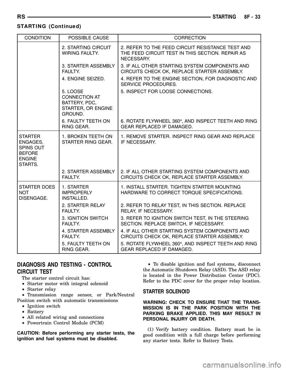
CONDITION POSSIBLE CAUSE CORRECTION
2. STARTING CIRCUIT
WIRING FAULTY.2. REFER TO THE FEED CIRCUIT RESISTANCE TEST AND
THE FEED CIRCUIT TEST IN THIS SECTION. REPAIR AS
NECESSARY.
3. STARTER ASSEMBLY
FAULTY.3. IF ALL OTHER STARTING SYSTEM COMPONENTS AND
CIRCUITS CHECK OK, REPLACE STARTER ASSEMBLY.
4. ENGINE SEIZED. 4. REFER TO THE ENGINE SECTION, FOR DIAGNOSTIC AND
SERVICE PROCEDURES.
5. LOOSE
CONNECTION AT
BATTERY, PDC,
STARTER, OR ENGINE
GROUND.5. INSPECT FOR LOOSE CONNECTIONS.
6. FAULTY TEETH ON
RING GEAR.6. ROTATE FLYWHEEL 360É, AND INSPECT TEETH AND RING
GEAR REPLACED IF DAMAGED.
STARTER
ENGAGES,
SPINS OUT
BEFORE
ENGINE
STARTS.1. BROKEN TEETH ON
STARTER RING GEAR.1. REMOVE STARTER. INSPECT RING GEAR AND REPLACE
IF NECESSARY.
2. STARTER ASSEMBLY
FAULTY.2. IF ALL OTHER STARTING SYSTEM COMPONENTS AND
CIRCUITS CHECK OK, REPLACE STARTER ASSEMBLY.
STARTER DOES
NOT
DISENGAGE.1. STARTER
IMPROPERLY
INSTALLED.1. INSTALL STARTER. TIGHTEN STARTER MOUNTING
HARDWARE TO CORRECT TORQUE SPECIFICATIONS.
2. STARTER RELAY
FAULTY.2. REFER TO RELAY TEST, IN THIS SECTION. REPLACE
RELAY, IF NECESSARY.
3. IGNITION SWITCH
FAULTY.3. REFER TO IGNITION SWITCH TEST, IN THE STEERING
SECTION. REPLACE SWITCH, IF NECESSARY.
4. STARTER ASSEMBLY
FAULTY.4. IF ALL OTHER STARTING SYSTEM COMPONENTS AND
CIRCUITS CHECK OK, REPLACE STARTER ASSEMBLY.
5. FAULTY TEETH ON
RING GEAR.5. ROTATE FLYWHEEL 360É, AND INSPECT TEETH AND RING
GEAR REPLACED IF DAMAGED.
DIAGNOSIS AND TESTING - CONTROL
CIRCUIT TEST
The starter control circuit has:
²Starter motor with integral solenoid
²Starter relay
²Transmission range sensor, or Park/Neutral
Position switch with automatic transmissions
²Ignition switch
²Battery
²All related wiring and connections
²Powertrain Control Module (PCM)
CAUTION: Before performing any starter tests, the
ignition and fuel systems must be disabled.²To disable ignition and fuel systems, disconnect
the Automatic Shutdown Relay (ASD). The ASD relay
is located in the Power Distribution Center (PDC).
Refer to the PDC cover for the proper relay location.
STARTER SOLENOID
WARNING: CHECK TO ENSURE THAT THE TRANS-
MISSION IS IN THE PARK POSITION WITH THE
PARKING BRAKE APPLIED. THIS MAY RESULT IN
PERSONAL INJURY OR DEATH.
(1) Verify battery condition. Battery must be in
good condition with a full charge before performing
any starter tests. Refer to Battery Tests.
RSSTARTING8F-33
STARTING (Continued)
Page 346 of 2339
HEATED SYSTEMS
TABLE OF CONTENTS
page page
HEATED GLASS........................... 1
HEATED MIRRORS......................... 6HEATED SEAT SYSTEM..................... 7
HEATED GLASS
TABLE OF CONTENTS
page page
HEATED GLASS
DESCRIPTION..........................1
OPERATION............................2
DIAGNOSIS AND TESTING
ELECTRIC BACKLIGHT (EBL) SYSTEM.....2
REAR WINDOW DEFOGGER RELAY
DESCRIPTION..........................3
OPERATION............................3REMOVAL.............................4
INSTALLATION..........................4
REAR WINDOW DEFOGGER SWITCH
DESCRIPTION..........................4
OPERATION............................4
REAR WINDOW DEFOGGER GRID
STANDARD PROCEDURE
GRID REPAIR PROCEDURE..............5
HEATED GLASS
DESCRIPTION
CAUTION: Grid lines can be damaged or scraped
off with sharp instruments. Care should be taken in
cleaning glass or removing foreign materials,
decals or stickers. Normal glass cleaning solvents
or hot water used with rags or toweling is recom-
mended.
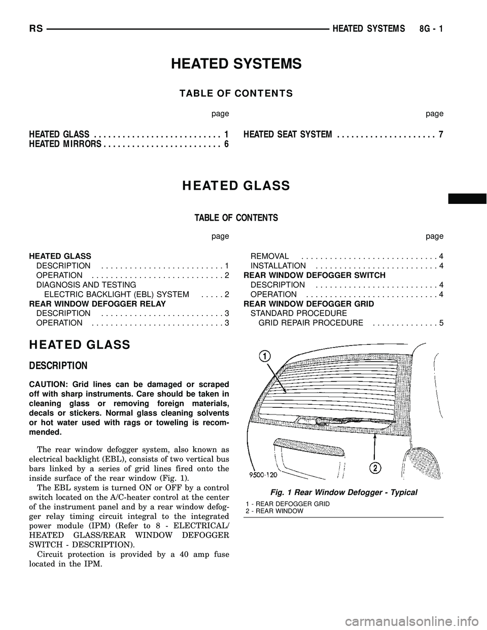
The rear window defogger system, also known as
electrical backlight (EBL), consists of two vertical bus
bars linked by a series of grid lines fired onto the
inside surface of the rear window (Fig. 1).
The EBL system is turned ON or OFF by a control
switch located on the A/C-heater control at the center
of the instrument panel and by a rear window defog-
ger relay timing circuit integral to the integrated
power module (IPM) (Refer to 8 - ELECTRICAL/
HEATED GLASS/REAR WINDOW DEFOGGER
SWITCH - DESCRIPTION).
Circuit protection is provided by a 40 amp fuse
located in the IPM.
Fig. 1 Rear Window Defogger - Typical
1 - REAR DEFOGGER GRID
2 - REAR WINDOW
RSHEATED SYSTEMS8G-1
Page 347 of 2339
OPERATION
When the rear window defogger button is
depressed to the On position, current is directed to
the rear defogger grid lines and the heated power
mirrors (if equipped). The heated grid lines heat the
glass to help clear the rear window and side mirror
surfaces of fog or frost.
The electric backlight (EBL) system is controlled
by a momentary switch located in the A/C-heater
control on the instrument panel. A yellow indicator in
the switch will illuminate to indicate when the sys-
tem is turned on. The integrated power module (IPM)
contains the EBL system control circuitry.
NOTE: The rear window defogger turns off automat-
ically after approximately 10 minutes of initial oper-
ation. Each following activation cycle of the
defogger system will last approximately five min-
utes.
The EBL system will be automatically turned off
after a programmed time interval of about ten min-
utes. After the initial time interval has expired, if the
defogger switch is turned on again during the same
ignition cycle, the defogger system will automatically
turn off after about five minutes.
The EBL system will automatically shut off if the
ignition switch is turned to the Off position, or it can
be turned off manually by depressing the defogger
switch a second time.
DIAGNOSIS AND TESTING
ELECTRIC BACKLIGHT (EBL) SYSTEM
NOTE: Illumination of the defogger switch indicator
lamp means that there is electrical current available
at the output of the rear window defogger logic cir-
cuitry, but does not confirm that the electrical cur-
rent is reaching the rear glass heating grid lines.
NOTE: For circuit descriptions and diagrams of the
rear window defogger system, refer to 8W - WIRING
DIAGRAM INFORMATION.
Operation of the electrical backlight (EBL) system
can be confirmed by the following:(1) Turn the ignition switch to the On position. Set
the defogger switch in the On position. The rear win-
dow defogger operation can be checked by feeling the
rear window glass. A distinct difference in tempera-
ture between the grid lines and the adjacent clear
glass can be detected within three to four minutes of
operation.
(2) If a temperature difference is not detected, use
a 12-volt DC voltmeter and contact the rear glass
heating grid terminal B with the negative lead, and
terminal A with the positive lead (Fig. 2). The volt-
meter should read battery voltage. If the voltmeter
does not read battery voltage, check the following:
²Confirm that the ignition switch is in the On
position.
²Make sure that the rear glass heating grid feed
wire and ground wire are connected to the terminals.
Confirm that the ground wire has continuity to
ground.
²Check that fuse 13 (40 amp) in the integrated
power module (IPM) is OK. The fuse must be tight in
it's receptacle and all electrical connections must be
secure.
(3) When the above steps have been completed and
the rear glass heating grid is still inoperative, one or
more of the following is faulty. It may be necessary to
connect a DRBIIItscan tool to perform further diag-
nostics. Refer to Body Diagnostic Procedures.
²Rear window defogger switch in the A/C-heater
control.
²J1850 bus communication between the A/C-
heater control and the front control module (FCM).
²Rear window defogger (EBL) relay in the IPM.
²Rear window defogger (EBL) relay control circu-
ity in the IPM.
²Check for a loose wire connector or a wire
pushed out of a connector.
²Rear window grid lines (all grid lines would
have to be broken, or the power feed or ground wire
not connected, for the entire heating grid to be inop-
erative).
(4) If the system operation has been verified but
defogger switch LED indicator does not illuminate,
replace the A/C-heater control.
8G - 2 HEATED GLASSRS
HEATED GLASS (Continued)